

Empfohlen
Weitere ähnliche Inhalte
Was ist angesagt?
Was ist angesagt? (20)
Ähnlich wie JVL Servo/Step Motor Indexers SMI30 and SMI31
Ähnlich wie JVL Servo/Step Motor Indexers SMI30 and SMI31 (20)
Mehr von Electromate
Mehr von Electromate (20)
Kürzlich hochgeladen
Kürzlich hochgeladen (20)
JVL Servo/Step Motor Indexers SMI30 and SMI31
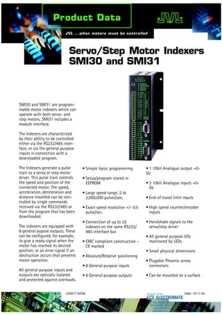
- 1. LD0017-02GB Date: 10-11-04 Servo/Step Motor Indexers SMI30 and SMI31 SMI30 and SMI31 are program- mable motor indexers which can operate with both servo- and step motors. SMI31 includes a module interface. The Indexers are characterized by their ability to be controlled either via the RS232/485 inter- face, or via the general purpose inputs in connection with a downloaded program. The Indexers generate a pulse train to a servo or step motor driver. This pulse train controls the speed and position of the connected motor. The speed, acceleration, deceleration and distance travelled can be con- trolled by single commands received via the RS232/485 or from the program that has been downloaded. The indexers are equipped with 8 general pupose outputs. These can be configured, for example, to give a ready signal when the motor has reached its desired position, or an error signal if an obstruction occurs that prevents motor operation. All general purpose inputs and outputs are optically isolated and protected against overloads. • Simple basic programming • Setup/program stored in EEPROM • Large speed range. 2 to 2,000,000 pulses/sec. • Exact speed resolution +/- 0.5 pulse/sec. • Connection of up to 32 indexers on the same RS232/ 485 interface bus • EMC compliant construction - CE marked • Absolute/Relative positioning • 8 General purpose inputs • 8 General purpose outputs • 1 10bit Analogue output +0- 5V • 2 10bit Analogue inputs +0- 5V • End-of travel limit inputs • High speed counter/encoder inputs • Handshake signals to the servo/step driver • All general purpose I/Os monitored by LEDs • Small physical dimensions • Plugable Phoenix screw connectors • Can be mounted on a surface ELECTROMATE Toll Free Phone (877) SERVO98 Toll Free Fax (877) SERV099 www.electromate.com sales@electromate.com Sold & Serviced By:
- 2. JVL Industri Elektronik A/S Blokken 42 DK-3460 Birkerød, Denmark Tel: +45 4582 4440 Fax: +45 4582 5550 E-mail: jvl@jvl.dk www.jvl.dk TT2026GB SUB-D 9-pole Female Interface connector. Connected to PC or terminal for set-up/programming of Indexer Indicates Indexer is switched on Indicates program is running Indicates motor is running Indicates an error has occurred The 8 user inputs are available at this connector. Additionally, the end-of-travel limit inputs and the Home input are available at this connector. The status of each input is displayed at the corresponding LED. The 8 user outputs are available at this connector. The status of each output is displayed at the corresponding LED. Additionallythe LED "OE" indicates if one of the outputs has been short-circuited. This connector includes power input, 2 analogue inputs and 1 analogue output. For the SMI31, the JVL-bus interface is also available. Mounting plate.The indexer can be mounted on a surface, in a cabinet, etc. O1 B A AO AI2 AI1 P P + I I1 I2 I3 I4 I5 I6 I7 I8 I NL PL HM ERROR MOTOR PROGRAM POWER O+ OE O2 O3 O4 O5 O6 O7 O8 SUB-D 9-pole Male Driver connector. Connected to servo or step motor driver. Pulse, direction and other relevant signals are available at this connector. DRIVER RS232 RS485 SMI30 and SMI31 - Servo/Step Motor Indexers Connections Physical Dimensions 43 100 160 O1 B A AO1 AI2 AI1 P- P+ I- I1 I2 I3 I4 I- I5 I6 I7 I8 I- NL PL HM ERROR MOTOR PROGRAM POWER O+ OE DRIVER RS232 O2 O3 O4 O5 O6 O7 O8 O- 144 80 16 50 55 TT2027GB ∅=4.2 ∅=5 ∅=4.2 4 All measurements in mm ±0.2mm System Configuration Technical Data The figure below illustrates typical options for building up a servo or step motor system using the SMI Indexers. The PC or PLC is only necessary for programming or monitoring. Thereafter the Indexer normally controls program execution, possibly in conjunction with a PLC as an overall controller in applications where many different units are controlled interdependently. Fieldbus connection with Field Bus Gateway FBG10 Start, Stop, Error TT2028GB PC MotoWare with JVL software, for programming the controller PLC Keyboard/Display Module KDM10 (for keying-in and displaying data) Input/Output Module IOM11 (For extending the number of inputs and outputs) Multicounter Modul CMO10 (For counting and regulating using impulses from signal sources) RS485 Interface connection (2-core twisted pair),(SMI31 only) Analogue in Driver Pulse and direction Encoder signal Servo or Step motorPotentiometer for selection of velocity, length etc. Servo/Step Motor Indexer SMI30 or SMI31 Inductive sensors, e.g. for mechanical zero-point and end stops A0 1 0 A1 A2 A3 A4 A5 A6 VALID Power+24V GND RS232 Busy Field Bus Ready RS232 FieldBus Error Adress O1 B A AO AI2 AI1 P P + I I1 I2 I3 I4 I5 I6 I7 I8 I NL PL HM ERROR MOTOR PROGRAM POWER O+ OE O2 O3 O4 O5 O6 O7 O8 DRIVER RS232 RS485 Description Min. Typ. Max. Units Supply Supply Voltage 10 45 VDC Power consumption 3 W Driver Connector Output level (CLK;DIR) 0 5 V Pulse frequency 0 2 MHz User Inputs Input Impedance 1.5 kOhm Logic ”0” -1 2.5 VDC Logic ”1” 4.5 30 VDC User Outputs Supply Voltage 6 28 VDC Loaded Current 250 mA Analogue Input Input Voltage (nom.) 0 5 VDC Input Impedance 10 kOhm Various Operating Temp. 0 45 °C Weight 500 g Example of program: WAIT IN1 = 1 ;Wait for Input1 OUT1 = 1 ;Activate Output1 SR = 10 000 ;Run motor 10 000 pulses WAIT RS = 0 ;Wait for motor stopped OUT1 = 0 ;Clear Output1 D = 100 ;Pause 1 sec. J0 ;Jump to beginning of program ELECTROMATE Toll Free Phone (877) SERVO98 Toll Free Fax (877) SERV099 www.electromate.com sales@electromate.com Sold & Serviced By: