Iai rcs2 sa6_r_specsheet
•
0 gefällt mir•132 views

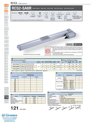
The document provides specifications for the RCS2-SA6R ROBO Cylinder actuator. It includes details on its configuration name breakdown, specifications such as load capacity and speed by stroke, dimensions and weights by stroke, compatible controller options, and cable length options. The actuator is a slider type with a 58mm width and uses a 200V servo motor that can be side mounted on either the left or right.

Empfohlen
Weitere ähnliche Inhalte
Was ist angesagt?
Was ist angesagt? (20)
Ähnlich wie Iai rcs2 sa6_r_specsheet
Ähnlich wie Iai rcs2 sa6_r_specsheet (14)
Mehr von Electromate
Mehr von Electromate (20)
Kürzlich hochgeladen
Kürzlich hochgeladen (20)
Iai rcs2 sa6_r_specsheet
- 1. RCS2 ROBO Cylinder RCS2-SA6R ROBO Cylinder Slider Type 58mm Width 200V Servo Motor Side Mounted Motor * See page Pre-35 for explanation of each code that makes up the configuration name. Actuator Specifications O I N ■ Lead and Load Capacity ■ Stroke and Maximum Speed Max. Load Capacity Rated Model Stroke Legend 1 Encoder 2 Stroke 3 Compatible controller 4 Cable length 5 Options Encoder & Stroke List 4 Cable List Type Cable Symbol Standard Price Standard Special Lengths Robot Cable P (1m) S (3m) M (5m) X06 (6m) ~ X10 (10m) X11 (11m) ~ X15 (15m) X16 (16m) ~ X20 (20m) R01 (1m) ~ R03 (3m) R04 (4m) ~ R05 (5m) R06 (6m) ~ R10 (10m) R11 (11m) ~ R15 (15m) R16 (16m) ~ R20 (20m) — — — — — — — — — — — * For cables for maintenance, see page A-39. Item Description Drive System Positioning Repeatability Lost Motion Base Allowable Static Moment Allowable Dynamic Moment (*) Overhang Load Length Ambient Operating Temp./Humidity Directions of Allowable Load Moments Overhang Load Length L L Ma Mb Mc Ma Mc 5 Option List Actuator Specifications – – – – – – – – – – – – — — — — — — — — — — — — 50 100 150 200 250 300 350 400 450 500 550 600 (1) When the stroke increases, the maximum speed will drop to prevent the ball screw from reaching the critical rotational speed. Use the actuator specification table below to check the maximum speed at the stroke you desire. (2) The load capacity is based on operation at an acceleration of 0.3G (0.2G for the 3mm-lead model). These values are the upper limits for the acceleration. (Unit: mm/s) Stroke Lead 50 ~ 450 (50mm increments) 550 (mm) 640 320 160 500 (mm) 760 380 190 800 400 200 600 (mm) 540 270 135 12 6 3 Motor Output (W) Lead (mm) Horizontal (kg) Vertical (kg) Thrust (N) (mm) RCS2-SA6R- 1 -30-12- 2 - 3 - 4 - 5 RCS2-SA6R- 1 -30-6- 2 - 3 - 4 - 5 RCS2-SA6R- 1 -30-3- 2 - 3 - 4 - 5 30 12 6 3 6 12 18 1.5 3 6 24.2 48.4 96.8 50 ~ 600 (50mm increments) Standard Price 1 Encoder Type Name Option Code See Page Standard Price B HS NM ML MR SR Brake Home sensor Reversed-home Left-Mounted Motor (Standard) Right-Mounted Motor Slider Roller — — — — — — Technical References P. A-5 Pictured: Left-mounted motor model (ML). → A-25 → A-32 → A-33 → A-33 → A-33 → A-36 Ball screw Ø10mm C10 grade ±0.02mm 0.1mm or less Material: Aluminum (white alumite treated) Ma: 38.3N∙m Mb: 54.7N∙m Mc: 81.0N∙m Ma: 8.9 N∙m Mb: 12.7 N∙m Mc: 18.6 N∙m Ma direction: 220mm or less Mb∙Mc direction: 220mm or less 0~40°C, 85% RH or less (Non-condensing) (*) Based on 5,000km travel life. Incremental Absolute I A 2 Stroke (mm) 30: 30W Servo motor I : Incremental A : Absolute T1: XSEL-J/K T2: SCON SSEL XSEL-P/Q N : None P : 1m S : 3m M : 5m X □□ : Custom Length R □□ : Robot Cable See Options below * Be sure to specify which side the motor is to be mounted (ML/MR). 50: 50mm 〜 600:600mm (50mm pitch increments) 12 : 12mm 6 : 6mm 3 : 3mm ■ Configuration: RCS2 SA6R 30 Series Type Encoder Motor Lead Stroke Compatible Controllers Cable Length Option 121 RCS2-SA6R Slider Type Mini Standard Controllers Integrated Rod Type Mini Standard Controllers Integrated Table/Arm /Flat Type Mini Standard Gripper/ Rotary Type Linear Servo Type Cleanroom Type Splash-Proof Controllers PMEC /AMEC PSEP /ASEP ROBO NET ERC2 PCON ACON SCON PSEL ASEL SSEL XSEL Pulse Motor Servo Motor (24V) Servo Motor (200V) Linear Servo Motor P T Notes on Selection Sold & Serviced By: ELECTROMATE Toll Free Phone (877) SERVO98 Toll Free Fax (877) SERV099 www.electromate.com sales@electromate.com
- 2. RCS2 ROBO Cylinder CAD drawings can be downloaded from IAI website. www.intelligentactuator.com For Special Orders P. A-9 Slider height: 53 +0.012 4 2-ø5H7 depth 6 4-M5 depth 9 50 Cable joint connector *1 (Reamer hole tolerance ±0.02) P (pitch for ø4 hole and oblong hole) Ma moment offset reference position *3 ■ Dimensions/Weight by Stroke * Brake-equipped models are heavier by 0.3kg. 3 Compatible Controllers The RCS2 series actuators can operate with the controllers below. Select the controller according to your usage. Name External View Description Max. Positioning Points Input Voltage Power Model Supply Capacity Standard Price See Page Positioner Mode Pulse Train Input Control Type Program Control 1-6 Axis Type SCON-C-30D1-NP-2-2 → P547 SSEL-C-1-30D1-NP-2-2 XSEL-3-1-30D1-N1-EEE-2-4 Solenoid Valve Mode Positioning is possible for up to 512 points 512 points Single-Phase AC 100V Single-Phase AC 200V 3-Phase AC 200V (XSEL-P/Q only) 360VA max. * When operating a 150W single-axis model Operable with same controls as solenoid valve. 7 points Dedicated to serial communication 64 points Dedicated to Pulse Train Input (−) Programmed operation is possible Can operate up to 2 axes Programmed operation is possible Can operate up to 6 axes 20000 points 20000 points → P577 → P587 — — — Serial Communication Type Program Control 1-2 Axis Type * For SSEL and XSEL, only applicable to the single-axis model. * 1 is a placeholder for the encoder type (I: incremental, A: absolute). * 2 is a placeholder for the power supply voltage (1: 100V, 2: single-phase 200V, 3: 3-phase 200V). * 3 is a placeholder for the XSEL type name (J, K, P, or Q). * 4 is a placeholder for the power supply voltage (1: 100V, 2: single-phase 200V, 3: 3-phase 200V). For adjusting position For adjusting position ø8 hole slot L 23.7 3 st 18.7 34 3 115 Reference surface 5 (58) (56) 5 0 ME SE Home ME *2 Secure at least 100 107 (146 if brake-equipped) 23 31 60 50 32±0.02 21 123 Details of the slot area for adjusting Details of section A slider position (Actuator's reference side) Details of oblong hole 123 Actuator width: 58 58 7 56 39 23 52 A 28 43 Bottom of base 1 40 N (ø4 hole pitch) 100 (ø4 hole pitch) m-M5 depth 8 31 Oblong hole depth 5 from bottom of base 3-ø4H7 depth 5 from bottom of base Base end-face Base end-face 10.2 8 R U×100 P 8 Dimensions Stroke 50 100 150 200 250 300 350 400 450 500 550 600 L N P R U m Weight (kg) 241.4 81 66 81 1 6 1.7 341.4 181 166 81 2 8 2.1 441.4 281 266 81 3 10 2.5 541.4 381 366 81 4 12 2.9 641.4 481 466 81 5 14 3.3 741.4 581 566 81 6 16 3.7 291.4 131 116 31 2 8 1.9 391.4 231 216 31 3 10 2.3 491.4 331 316 31 4 12 2.7 591.4 431 416 31 5 14 3.1 691.4 531 516 31 6 16 3.5 791.4 631 616 31 7 18 3.9 *1 The motor-encoder cable is connected here. See page A-39 for details on cables. *2 When homing, the slider moves to the ME; therefore, please watch for any interference with the surrounding objects. ME: Mechanical end SE: Stroke end *3 Reference position for calculating the moment Ma. RCS2-SA6R 122 Slider Type Mini Standard Controllers Integrated Rod Type Mini Standard Controllers Integrated Table/Arm /Flat Type Mini Standard Gripper/ Rotary Type Linear Servo Type Cleanroom Type Splash-Proof Controllers PMEC /AMEC PSEP /ASEP ROBO NET ERC2 PCON ACON SCON PSEL ASEL SSEL XSEL Pulse Motor Servo Motor (24V) Servo Motor (200V) Linear Servo Motor Sold & Serviced By: ELECTROMATE Toll Free Phone (877) SERVO98 Toll Free Fax (877) SERV099 www.electromate.com sales@electromate.com