[2024]Digital Global Overview Report 2024 Meltwater.pdf
Harmonic fb specshseet
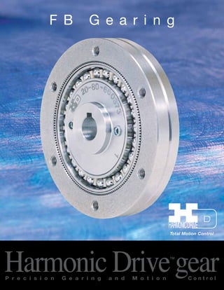
1. F B G e a r i n g
Total Motion Control Harmonic Drive™gear P r e c i s i o n G e a r i n g a n d M o t i o n C o n t r o l
2. 2
The Basic Component Set
{ { {
1) The Wave generator (WG) is a thin raced bearings
assembly fitted onto an elliptical plug, and normally
is the rotating input member.
2) The Flexspline (FS) is a non-rigid ring with external
teeth on a slightly smaller pitch diameter than the
Circular Spline. It is fitted over and is elastically
deflected by the Wave Generator.
3) The Circular Spline (CS) is a rigid ring with internal
teeth, engaging the teeth of the Flexspline across
the major axis of the Wave Generator.
4) The Dynamic Spline (DS) is a rigid ring having
internal teeth of same number as the Flexspline. It
rotates together with the Flexspline and serves as
the output member. It is identified by chamfered
corners at its outside diameter.
Contents
Compact, High Ratio, In-Line Gearing................................ 2
The Basic Component Set.................................................. 2
Configuration....................................................................... 3
Typical Installation............................................................... 3
Ordering Information........................................................... 3
Dimensions.......................................................................... 4
Performance Ratings........................................................... 5
Lubrication........................................................................... 6
Installation........................................................................... 6
Efficiency............................................................................. 7
No-Load Running Torque, Starting Torque,
and Back Driving Torque..................................................... 7
Compact, High Ratio, In-Line Gearing
Harmonic Drive™ FB “Pancake” type component set offers the designer high ratio, in-line mechanical power
transmissions in extremely compact configurations. The component set consists of four elements: the Wave
generator, an elliptical bearing assembly; the Flexspline, a non-rigid ring with external teeth; and the Circular
Spline and the Dynamic Spline, rigid internal gears.
Rotation of the Wave Generator imparts a rotating elliptical shape to the Flexspline causing progressive
engagement of its external teeth with the internal teeth of the Circular Spline and the Dynamic Spline.
The fixed Circular Spline has two more teeth than the Flexspline, thereby imparting relative rotation to the
Flexspline at a reduction ratio corresponding to the difference in the number of teeth. With the same number
of teeth, the Dynamic Spline rotates with and at the same speed as the Flexspline.
Sold & Serviced By:
ELECTROMATE
Toll Free Phone (877) SERVO98
Toll Free Fax (877) SERV099
www.electromate.com
sales@electromate.com
3. Typical Installation
FB “pancake” type component sets are easier to use than conventional gearing. All that is required is suitable
bearing support for the input and output shaft, and a means of fixing the circular spline against rotation.
The simplicity of FB component sets is demonstrated in the typical arrangements shown below.
3
Configurations
1) Reduction Gearing
WG Input
CS Fixed
DS Output
Ratio as listed
Input and output in opposite
direction.
2) Reduction Gearing
WG Input
CS Output
DS Fixed
Ratio
1
R+1
Input and output in same direction.
Output
Input
Output
Input
Output Input
4) Differential
WG Control Input
CS Main-drive Input
DS Main-drive Output
Numerous differential functions can
be obtained by combinations of
speeds and rotations on the three
shafts.
3) Reduction Gearing
WG Fixed
CS Output
DS Input
Ratio
R
R+1
Input and output in same direction.
Output Input
1. Wave Generator
2. Flexspline
3. Circular Spline
4. Dynamic Spline
5. Motor
6. Input Shaft or Motor Shaft
7. Output Shaft
Ordering Information
Pancake model with the single row bearing Wave Generator
Size 20
Reduction ratio 80:1
Component set
Backlash optimized to below 3 arc minutes (Optional)
Suffix indicating that the set is specially modified or designed
according to customer requirements.
FB 20-80-2G-R-SP
Sold & Serviced By:
ELECTROMATE
Toll Free Phone (877) SERVO98
Toll Free Fax (877) SERV099
www.electromate.com
sales@electromate.com
4. -0.034 5 0.5 10.5 15.0 3.75 0.75 44 M3 6 +0.012
-0.040 6 0.5 12.5 11.4 0.95 2.05 60 M4 9 +0.015
-0.047 8 0.5 16.5 12.8 0.35 3.35 75 M5 14 +0.018
-0.047 10 0.5 20.5 15.6 0.95 3.95 100 M6 14 +0.018
-0.054 13 1 27.0 19.4 1.80 5.80 120 M8 14 +0.018
-0.054 16 1 33.0 23.2 2.90 6.90 150 M10 19 +0.021
4
Dimensions
FB A
(g7) B C D E F1 F2 G H
I J
(JS9) K L M N X Y
Wt
(H7) Max lb kgf
14 50 -0 . 00 9
0 8 — — 29 14 — 0.2 1.0 0.2 0.1
20 70 -0 . 01 0
0 12 3±0.0125 10.4 42 20 — 0.2 1.0 0.2 1.0
25 85 -0 . 01 2
0 15 5±0.0150 16.3 53 26 0.9 0.2 1.5 1.1 0.5
32 110 -0 . 01 2
0 15 5±0.0150 16.3 69 26 0.8 0.2 1.5 2.2 1.0
40 135 -0 . 01 4
0 20 5±0.0150 16.3 84 32 1.2 0.4 2.0 4.0 1.8
50 170 -0 .0 1 4
0 20 6±0.0150 21.8 105 32 1.1 0.4 2.0 6.4 2.9
Maximum housing I.D. for Flexspline axial containment is L. The surface hardness in the region where the
Flexspline abuts the housing is recommended to be HRC 29–34.
Sold & Serviced By:
ELECTROMATE
Toll Free Phone (877) SERVO98
Toll Free Fax (877) SERV099
www.electromate.com
sales@electromate.com
6. 6
Lubrication
Oil lubrication ratings are based on Molub Alloy gear
Oil No. 80. See table for recommended oil level and
volume for horizontal shaft mounting.
For vertical mounting the recommended level is at the
wave generator bearing ball centerline or midpoint of
the drive.
Grease lubricated ratings are based on Harmonic
Grease HC-1, which has been specially developed
for Harmonic Drive™ FB product. Alternate lubricants
include Molub Alloy Grease No. 2, Shell Alvania EP 1
and their equivalents.
For retention of grease within the tooth mesh area
and the ball bearing, it is recommended that the L
dimension (see FB Dimensions, page 4) be extended
further inward to at least S.
FB 14 20 25 32 40 50
Oil Level Below Drive Centerline mm 7.6 12.7 15.2 17.8 23.0 30.5
FB 14 20 25 32 40 50
S 26 38 48 63 76 95
mm
Installation
The Dynamic Spline is distinguished by its chamfered outer edge. FB Component Sets may be operated in
any attitude. Recommended installed relationships are shown below:
Housing Tolerance
FB a b c d e f g h
14 0.013 0.015 0.016 0.013 0.015 0.016 0.011 0.007
20 0.017 0.016 0.020 0.017 0.016 0.020 0.013 0.010
25 0.024 0.016 0.029 0.024 0.016 0.029 0.016 0.012
32 0.026 0.017 0.031 0.026 0.017 0.031 0.016 0.012
40 0.026 0.019 0.031 0.026 0.019 0.031 0.017 0.012
50 0.028 0.024 0.034 0.028 0.024 0.034 0.021 0.015
mm
Sold & Serviced By:
ELECTROMATE
Toll Free Phone (877) SERVO98
Toll Free Fax (877) SERV099
www.electromate.com
sales@electromate.com
7. 7
Efficiency
Efficiency varies depending on input speed, ratio, load level, temperature, and type of lubrication. The effects
of these factors are illustrated in the curves shown below.
FB Efficiency vs. Ratio, Temperature, and Lubricant (At Rated Torque)
Input Speed 500 rpm
Input Speed 1700 rpm
Input Speed 3400 rpm
No-Load Running Torque, Starting Torque, and Backdriving Torque
FB 14 20 25 32 40 50
NL Running Torque
@ 1500 rpm
Ncm 3~8 5~11 6~30 15~40 20~65 60~150
oz-in 4~11 7~15 8~42 20~56 28~90 83~210
Starting Torque
Ncm 0.5~3 0.8~4 2~7 3~10 5~30 10~60
oz-in 0.7~4 1~6 3~10 4~14 7~42 14~83
Backdriving Torque
Nm 0.8~7 2~10 3~38 4~40 8~60 20~110
lb-in 6~60 17~87 26~330 35~350 70~520 170~950
Values quoted are based on actual tests with the component sets assembled in housings, and takes into
coEnLsiEdeCrTatRioOn MfriActTioEn resistance of oils seals, and churning of oil.
Sold & Serviced By:
Toll Free Phone (877) SERVO98
Toll Free Fax (877) SERV099
www.electromate.com
sales@electromate.com