1. ACCELERA
Features
■ Packaged controller in 1 through 8 axis versions:
DMC-40x0 where x=1,2,3,4,5,6,7,8 axes
■ (1) 10/100BASE-T Ethernet port with Auto MDIX
(2) RS232 ports up to 115 kbaud
■ User-configurable for stepper or servo motors on any
combination of axes. Optional firmware for piezo-ceramic
motors. Configurable for sinusoidal commutation
■ Accepts up to 22 MHz encoder frequencies for servos.
Outputs pulses up to 6 MHz for steppers
■ PID compensation with velocity and acceleration feedfor-ward,
integration limits, notch filter and low-pass filter
■ Modes of motion include jogging, point-to-point position-ing,
contouring, PVT, linear and circular interpolation,
electronic gearing and electronic cam. Features elliptical
scaling, slow-down around corners, infinite segment feed
and feedrate override
■ Over 200 English-like commands including conditional
statements and event triggers
■ Non-volatile memory for programs, variables and arrays.
Multitasking for concurrent execution of up to eight
programs
■ Optically isolated home input and forward and reverse
end-of-travel limits for every axis.
■ Uncommitted, isolated inputs and isolated outputs
1- through 4-axis models: 8 inputs and 8 outputs
5- through 8-axis models: 16 inputs and 16 outputs
■ Isolated, high-power outputs for driving brakes or relays
■ High speed position latch for each axis and output compare
■ 8 uncommitted analog inputs
■ 32 additional 3.3 V I/O (5 V option)
■ 2 line x 8 character programmable LCD
■ Dual encoder inputs for each servo axis
■ Accepts single 20–80 VDC input
■ Available with internal stepper and servo drives.
Or, connect to external drives of any power range
■ Communication drivers for Windows, Mac OSX, and Linux
■ Custom hardware and firmware options available
■ DMC-40x0 has CE certification. Specify DMC-40x0-ETL
for ETL certification
Product Description
The DMC-40x0 is Galil’s highest performance, stand-alone
motor controller. It belongs to Galil’s latest gen-eration
motion controller family: the Accelera Series,
which accepts encoder inputs up to 22 MHz, provides
servo update rates as high as 32 kHz, and processes
commands in as fast as 40 microseconds—10 times
faster than prior generation controllers.
The DMC-40x0 is a full-featured motion controller
packaged with optional
multi-axis drives in a com-pact,
metal enclosure. The
unit operates stand-alone
or interfaces to a PC with
Ethernet 10/100Base-T
or RS232. The controller
includes optically isolated
I/O, high-power outputs
capable of driving brakes
or relays, and analog inputs for interfacing to analog
sensors. The DMC-40x0 controller and drive unit accepts
power from a single 20–80 VDC source.
The DMC-40x0 is available in one through eight
axis formats, and each axis is user-configurable for
stepper or servo motor operation. Standard program-ming
features include PID compensation with velocity
and acceleration feedforward, multitasking for simul-taneously
running up to eight programs, and I/O pro-cessing
for synchronizing motion with external events.
Modes of motion include point-to-point positioning,
position tracking, jogging, linear and circular interpola-tion,
PVT, contouring, electronic gearing and electronic
cam (ECAM). Like all Galil controllers, the DMC-40x0
controllers use Galil’s popular, intuitive command lan-guage,
making them very easy to program. GalilTools
servo design software further simplifies system set-up
with “one-button” servo tuning and real-time display
of position and velocity information.
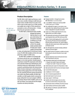
DMC-4040 4-axis
and DMC-4080 8-axis
controllers
Ethernet/RS232 Accelera Series, 1–8 axes
DMC-40x0 Series
Sold & Serviced By:
ELECTROMATE
Toll Free Phone (877) SERVO98
Toll Free Fax (877) SERV099
www.electromate.com
sales@electromate.com
2. Ethernet/RS232 Accelera Series, 1–8 axes
DMC-40x0 Series
Specifications
System Processor
■ RISC-based, clock multiplying processor with DSP functions
Communications Interface
■ (1) 10/100BASE-T Ethernet port with Auto MDIX
■ (2) RS232 ports up to 115 kbaud
Commands are sent in ASCII. A binary communication mode is also
available as a standard feature
Modes of Motion:
■ Point-to-point positioning
■ Position Tracking
■ Jogging
■ 2D Linear and Circular Interpolation with feedrate override
■ Linear Interpolation for up to 8 axes
■ Tangential Following
■ Helical
■ Electronic Gearing with multiple masters and ramp-to-gearing
■ Gantry Mode
■ Electronic Cam
■ Contouring
■ PVT (Position-Velocity-Time)
■ Teach and playback
Memory
■ Program memory size—2000 lines × 80 characters
■ 510 variables
■ 16,000 total array elements in up to 30 arrays
Filter
■ PID with velocity and acceleration feedforward
■ Notch filter and low-pass filter
■ Dual-loop control for backlash compensation
■ Velocity smoothing to minimize jerk
■ Integration limit
■ Torque limit
■ Offset adjustment
Kinematic Ranges
■ Position: 32 bit (±2.15 billion counts per move; automatic rollover;
no limit in jog or vector modes)
■ Velocity: Up to 22 million counts/sec for servo motors
■ Acceleration: Up to 1 billion counts/sec2
Uncommitted I/O
ISOLATED ISOLATED ANALOG 3.3 V
INPUTS OUTPUTS INPUTS I/O
DMC-4010 thru -4040 8 8 8 32
DMC-4050 thru -4080 16 16 8 32
Sold & Serviced By:
High Speed Position Latch
■ Uncommitted inputs 1-4 latch A,B,C,D and 9-12 latch E, F, G, H axes
(latches within 40 microseconds with optoisolation)
Dedicated Inputs (per axis)
■ Main encoder inputs—Channel A, A-, B,B-,I, I- (±12 V or TTL)
■ Dual encoder (for axes configured as servo)—Channel A, A-, B, B-
■ Forward and reverse limit inputs—optoisolated
■ Home input—optoisolated
■ Selectable high-speed position latch input—optoisolated
■ Selectable abort input for each axis—optoisolated
Dedicated Outputs (per axis)
■ Analog motor command output with 16-bit DAC resolution
■ Pulse and direction output for step motors
■ PWM output also available for servo amplifiers
■ Amplifier enable output
■ Error output (one per controller)
■ High-speed position compare output (per set of 4 axes)
Minimum Servo Loop Update Time
STANDARD -FAST*
■ 1–2 axes: 62 μsec 31 μsec
■ 3–4 axes: 125 μsec 62 μsec
■ 5–6 axes: 156 μsec 94 μsec
■ 7–8 axes: 187 μsec 125 μsec
Maximum Encoder Feedback Rate
■ 22 MHz
Maximum Stepper Rate
■ 6 MHz (Full, half or microstep)
Power Requirements
■ 20–80 VDC
Environmental
■ Operating temperature: 0–70º C
■ Humidity: 20–95% RH, non-condensing
Mechanical
■ 1- thru 4-axis: 8.1" × 7.25" × 1.72"
5- thru 8-axis: 11.5" × 7.25" × 1.72"
Connectors
■ Amplifier I/O: 44-pin HD Male D-sub
■ General I/O: 44-pin HD Female D-sub
■ Encoder: 15-pin HD Female D-sub
■ Analog: 15-pin LD Male D-sub
■ Extended I/O: 44-pin HD Male D-sub
*Reduced feature set for -FAST.
ACCELERA
ELECTROMATE
Toll Free Phone (877) SERVO98
Toll Free Fax (877) SERV099
www.electromate.com
sales@electromate.com
3. Ethernet/RS232 Accelera Series, 1–8 axes
Instruction Set
Ethernet
DH DHCP Configuration
HS Handle switch
IA Set IP address
IH Open IP handle
IK Ethernet port blocking
MB Modbus
MW Modbus wait
SA Send command
SM Subnet mask
Servo Motor
AF Analog feedback
AG Set amplifier gain
AU Set current loop gain
AW Report AMP-43040 bandwidth
DV Dual loop operation
FA Acceleration feedforward
FV Velocity feedforward
IL Integrator limit
KD Derivative constant
KI Integrator constant
KP Proportional constant
NB Notch bandwidth
NF Notch frequency
NZ Notch zero
OF Offset
PL Pole
SH Servo here
TK Peak torque
TL Torque limit
TM Sample time
Stepper Motor
KS Stepper motor smoothing
LC Low current
QS Error magnitude
YA Step drive resolution
YB Step motor resolution
YC Encoder resolution
YR Error correction
YS Stepper position maintenance
Internal Sine Commutation
BA Brushless axis
BB Brushless phase
BC Brushless calibration
BD Brushless degrees
BI Brushless inputs
BM Brushless modulo
BO Brushless offset
BS Brushless setup
BX Sine Amp Initialization
BZ Brushless zero
I/O
AL Arm latch
AQ Analog configuration
CB Clear bit
CO Configure I/O points
II Input interrupt
OB Define output bit
OC Output compare function
OP Output port
SB Set bit
@AN[x] Value of analog input x
@IN[x] State of digital input x
@OUT[x] State of digital output x
System Configuration
BN Burn parameters
BP Burn program
BR Brush motor enable
BV Burn variables and arrays
BW Brake Wait
CC Configure communications port
CE Configure encoder type
CF Configure unsolicited messages handle
CI Configure communication interrupt
CN Configure switches
CW Data adjustment bit
DE Define dual encoder position
DP Define position
DR Data record update rate
EI Event interrupts
EO Echo
IT Independent smoothing
LB LCD Bias contrast
ˆLˆK Program protect (Lock)
LU LCD Update
LZ Leading zeros format
MO Motor off
MT Motor type
PF Position format
PW Password
QD Download array
RS Reset
ˆRˆS Master reset
UI User interrupt
VF Variable format
Math Functions
@ABS[x] Absolute value of x
@ACOS[x] Arc cosine of x
@ASIN[x] Arc sine of x
@ATAN[x] Arc tangent of x
@COM[x] 1’s complement of x
@COS[x] Cosine of x
@FRAC[x] Fraction portion of x
@INT[x] Integer portion of x
@RND[x] Round of x
@SIN[x] Sine of x
@SQR[x] Square root of x
@TAN[x] Tangent
% Modulus operator
Interrogation
ID AMP ID
LA List arrays
LL List labels
LS List program
LV List variables
MG Message command
QH Query hall state
QR Data record
QU Upload array
QZ Return data record information
RL Report latch
RP Report command position
ˆRˆV Firmware revision information
SC Stop code
TA Tell amplifier status
TB Tell status
TC Tell error code
Interrogation (cont.)
TD Tell dual encoder
TE Tell error
TH Tell handle
TI Tell input
TP Tell position
TR Trace program
TS Tell switches
TT Tell torque
TV Tell velocity
TZ Tell I/O configuration
WH Which handle
Programming
BK Breakpoint
DA Deallocate variables/arrays
DL Download program
DM Dimension arrays
ED Edit program
ELSE Conditional statement
ENDIF End of cond. statement
EN End program
HX Halt execution
IF If statement
IN Input variable
JP Jump
JS Jump to subroutine
NO No-operation—for comments
RA Record array
RC Record interval
RD Record data
RE Return from error routine
REM Remark program
RI Return from interrupt routine
SL Single step
UL Upload program
XQ Execute program
ZA Data record variables
ZS Zero stack
‘ Comment
Error Control
BL Backward software limit
ER Error limit
FL Forward software limit
LD Limit disable
OA Encoder failure
OE Off-on-error function
OT Encoder failure period
OV Encoder failure voltage
TW Timeout for in-position
Trippoint
AD After distance
AI After input
AM After motion profiler
AP After absolute position
AR After relative distance
AS At speed
AT After time
AV After vector distance
MC Motion complete
MF After motion—forward
MR After motion—reverse
WT Wait for time
Sold & Serviced By:
ELECTROMATE
Toll Free Phone (877) SERVO98
Toll Free Fax (877) SERV099
Independent Motion
AB Abort motion
AC Acceleration
BG Begin motion
DC Deceleration
FE Find edge
FI Find index
HM Home
HV Home speed
IP Increment position
IT Smoothing time constant
JG Jog mode
PA Position absolute
PR Position relative
PT Position tracking
SD Switch deceleration
SP Speed
ST Stop
Contour Mode
CD Contour data
CM Contour mode
DT Contour time interval
PVT Mode
BT Coordinate start
PV Position, velocity, time
ECAM/Gearing
EA ECAM master
EB Enable ECAM
EC ECAM table index
EG ECAM go
EM ECAM modulus
EP ECAM interval
EQ Disengage ECAM
ET ECAM table entry
EW ECAM widen
EY ECAM cycle counter
GA Master axis for gearing
GD Engagement distance for gearing
GM Gantry mode
_GP Correction for gearing
GR Gear ratio for gearing
Vector/Linear Interpolation
CA Define vector plane
CR Circular interpolation move
CS Clear motion sequence
ES Elliptical scaling
IT Smoothing time constant
LE Linear interpolation end
LI Linear interpolation segment
LM Linear interpolation mode
ST Stop motion
TN Tangent
VA Vector acceleration
VD Vector deceleration
VE Vector sequence end
VM Coordinated motion mode
VP Vector position
VR Vector speed ratio
VS Vector speed
VV Vector Velocity
DMC-40x0 Series
ACCELERA
www.electromate.com
sales@electromate.com
4. Ethernet/RS232 Accelera Series, 1–8 axes
DMC-40x0 Series
ACCELERA 4
Connectors—Communications
RS-232 Main Port (DCE)
9-pin; Low-density Male D-sub
1 NC
2 Transmit data-output (TxD)
3 Receive data-input (RxD)
4 NC
5 Ground
6 NC
7 Clear to send-input (CTS)
8 Request to send-output (RTS)
9 NC
RS232 Auxiliary Port (DTE)
9-pin; Low-density Female D-sub
1 NC
2 Receive data-input (RxD)
3 Transmit data-out put (TxD)
4 NC
5 Ground
6 NC
7 Request to send-output (RTS)
8 Clear to send-input (CTS)
9 NC/5 V (jumper select)
Ethernet 10/100Base-T
RJ-45 connector
Connectors—
Amplifier Board
AMP-43040
J2 Power**
6-pin
1 Ground
2 Ground
3 Ground
4 +VM (20 V–80 V)
5 +VM (20 V–80 V)
6 +VM (20 V–80 V)
JA1, JB1, JC1, JD1
Motor Output
4-pin
1 Motor Phase C
2 Motor Phase B
3 NC
4 Motor Phase A
Extended I/O
(ICM-42000 & -42200)
44-pin Hi-density Male D-sub
1 I/O18
2 I/O21
3 I/O24
4 I/O26
5 I/O29
6 I/O32
7 I/O33
8 I/O36
9 I/O38
10 NC
11 I/O41
12 I/O44
13 I/O47
14 NC
15 Reserved
16 I/O17
17 I/O20
18 I/O23
19 I/O25
20 I/O28
21 I/O31
22 NC
23 I/O35
24 I/O37
25 NC
26 I/O40
27 I/O43
28 I/O46
29 I/O48
30 3.3 V
31 I/O19
32 I/O22
33 Ground
34 I/O27
35 I/O30
36 Ground
37 I/O34
38 NC
39 Ground
40 I/O39
41 I/O42
42 I/O45
43 Ground
44 NC
J2 General I/O Axes A thru D
(ICM-42000 & -42200)
44-pin Hi-density Female D-sub
1 Error output*
2 Input 1-isolated
3 Input 4-isolated
4 Input 7-isolated
5 Electronic Lockout-isolated input*
6 Limit switch common
7 Home A-isolated
8 Home B-isolated
9 Home C-isolated
10 Home D-isolated
11 Output power+
12 Output 3-isolated
13 Output 6-isolated
14 Output return-
15 +5 V
16 Reset-isolated*
17 Input common
18 Input 3-isolated
19 Input 6-isolated
20 Abort-isolated*
21 NC
22 Reverse limit A-isolated†
23 Reverse limit B-isolated†
24 Reverse limit C-isolated†
25 Reverse limit D-isolated†
26 NC
27 Output 2-isolated
28 Output 5-isolated
29 Output 8-isolated
30 +5 V
31 Ground
32 Input 2-isolated
33 Input 5-isolated
34 Input 8-isolated
35 Ground
36 Forward limit A-isolated†
37 Forward limit B-isolated†
38 Forward limit C-isolated†
39 Forward limit D-isolated†
40 Ground
41 Output 1-isolated
42 Output 4-isolated
43 Output 7-isolated
44 Output Compare A–D
**Note: Power can be input through either of the amplifier connectors to power the entire unit due to power pass-thru connectors
that connect input power to all modules. For 5- through 8-axis units with two different types of amplifiers, the lower of the
maximum voltages is the maximum rating for the unit. However, if you need different voltages, you can specify the ISAMP
and/or ISCNTL option to separate the various power inputs.
When using the AMP-43140 with a power supply lower than +/-20 Volts, a separate supply of 20–80 VDC must be input
to the 2-pin connector on the side of the DMC-40X0 or specify the 12 V option for the DMC controller.
Sold & Serviced By:
ELECTROMATE
Toll Free Phone (877) SERVO98
Toll Free Fax (877) SERV099
www.electromate.com
sales@electromate.com
J2 General I/O Axes E thru H
(ICM-42000 & -42200)
44-pin Hi-density Female D-sub
1 Error output*
2 Input 9-isolated
3 Input 12-isolated
4 Input 15-isolated
5 Electronic lockout-isolated input*
6 Limit switch common
7 Home E-isolated
8 Home F-isolated
9 Home G-isolated
10 Home H-isolated
11 Output power+
12 Output 11-isolated
13 Output 14-isolated
14 Output return-
15 +5 V
16 Reset-isolated*
17 Input common
18 Input 11-isolated
19 Input 14-isolated
20 Abort-isolated*
21 NC
22 Reverse limit E-isolated†
23 Reverse limit F-isolated†
24 Reverse limit G-isolated†
25 Reverse limit H-isolated†
26 NC
27 Output 10-isolated
28 Output 13-isolated
29 Output 16-isolated
30 +5 V
31 Ground
32 Input 10-isolated
33 Input 13-isolated
34 Input 16-isolated
35 Ground
36 Forward limit E-isolated†
37 Forward limit F-isolated†
38 Forward limit G-isolated†
39 Forward limit H-isolated†
40 Ground
41 Output 9-isolated
42 Output 12-isolated
43 Output 15-isolated
44 Output Compare E–H
*Active low
†Programmable for Active high or Active low
5. Ethernet/RS232 Accelera Series, 1–8 axes
DMC-40x0 Series
ACCELERA
Connectors—I/O
JA1, JB1, JC1, JD1
Encoder Axes A thru D
(ICM-42000)
JE1, JF1, JG1, JH1
Encoder Axes E thru H
(ICM-42000)
15-pin Hi-density Female D-sub
1 Index+
2 B+
3 A+
4 Aux B+
5 Ground
6 Index-
7 B-
8 A-
9 Aux A-
10 Hall A
11 Aux A+
12 Aux B-
13 Hall B
14 Hall C
15 +5 V
J3 Analog Inputs
(ICM-42000 & -42200)
15-pin Low-density Male D-sub
1 Analog Ground
2 Analog input 1
3 Analog input 3
4 Analog input 5
5 Analog input 7
6 Analog Ground
7 -12 V
8 +5 V
9 Analog Ground
10 Analog input 2
11 Analog input 4
12 Analog input 6
13 Analog input 8
14 NC
15 +12 V
Sold & Serviced By:
Axis Connectors Axes A thru H
(ICM-42200)
26-pin Hi-density Female D-sub
1 Reserved
2 Amp Enable
3 Direction
4 Home–isolated
5 Limit switch common
6 Aux A-
7 Index+
8 A-
9 +5 V
10 Ground
11 Amp Enable Return
12 Reserved
13 Step
14 Forward limit–isolated†
15 Aux B+
16 Index-
17 B+
18 Ground
19 Motor command
20 Amp Enable Power
21 Reserved
22 Reverse limit–isolated†
23 Aux B-
24 Aux A+
25 B-
26 A+
†Programmable for Active high
or Active low
J1 Amplifier I/O
Axes A thru D
(ICM-42000)
44-pin Hi-density Male D-sub
1 Reserved
2 PWM C/Step C
3 Reserved
4 Reserved
5 Sign C/Dir C
6 Reserved
7 Amp enable A
8 Amp enable D
9 NC
10 -12 V
11 Motor command B
12 Reserved
13 NC
14 NC
15 +5 V
16 PWM A/Step A
17 Reserved
18 PWM D/Step D
19 Sign A/Dir A
20 Reserved
21 Sign D/Dir D
22 Amp enable common-1
23 Amp enable C
24 NC
25 +12 V
26 Reserved
27 Motor command C
28 Reserved
29 NC
30 NC
31 PWM B/Step B
32 Reserved
33 Ground
34 Sign B/Dir B
35 Reserved
36 Ground
37 Amp enable B
38 Amp enable common-2
39 Ground
40 Motor command A
41 Reserved
42 Motor command D
43 Ground
44 NC
J1 Amplifier I/O
Axes E thru H
(ICM-42000)
44-pin Hi-density Male D-sub
1 Reserved
2 PWM G/Step G
3 Reserved
4 Reserved
5 Sign G/Dir G
6 Reserved
7 Amp enable E
8 Amp enable H
9 NC
10 -12 V out
11 Motor command F
12 Reserved
13 NC
14 NC
15 +5 V out
16 PWM E/Step E
17 Reserved
18 PWM H/Step H
19 Sign E/Dir E
20 Reserved
21 Sign H/Dir H
22 Amp enable common-1
23 Amp enable G
24 NC
25 +12 V out
26 Reserved
27 Motor command G
28 Reserved
29 NC
30 NC
31 PWM F/Step F
32 Reserved
33 Ground
34 Sign F/Dir F
35 Reserved
36 Ground
37 Amp enable F
38 Amp enable common-2
39 Ground
40 Motor command E
41 Reserved
42 Motor command H
43 Ground
44 NC
ELECTROMATE
Toll Free Phone (877) SERVO98
Toll Free Fax (877) SERV099
www.electromate.com
sales@electromate.com
6. ACCELERA
Ethernet/RS232 Accelera Series, 1–8 axes
DMC-40x0 Series
DMC-40x0 Interconnect Options
Sold & Serviced By:
resolution. The AFn command selects sinusoidal interpolation where n
specifies 2n interpolation counts per encoder cycle (n=5 to 12). For example,
if the encoder cycle is 40 microns, AF10 results in 210=1024 counts per
cycle, or a resolution of 39 nanometers per count. With the ICM-42100, the
sinusoidal encoder inputs replace the main digital encoder inputs.
ICM-42200 Interconnect Module (-I200)
The ICM-42200 interconnect option resides inside the DMC-40x0 enclosure
and provides a pin-out that is optimized for easy connection to external
drives. The ICM-42200 uses 26-pin HD D-sub connectors for each axis that
includes encoder, limit, home, and motor command signals.
ICM-42000 Interconnect Module (-I000)
The ICM-42000 resides inside the DMC-40x0 enclosure and breaks out
the internal CPU board connector into convenient D-sub connectors for
interface to external amplifiers and I/O devices. Eight 500 mA highside
drive outputs are available (total current not to exceed 3 A). The ICM-42000
is user- configurable for a broad range of amplifier enable options including:
High amp enable, Low amp enable, 5 V logic, 12 V logic, external voltage
supplies up to 24 V and sinking or sourcing. Two ICMs are required for
5- thru 8-axis controllers.
ICM-42100 Sinusoidal Encoder Interpolation Module (-I100)
The ICM-42100 option resides inside the DMC-40x0 enclosure and accepts
sinusoidal encoder signals instead of digital encoder signals as accepted
by the ICM-42000. The ICM-42100 provides interpolation of up to four
1-volt differential sinusoidal encoders resulting in a higher position
All DMC-40x0 are ordered with an internal interconnect module (ICM) which breaks out and buffers the controller I/O and drive signals.
1-4 axis controllers require one ICM, 5-8 axis controllers require two, and can be mixed and matched from the following options.
(Key: HD=Hi-density, LD=Low-density, F=Female, M=Male, D=D-subminiature connector)
ICM (Part Number)
Unique Purpose
Inside 40x0 Enclosure
Breaks out I/O and Drive Signals
Encoder connector
Axis Connector
Analog In connector
I/O Connector
8 500mA high-side digital outs (max 3A)
Configurable Amp Enable
hi/lo, 5 V, 12 V, and ext. V, sink, source
Accepts Quad and Pulse and Direction
encoders and inputs
Sine Encoder Interpolation
SSI and BiSS options available
ICM-42000 (-I000)
Default ICM
Yes
Yes
15-pin HD F D per axis
44-pin HD M D per 4 axes
15-pin LD M D
44-pin HD F D
Yes
Yes
Yes
No
Yes
ICM-42100 (-I100)
Sine Interpolated Encoders
Yes
Yes
15-pin HD F D per axis
44-pin HD M D per 4 axes
15-pin LD M D
44-pin HD F D
Yes
Yes
Yes
Yes
No
ICM-42200 (-I200)
More convenient for external drives
Yes
Yes
26-pin HD F D per axis
On Encoder connector, and
44-pin HD M D per 4 axes
15-pin LD M D
44-pin HD F D
Yes
Yes, no need to remove cover.
Axis-independent circuitry.
Yes
No
Yes
ELECTROMATE
Toll Free Phone (877) SERVO98
Toll Free Fax (877) SERV099
www.electromate.com
sales@electromate.com
7. Sold & Serviced By:
AMP-435x0 (-D35x0)
Brushed/Brushless servo
4 x=4, 2 x=2
PWM
Sinusoidal
600
8
15
20-80
0.4, 0.8, 1.6 A
33
-
-
0.5
Yes
Yes
Yes
Yes
Yes
Yes
Shunt option
Ethernet/RS232 Accelera Series, 1–8 axes
Drive Name (Part Number)
Motor Type
Axes
Current Drive
Commutation
Axis power (Watts)
Cont. Current (Amps)
Peak Current (Amps)
Voltage Bus (VDC)
Gains
Switching Freq (Khz)
Typical Current Loop BW (kHz)*
Drive Modes
Min. Inductance (mH)
Over Voltage
Under Voltage
Over Current
Short circuit
Over temp
ELO input
Other Notes
AMP-43140 (-D3140)
Brushed servo
4
Linear
Brushed only
20 (60 max for 4 axes)
1
1
+/- 12-30 bipolar
0.1 (0.01 available) A/V
N/A
4
Linear
0.2
No
No
Fused
Fused
Thermal Shutdown
Yes
SSR option, disconnects
power at startup
AMP-43240 (-D3240)
Brushed/Brushless servo
4
PWM
Trap w/ 120° Halls
750
10
20
20-80
0.5, 1, 2 A/V
24
4
Chopper
0.2
Yes
Yes
Yes
Yes
Yes
Yes
Shunt option
Adjustable current loop
DMC-40x0 Series
ACCELERA
DMC-40x0 Servo Drive Options
24 KHz. The drive operates in chopper mode. The amplifier offers protection
for over-voltage, under-voltage, over-current, short-circuit and over-temper-ature.
Hall sensors are required for brushless motors. A shunt regulator
option is available.
AMP-435x0 2- and 4-axis 600 W Servo Drives with Sinusoidal
Commutation (-D3520, -D3540)
The AMP-43540 contains four transconductance, PWM amplifiers for driv-ing
brushless servo motors with sinusoidal commutation. Each amplifier
drives motors operating at up to 8 Amps cont., 15 Amps peak, 20–80 VDC.
The gain settings of the amplifier are user-programmable at 0.4, 0.8 and
1.6 Amp/Volt. The switching frequency is 33 KHz. The amplifier offers pro-tection
for over-voltage, under-voltage, over-current, short-circuit and
over-temperature. Hall sensors are not required for brushless motor com-mutation.
A shunt regulator option is available. A two-axis version, the
AMP-43520, is also available.
AMP-43640 4-axis 20 W Servo Drives with Sinusoidal
Commutation (-D3640)
The AMP-43640 contains four linear, transconductance amplifiers for driving
brushless servo motors with sinusoidal commutation. The AMP-43640
requires 15–30 VDC, and the gain setting of each amplifier is 0.1 A/V at
1 A maximum current. Hall sensors are not required for brushless motor
commutation.
AMP-430x0 2- and 4-axis 500 W Servo Drives (-D3020, -D3040)
The AMP-43040 contains four transconductance, PWM amplifiers for
driving brushless/brush servo motors. Operating at up to 7 Amps cont.,
10 Amps peak, 20–80 VDC. The gain settings of the amplifier are user-pro-grammable
at 0.4, 0.7 and 1 Amp/Volt. The switching frequency is 60 kHz.
The drive for each axis is software configurable to operate in either a chop-per
or inverter mode.The chopper mode is intended for operating low
inductance motors.The amplifier offers protection for over-voltage, under-voltage,
over-current, short-circuit and over-temperature. Hall sensors are
required for brushless motors. A shunt regulator option is available. A two-axis
version, the AMP-43020 is also available.
AMP-43140 4-axis 20 W Servo Drives (-D3140)
The AMP-43140 contains four linear drives for operating small, brush-type
servo motors. The AMP-43140 requires a ± 12-30 VDC input. Output power
is 20 W per amplifier or 60 W total. The gain of each transconductance linear
amplifier is 0.1 A/V at 1 A maximum current. The typical current loop band-width
is 4 kHz. An SSR option is available which guarantees absolutely no
current during motor off.
AMP-43240 4-axis 750 W Servo Drives (-D3240)
The AMP-4324 contains four transconductance, PWM amplifiers for driving
brushless/brush servo motors servo motors. Operating at up to 10 Amps
cont., 20 Amps peak, 20–80 VDC. The gain settings of the amplifier are
user-programmable at 0.5, 1 and 2 Amp/Volt. The switching frequency is
The DMC-40x0 can be optionally equipped with a multi-axis internal servo or stepper motor drive that resides inside the DMC-40x0 enclosure.
5–8 axis versions can mix and match two of the following drives.
AMP-430x0 (-D30x0)
Brushed/Brushless servo
4 x=4, 2 x=2
PWM
Trap w/ 120° Halls
500
7
10
20-80 (160 available)
0.4, 0.7, 1.0 A/V
60 (140 available)
2-8
Inverter, Chopper
0.2-0.5
Yes
Yes
Yes
Yes
Yes
Yes
Shunt option
Adjustable current loop
AMP-43640 (-D3640)
Brushless servo
4
Linear
Sinusoidal
20
1
2
15-30
0.2 A/V
N/A
4
Linear
0.5
No
No
Fused
Fused
Thermal Shutdown
Yes
SSR option
*Current Loop bandwidth is system dependent. Contact Galil for unlisted upgrade options for all above ICMs and drives.
ELECTROMATE
Toll Free Phone (877) SERVO98
Toll Free Fax (877) SERV099
www.electromate.com
sales@electromate.com
8. ACCELERA
Ethernet/RS232 Accelera Series, 1–8 axes
DMC-40x0 Series
DMC-40x0 Stepper Drive Options
SDM-440x0 2- and 4-axis Stepper Drives (-D4020, -D4040)
The SDM-44040 contains four drives for operating two-phase bipolar step
motors. The SDM-44040 requires a single 12–30 VDC input. The unit is
user-configurable for 1.4 A, 1.0 A, 0.75 A, or 0.5 A per phase and for full-step,
half-step, 1/4 step or 1/16 step. A two-axis version, the SDM-44020,
is also available.
SDM-44140 4-axis Microstep Drives (-D4140)
The SDM-44140 contains four microstepping drives for operating two-phase
bipolar stepper motors. The drives produce 64 microsteps per full step or
256 steps per full cycle which results in 12,800 steps/rev for a standard
200-step motor. The maximum step rate generated by the controller is
6,000,000 microsteps/second. The SDM-44140 drives motors operating
at up to 3 Amps at 12 to 60 VDC (available voltage at motor is 10% less).
There are four software-selectable current settings: 0.5, 1, 2 and 3 A. Plus,
a selectable low-current mode reduces the current by 75% when the
motor is not in motion. No external heatsink is required.
The DMC-40x0 can be optionally equipped with a multi-axis internal
servo or stepper motor drive that resides inside the DMC-40x0 enclosure.
5–8 axis versions can mix and match two of the following drives.
SDM-440x0 (-D40x0)
Stepper
4 x=4, 2 x=2
PWM
42
-
1.4
12-30
0.5,0.75,1.0,1.4 A
27 (nominal)
-
1,2,4,16 microstep
-
0.5
No
No
Yes
Yes
No
Yes
Low current feature
Sold & Serviced By:
Power Supplies—PSR Series
The PSR Series are regulated DC power supplies capable of operating
from a 100/240 VAC input, at 50/60 Hz. The power supply includes a shunt
regulator and blocking diode.
Model Power Rating Dimensions
PSR-12-24 24 VDC @ 12 A cont. 9" × 6.5" × 2" 3.5 lbs.
PSR-6-48 48 VDC @ 6 A cont. 9" × 6.5" × 2" 3.5 lbs.
ICS D-type to Screw-Terminal Boards
Galil offers various ICS boards which break-out the DMC-40x0 D-type
connectors into screw terminals for quick prototyping:
ICS-48015-M 15-pin HD male to terminals—encoder.
ICS-48115-F 15-pin LD female to terminals—analog.
ICS-48044-M44-pin HD male to terminals—I/O.
ICS-48044-F 44-pin HD female to terminals—drive.
ICS-48032-F 44-pin HD female to terminals—breaks out and optically
isolates the 32 extended I/O points. Configurable for inputs and outputs in
banks of 8 bits. The ICS-48032-F must only be used with the extended I/O
on the DMC-40x0.
ICS-48026-M 26-pin HD male to terminals—for ICM-42200.
SDM-44140 (-D4140)
Stepper
4
PWM
180
-
3.0
12-60
0.5,1.0,2.0,3.0 A
60
-
64 microstep
-
0.5
No
Yes
Yes
Yes
Yes
Yes
Low current feature
Drive Name (Part Number)
Motor Type
Axes
Current Drive
Axis power (Watts)
Cont. Current (Amps)
Peak Current (Amps)
Voltage Bus (VDC)
Gains
Switching Freq (Khz)
Typical Current Loop BW (kHz)*
Drive Modes
Commutation
Min. Inductance (mH)
Over Voltage
Under Voltage
Over Current
Short circuit
Over temp
ELO input
Other Notes
*Current Loop bandwidth is system dependent. Contact Galil for unlisted upgrade options for all above ICMs and drives.
ELECTROMATE
Toll Free Phone (877) SERVO98
Toll Free Fax (877) SERV099
www.electromate.com
sales@electromate.com
9. Ethernet/RS232 Accelera Series, 1–8 axes
DMC-40x0 Series
Ordering Information
D M C - 4 0 x 0 - C x x x - I x x x - I x x x - D x x x x - D x x x x - S R 9 0
Example: DMC-4080-C012-I000-I000-D3040-D3040
Part Number Generator: http://www.galilmc.com/products/dmc-40x0-part-number.php
Options
DMC Controller
OPT CODE DESCRIPTION
DIN DIN Rail mounting option
12 V 12 VDC controller power
16BIT 16-Bit ADC for analog inputs. 12-bits is standard
NRExxxx Customized upgrades
-ETL Option for ETL certification and documentation
Sold & Serviced By:
ELECTROMATE
Toll Free Phone (877) SERVO98
Toll Free Fax (877) SERV099
www.electromate.com
sales@electromate.com
ICM Interconnect board
OPT CODE DESCRIPTION
SSI SSI Encoders. Quadrature encoders are standard
DIFF Differential analog motor command outputs. Single-ended
is standard
LAEN Low Amp Enable. High Amp Enable is standard
24 V 24 V Amp enable-sourcing. 5 V sinking is standard
STEP Differential Step/Direction outputs. Single-ended is standard
I100 Specify sinusoidal encoder. Digital is standard
I200 Specify 26-pin axis connectors (recommended if using
external drives)
HAEN High amplifier enable
SINK Sinking amplifier enable
SOURCE Sourcing amplifier enable
SDM and AMP Drives
OPT CODE DESCRIPTION
100mA 100 mA output capacity for AMP-43140. Default is 1 Amp
ISAMP Isolation of power between each AMP amplifier
ISCNTL Isolation of controller power from amplifier power
SSR No current during motor off
CMB Communication board
OPT CODE DESCRIPTION
5 V 5 V for the extended I/O. 3.3 V is standard
422 RS422 on main, auxiliary or both
Note: If a special option is required, place the appropriate OPT CODE inside a
parenthesis directly following the respective DMC, CMB, ICM, SDM or AMP
part numbers. Use commas for multiple options within a parenthesis.
Ordering Information continued on the next page.
1- through 8-axis Models:
Number
of Axes
1: 1-axis
2: 2-axes
3: 3-axes
4: 4-axes
5: 5-axes
6: 6-axes
7: 7-axes
8: 8-axes
Shunt Regulator
(optional)
Interconnect
(1st four axes)
000: Digital encoder
100: Sinusoidal encoder
200: Separate Axis
Connectors
Communication
012: one Ethernet port
and two RS232 ports
Interconnect
(2nd four axes)
000: Digital encoder
100: Sinusoidal encoder
200: Separate Axis
Connectors
ACCELERA
Drive—Axes 5–8 (optional)
3020: two 500 Watt servo motor drives
3040: four 500 Watt servo motor drives
3140: four 20 Watt servo motor drives
3240: four 750 Watt servo motor drives
3520: two 600 Watt servo drives—sinusoidal commutation
3540: four 600 Watt servo drives—sinusoidal commutation
3640: four 20 Watt servo drives—sinusoidal commutation
4020: two 1.4 A stepper motor drives—Full, Half, 1/4, 1/16
4040: four 1.4 A stepper motor drives—Full, Half, 1/4, 1/16
4140: four microstep drives
Drive—Axes 1–4 (optional)
3020: two 500 Watt servo motor drives
3040: four 500 Watt servo motor drives
3140: four 20 Watt servo motor drives
3240: four 750 Watt servo motor drives
3520: two 600 Watt servo motor drives—sinusoidal commutation
3540: four 600 Watt servo motor drives—sinusoidal commutation
3640: four 20 Watt servo motor drives—sinusoidal commutation
4020: two 1.4 A stepper motor drives—Full, Half, 1/4, 1/16
4040: four 1.4 A stepper motor drives—Full, Half, 1/4, 1/16
4140: four microstep drives
10. Ethernet/RS232 Accelera Series, 1–8 axes
DMC-40x0 Series
Sold & Serviced By:
Ordering Information—continued
PART NUMBER DESCRIPTION QUANTITY 1 QUANTITY 100
DMC-4010-C012-I000 1-axis Ethernet/RS232 controller with ICM-42000 $1595 $ 945
DMC-4020-C012-I000 2-axis Ethernet/RS232 controller with ICM-42000 $1695 $ 995
DMC-4030-C012-I000 3-axis Ethernet/RS232 controller with ICM-42000 $1995 $1095
DMC-4040-C012-I000 4-axis Ethernet/RS232 controller with ICM-42000 $2295 $1195
DMC-4050-C012-I000-I000 5-axis Ethernet/RS232 controller with ICM-42000 $2695 $1495
DMC-4060-C012-I000-I000 6-axis Ethernet/RS232 controller with ICM-42000 $2895 $1595
DMC-4070-C012-I000-I000 7-axis Ethernet/RS232 controller with ICM-42000 $3045 $1695
DMC-4080-C012-I000-I000 8-axis Ethernet/RS232 controller with ICM-42000 $3195 $1795
ICM-42100 (-I100) Sinusoidal encoder inputs instead of quad inputs. Replace -I000 with -I100 add $ 100 add $ 60
ICM-42200 (-I200) Individual 26-pin HD connectors for each axis. Replace -I000 with -I200 add $ no add $ no
AMP-43040 (-D3040) Four 500 W servo motor drives $ 700 $ 400
AMP-43020 (-D3020) Two 500 W servo motor drives $ 450 $ 275
AMP-43140 (-D3140) Four 20 W servo motor drives $ 175 $ 155
AMP-43240 (-D3240) Four 750 W servo motor drives $ 900 $ 500
AMP-43520 (-D3520) Two 600 W servo motor drives with sinusoidal commutation $ 650 $ 375
AMP-43540 (-D3540) Four 600 W servo motor drives with sinusoidal commutation $1000 $ 600
AMP-43640 (-D3640) Four 20 W servo motor drives with sinusoidal commutation $ 600 $ 350
SR-49000 (-SR90) Shunt regulator (90 V) $ 50 $ 35
SDM-44020 (-D4020) Two 1.4 A stepper motor drives- Full, Half, 1/4, 1/16 $ 125 $ 105
SDM-44040 (-D4040) Four 1.4 A stepper motor drives- Full, Half, 1/4, 1/16 $ 175 $ 155
SDM-44140 (-D4140) Four microstep drives (1/64) $ 600 $ 400
-SSR No current for motor off (for AMP-43140 only) $ 75 $ 50
PSR-12-24 Power supply, 12 A, 24 VDC. Includes shunt regulator $ 250 $ 175
PSR-6-48 Power supply, 6 A, 48 VDC. Includes shunt regulator $ 250 $ 175
ICS-48015-M 15-pin D HD male to screw terminals—for encoder signals $ 50 $ 35
ICS-48115-F 15-pin D LD female to screw terminals—for analog inputs $ 50 $ 35
ICS-48044-M 44-pin D HD male to screw terminals—for general I/O $ 75 $ 50
ICS-48044-F 44-pin D HD female to screw terminals—for external drive signals $ 75 $ 50
ICS-48032-F* 44-pin D HD female to screw terminals—for extended I/O. $ 125 $ 80
Provides optical isolation of 32 extended I/O points
ICS-48026-M 26-pin D HD male to screw terminals—for axis connectors on ICM-42200 $ 75 $ 50
-ETL Option for ETL certification and documentation add $ 50
GalilTools-Lite Editor, Terminal, Watch Tools. Includes communication library Free download
GalilTools Above with Scope and Tuner $ 195
* ICS-48032-F Options: ICS-48032-F - x x x x (-5 V)
Bank 4 (I=In, O=Out(default=sink))
Bank 3
Bank 2
Bank 1
ICS-48032-F-OOOO-Source All 4 banks configured as outputs, outputs sourcing
ICS-48032-F-OOII First 2 banks outputs, second 2 banks inputs, outputs sinking
ICS-48032-F-OOII-Source First 2 banks outputs, second 2 banks inputs,
outputs sourcing
-5 V configured for -5 V extended I/O. 3.3 V is default
Galil offers additional quantity discounts for purchases between 1 and 100. Consult Galil for a quotation.
ACCELERA
ELECTROMATE
Toll Free Phone (877) SERVO98
Toll Free Fax (877) SERV099
www.electromate.com
sales@electromate.com