WhatsApp 9892124323 ✓Call Girls In Kalyan ( Mumbai ) secure service
Amp servo products_brochure
1. 404 Westridge Dr.
Watsonville, CA 95076
Tel: 800-525-1609
Fax: 831-761-6544
www.applied-motion.com
#006BB3
#FFFFFF
#383838 85%k
76%C
68%M
67%Y
90%K
Servo Products
DISTRIBUTED BY:
16 925-0008-B 9-2011
Model
Numbers
QProgramming
SiProgramming
RS-232
RS-422/485
Ethernet
EtherNet/IP
CANopen
EncoderOutput
SVAC3-S-E120 X
SVAC3-S-E220 X
SVAC3-Q-E120 X X
SVAC3-Q-E220 X X
SVAC3-IP-E120 X X X
SVAC3-IP-E220 X X X
BLuAC5-S X X X
BLuAC5-Q X X X X
BLuAC5-QE X X X X
BLuAC5-Si X X X X
SV7-S-AE X
SV7-S-AF X X
SV7-S-RE X X
SV7-Q-AE X X
SV7-Q-AF X X X
SV7-Q-RE X X X
SV7-Q-EE X X
SV7-Si-AE X X
SV7-Si-AF X X X
SV7-C-CE X X
SV7-IP-EE X X X
Servo Drive Model Numbers
SVAC3-S-E120
Control
S = Basic version
Q = Q Programming
IP = EtherNet/IP
Feedback
E = Encoder board
Series
SVAC Servo Series
Input Voltage
120 = 120VAC
220 = 220VAC
3 = 3.5A cont, 7.4A peak, 120VAC
1.8A cont, 5.4A peak, 220VAC
SV7-S-RE
Output Current
7 = 7.0 Cont, 14A Peak
Control
S = Basic version
Q = Q Programming
Si = Si Programming
C = CANopen
IP = EtherNet/IP
Feedback
E = Encoder board (standard)
F = Motion Controller Feedback
(MCF) board
Communications
A = RS-232 (standard)
R = RS-485 (optional)
C = CANopen (optional)
(requires C control option)
E = Ethernet (optional)
(requires Q or IP control option)
Series
SV Servo Series
BLuAC5-Si
Output Current
5= 5.0 cont, 15A peak
Control
S = Basic Version
Q = Q Programming
QE = Q with more I/O
Si = Si Programming
Series
BLuAC Servo Series
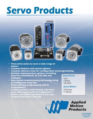
• Three drive series to cover a wide range of
motors
• Common features and control options
• Common software tools for configuration and programming
• Multiple communication options, including:
Ethernet, EtherNet/IP, RS-232/485 and
CANopen
• Easy system commissioning and tuning using
preconfigured setup files
• Point-and-click programming with Si
Programmer™
• Complex motion, multi-tasking, and third-
party HMI support with Q Programmer™
• Motors with NEMA and Metric frame sizes
• Torques from 0.84 to 64 in-lb
▪ SV7
▪ SVAC3
▪ BLuAC5
▪ M Series
▪ V Series
Servo Drives
Servo Motors
ELECTROMATE
Toll Free Phone (877) SERVO98
Toll Free Fax (877) SERV099
www.electromate.com
sales@electromate.com
Sold & Serviced By:
2. 2 15
▪ Pulse & direction
▪ CW/CCW pulse
▪ A/B quadrature
▪ Velocity (oscillator) mode
▪ Analog +/-10V torque, velocity, position
▪ Host commands (SCL)
▪ Quick TunerTM
software for setup
▪ Stand-alone operation
▪ Q ProgrammerTM
for complex motion
▪ Quick TunerTM
software for setup
▪ Conditional processing
▪ Math functions
▪ Multi-tasking
▪ Register manipulation
▪ Encoder following
▪ Third-party HMI compatibility
Control Options*
C
IP
C
IP
C
IP
C
IP
C
IP
C
IP
400W AC Powered Servo Drive
• Operates from 120 or 220 VAC
• Digital PID servo control
• Velocity and acceleration feedforward
minimize position error throughout
every move
• Digital DQ current loop provides wide
bandwidth, precise current control
• Sine commutation for smooth, quiet
motion
• PID output filter + derivative filter
eliminate system resonances
• Jerk filter provides jerk free “S curve”
motion
• Built-in regeneration (power dump)
circuit
• 100 Mbit Ethernet
• Flexible control options
• Q Programmable™ version
For more information, visit:
www.applied-motion.com/SVAC3
SVAC3 Accessories
RC-050 Regeneration
Clamp (for SV7)
The RC-050 regeneration
clamp is for use where
regeneration from the
motor may be excessive
for the power supply. In
these cases, the RC-050
is connected between the
drive and power supply and absorbs regenerated energy.
Power Supplies
Applied Motion offers two matched
power supplies for use with the
SV7 drives. A 24VDC 150W (part
number: PS150A24) and a 48VDC
320W version (part number:
PS320A48). These power supplies
have current over load capability
making them ideal for use with
servo drives.
Break Out Boards: BOB-1 and BOB-2
BOB-1 is for use with all drives and expands the
DB25F connector to screw terminals. BOB-2
is for use with the DB25M connector on the
BLuAC5-Si and -QE. A 3 foot cable included with
both models.
Braking resistor assembly - RA-100
For use with BLuAC5 dynamic braking and regeneration circuits.
*See back page for complete list of available model numbers.
Communications
Ethernet Port
▪ The Ethernet port on all SVAC3 drives is used for configuration,
programming, and streaming SCL and Q commands to one
or more drives across 100 Mbit Ethernet networks (TCP and
UDP).
EtherNet/IP option: SV7-IP-EE
▪ Allows drives to be commanded and queried over EtherNet/IP
industrial networks.
C
IP
C
IP
C
IP
▪ EtherNet/IP
▪ Connects to industry’s most popular PLC’s
▪ Same functions as Q model
ELECTROMATE
Toll Free Phone (877) SERVO98
Toll Free Fax (877) SERV099
www.electromate.com
sales@electromate.com
Sold & Serviced By:
3. 14
3
SVAC3 Dimensions
4.5
1.9
43
210FE
DCB
A9876
5
5.5
Inputs and Outputs
12 digital inputs
6 digital outputs
1 analog input
4 digital inputs
2 digital outputs
1 analog input
Servo Motor Extension Cables
ENCODER EXTENSION CABLE FOR V SERIES MOTORS
▪ VA-ENC-CA-06 - 6 ft
▪ VA-ENC-CA-10 - 10 ft
ENCODER EXTENSION CABLE FOR M SERIES MOTORS
▪ BLUENC-CA-04 - 4 ft
▪ BLUENC-CA-10 - 10 ft
▪ BLUENC-CA-20 - 20 ft
MOTOR EXTENSION CABLE FOR V SERIES MOTORS
▪ VA-MTR-CA-06 - 6 ft
▪ VA-MTR-CA-10 - 10 ft
MOTOR EXTENSION CABLE FOR M SERIES MOTORS
for use with BLuAC5 Drives
▪ BLUMTR-FA-04 - 4 ft
▪ BLUMTR-FA-10 - 10 ft
▪ BLUMTR-FA-20 - 20 ft
MOTOR EXTENSION CABLE FOR M SERIES MOTORS
for use with SV7 and SVAC3 Drives
▪ BLUMTR-CA-04 - 4 ft
▪ BLUMTR-CA-10 - 10 ft
▪ BLUMTR-CA-20 - 20 ft
Dimensions in inches
Not to scale
IP
C
IP
Q
C
IP
IP
C
IP
Q
C
IP
IP
C
IP
Q
C
IP
12 digital inputs
6 digital outputs
1 analog input
ELECTROMATE
Toll Free Phone (877) SERVO98
Toll Free Fax (877) SERV099
www.electromate.com
sales@electromate.com
Sold & Serviced By:
5. 12 5
SVAC3 Technical Specifications
POWER AMPLIFIER:
AMPLIFIER TYPE Digital MOSFET 16 kHz PWM
CURRENT CONTROL 4 quadrant d-q method
OUTPUT CURRENT SVAC3-120: 0.5 to 3.5 A rms continuous, 0.5 to 7.4 A rms peak (2 seconds max, I2t limiting)
SVAC3-220: 0.5 to 1.8 A rms continuous, 0.5 to 5.4 A rms peak (2 seconds max, I2t limiting)
INPUT POWER SVAC3-120: 108-132 VAC, 50-60 Hz
SVAC3-220: 108-242 VAC, 50-60 Hz"
PROTECTION Over-voltage, under-voltage, over-temp, motor/wiring shorts (phase-to-phase, phase-to-ground)
REGENERATION Built-in regeneration circuit, 10 watts max
AMBIENT TEMPERATURE 0 to 40 ºC (32 to 104 ºF), must be mounted to suitable heatsink with adequate ventilation
HUMIDITY 90% max, non-condensing
WEIGHT 22.4 oz
CONTROLLER:
NON-VOLATILE STORAGE Drive configuration and Q program stored in non-volatile memory
INPUTS/OUTPUTS: S
models
X1, X2 inputs: Optically isolated, differential, 5-24 VDC, minimum pulse width = 250 ns, maximum pulse
frequency = 2 MHz. Function: step & direction, CW/CCW step, A/B quadrature encoder
X3 input: Optically isolated, differential, 5-24 VDC. Function: motor enable
X4 input: Optically isolated, differential, 5-24 VDC. Function: alarm reset
Note: any input that is not assigned to a dedicated function can be used for a home or registration sensor
or for program branching
Y1 output: Optical Darlington, sinking or sourcing, 30 VDC max, 100 mA max. Function: brake relay
Y2 output: Optical Darlington, sinking or sourcing, 30 VDC max, 100 mA max. Function: fault, motion or
tach
Note: any output that is not assigned to a dedicated funtion is general purpose programmable
Analog input: Single-ended. Range (resolution) is software selectable 0-5 VDC (10 bits), +/-5 or 0-10 VDC
(11 bits), or +/-10 VDC (12 bits). Software configurable offset, deadband and filtering.
INPUTS/OUTPUTS: Q and
IP models
X1, X2 inputs: Optically isolated, differential, 5-24 VDC, minimum pulse width = 250 ns, maximum pulse
frequency = 2 MHz. Function: step & direction, CW/CCW step, A/B quadrature encoder
X3 input: Optically isolated, differential, 5-24 VDC. Function: motor enable
X4 input: Optically isolated, differential, 5-24 VDC. Function: alarm reset
IN1, IN2 inputs: Optically isolated, differential, 5-24 VDC. Function: jogging
IN3-IN6 inputs: Optically isolated, sinking w/ shared common, 12-24 VDC
IN7, IN8 inputs: Optically isolated, differential, 5-24 VDC. Function: CW and CCW limits
Note: any input that is not assigned to a dedicated function can be used for a home or registration sensor
or for program branching.
Y1 output: Optical Darlington, sinking or sourcing, 30 VDC max, 100 mA max. Function: brake relay
Y2 output: Optical Darlington, sinking or sourcing, 30 VDC max, 100 mA max. Function: fault
OUT1 output: Optical Darlington, sinking, 30 VDC max, 100 mA max. Function: motion or tach
OUT2, OUT3 outputs: Optical Darlington, sinking, 30 VDC max, 100 mA max
OUT4 output: Optical Darlington, sinking or sourcing, 30 VDC max, 100 mA max
Note: any output that is not assigned to a dedicated funtion is general purpose programmable
Analog input: Single-ended. Range (resolution) is software selectable 0-5 VDC (10 bits), +/-5 or 0-10 VDC
(11 bits), or +/-10 VDC (12 bits). Software configurable offset, deadband and filtering.
COMMUNICATION
INTERFACE
All models: Ethernet 100BASE-T, supports TCP and UDP
IP models only: EtherNet/IP industrial networking
ENCODER INTERFACE Differential line receivers for incremental encoder (A/B quadrature) feedback, up to 2 MHz. 400 cpr min
to 32,768 cpr max (1600 quadrature counts min to 131,072 quadrature counts max)
AGENCY APPROVALS RoHS
CE EN61800-3:2004, EN61800-5-1:2003
UL 508C
Software for All Drives
Si Programmer™
Intended for use in stand-alone applications, Si Programmer™ provides a user friendly, point-and-click, graphical inter-
face that doesn’t require any previous programming experience. Currently available on SV7 and BLuAC5 servo drives
only.
Q Programmer™
Q ProgrammerTM
is used to create and edit stand-alone
programs for Q version drives. These programs can in-
clude multi-tasking, math, register manipulation, encoder
following, and more.
Quick Tuner™
Used for setup and configuration of the drive. For more
information about Quick TunerTM
, visit the Applied Motion
Products website.
All software applications run on Windows 7, Windows Vista, XP, 2000, NT, ME, 98.
SV7 Technical Specifications (Continued)
CONTROLLER (CONT): All Models
INPUTS/OUTPUTS (CONT) Y1 output: Optical Darlington, NPN/sinking, 30 VDC max, 100 mA max. Function: brake relay
Y2 output: Optical Darlington, NPN/sinking, 30 VDC max, 100 mA max. Function: motion or tach
Y3 output: Optical Darlington, NPN/sinking, 30 VDC max, 100 mA max. Function: fault
Note: outputs Y1-Y3 have a shared common.
Y4 output: Optical Darlington, sinking or sourcing, 30 VDC max, 100 mA max
Note: any output that is not assigned to a dedicated funtion is general purpose programmable.
Analog input: Single-ended. Range (resolution) is software selectable 0-5 VDC (10 bits), +/-5 or 0-10
VDC (11 bits), or +/-10 VDC (12 bits). Software configurable offset, deadband and filtering.
COMMUNICATION INTER-
FACE
SV7-x-Ax: RS-232 for programming and serial communications
SV7-x-RE: RS-232 for programming and serial communications, RS-485 for serial communications
SV7-Q-EE: Ethernet for programming and serial communications
SV7-C-CE: RS-232 for programming, CANopen for communications
SV7-IP-EE: Ethernet for programming, EtherNet/IP for network communications"
ENCODER INTERFACE Differential line receivers for incremental encoder (A/B quadrature) feedback, up to 2 MHz. 400 cp
min to 32,768 cpr max (1600 quadrature counts min to 131,072 quadrature counts max)
AGENCY APPROVALS RoHS
CE EN61800-3:2004, EN61800-5-1:2003"
ELECTROMATE
Toll Free Phone (877) SERVO98
Toll Free Fax (877) SERV099
www.electromate.com
sales@electromate.com
Sold & Serviced By:
6. 6 11
▪ Si ProgrammerTM
point-and-click indexer
software with built-in Quick TunerTM
▪ User-friendly GUI
▪ I/O and motion programming
▪ Operator interface available (MMI-01 or
MMI-02)
▪ Pulse & direction
▪ CW/CCW pulse
▪ A/B quadrature
▪ Velocity (oscillator) mode
▪ Analog +/-10V torque, velocity, position
▪ Host commands (SCL)
▪ SiNet hub compatible
▪ Quick TunerTM
software for setup
▪ Stand-alone operation
▪ Q ProgrammerTM
for complex motion
▪ Quick TunerTM
software for setup
▪ Conditional processing
▪ Math functions
▪ Multi-tasking
▪ Register manipulation
▪ Encoder following
▪ Third-party HMI compatibility
▪ QE adds additional I/O
Control Options*
C
IP
C
IP
C
IP
C
IP
C
IP
C
IP
C
IP
C
IP
C
IP
1000W AC Powered Servo Drive
• Operates from 100 to 240 VAC, 1 or 3
phase
• Digital PID servo control
• Velocity and acceleration feedforward
minimize position error throughout
every move
• Digital DQ current loop provides wide
bandwidth, precise current control
• Sine commutation for smooth, quiet
motion
• PID output filter + derivative filter
eliminate system resonances
• Built-in regeneration (power dump)
circuit
• Dynamic braking
• RS-232, RS-485
• Flexible control options
• Si and Q Programmable™ versions
For more information, visit:
www.applied-motion.com
BLuAC5
SV7 Technical Specifications
POWER AMPLIFIER: All Models
AMPLIFIER TYPE Digital MOSFET 16 kHz PWM
CURRENT CONTROL 4 quadrant d-q method
OUTPUT CURRENT 0.5 to 7.0 A rms continuous, 0.5 to 14 A rms peak (2 seconds max, I2t limiting)
INPUT POWER 24-80 VDC (external power supply required)
PROTECTION Over-voltage, under-voltage, over-temp, motor/wiring shorts (phase-to-phase, phase-to-ground)
REGENERATION No internal regeneration circuit. RC-050 external regeneration clamp may be required for applications
with high load inertia and/or rapid deceleration
AMBIENT TEMPERATURE 0 to 40 ºC (32 to 104 ºF), must be mounted to suitable heatsink with adequate ventilation
HUMIDITY 90% max, non-condensing
WEIGHT 10 oz
CONTROLLER: All Models
NON-VOLATILE STORAGE Drive configuration and Q program stored in non-volatile memory
INPUTS/OUTPUTS X1, X2 inputs: Optically isolated, differential, 5 VDC, minimum pulse width = 250 ns, maximum pulse
frequency = 2 MHz. Function: step & direction, CW/CCW step, A/B quadrature encoder
X3 input: Optically isolated, sinking or sourcing, 12-24 VDC. Function: motor enable
X4 input: Optically isolated, sinking or sourcing, 12-24 VDC. Function: alarm reset
X5, X6 inputs: Optically isolated, sinking or sourcing, 12-24 VDC. Function: CW and CCW jog inputs
Note: inputs X3-X6 have a shared common.
X7, X8 inputs: Optically isolated, differential, 12-24 VDC. Function: CW and CCW limits
Note: any input that is not assigned to a dedicated function can be used for a home or registration sensor
or for program branching.
Recommended Motors (220V Models)Torque Curves for SV7 at 48 VDC
0
50
100
150
200
250
0 1000 2000 3000 4000 5000 6000 7000 8000
Torque(oz-in)
Speed (RPM)
V0250-214-B 60VDC Peak
V0250-214-B 60VDC Cont
V0250-214-B 48VDC Peak
V0250-214-B 48VDC Cont
V0200-214-B 48VDC Peak
V0200-214-B 48VDC Cont
V0100-214-B 48VDC Peak
V0100-214-B 48VDC Cont
V0050-214-A 48VDC Peak
V0050-214-A 48VDC Cont
*See back page for complete list of available model numbers.
Communications
RS-232 port
Standard on all drives
▪ The RS-232 port is used for configuration, programming, and
sending SCL and Q commands to a single drive.
RS-485 port
Standard on all drives
▪ The RS-485 port can be used to stream SCL and Q
commands to one or more drives across a serial network.
More curves available at www.applied-motion.com
Continued on page 12
ELECTROMATE
Toll Free Phone (877) SERVO98
Toll Free Fax (877) SERV099
www.electromate.com
sales@electromate.com
Sold & Serviced By:
7. 2.70
1.32
7.8
4.85
7.4
Si2035
B–
B+
A–
A+
MOTOR
10 7
Recommended Motors (220V Models)
SV7 Dimensions Inputs and Outputs
3.0
1.125
6X SLOT 0.16
WIDE, FULL R
3.0
1.75
5.0
6X SLOT 0.16
WIDE, FULL R0.663
1.98
0.61
4.74
Dimensions in Inches
Not to scale
8 digital inputs
4 digital outputs
2 analog inputs
8 digital inputs
4 digital outputs
2 analog inputs
8 digital inputs
4 digital outputs
2 analog inputs
IP
C
IP
Q
C
IP
IP
C
IP
Q
C
IP
8 digital inputs
4 digital outputs
Torque Curves for SV7 at 24 VDC
250 V0250-214-B 24VDC Peak
V0250-214-B 24VDC Cont
200
V0200-214-B 24VDC Peak
V0200-214-B 24VDC Cont
V0100-214-B 24VDC Peak
150
-in)
V0100-214-B 24VDC Cont
V0050-214-A 24VDC Peak
V0050-214-A 24VDC Cont
100
Torque(oz-
50
00
0 1000 2000 3000 4000 5000 6000 7000 8000
Speed (RPM)
BLuAC5 Dimensions
Dimensions in Inches
Not to scale
Inputs and Outputs
7 digital inputs
3 digital outputs
2 analog inputs
7 digital inputs
3 digital outputs
2 analog inputs
IP
C
IP
Q
C
IP
IP
C
IP
Q
C
IP
IP
C
IP
Q
C
IP
15 digital inputs
7 digital outputs
15 digital inputs
7 digital outputs
3 analog inputs
Torque Curves for BLuAC5
0
200
400
600
800
1000
1200
0 500 1000 1500 2000 2500 3000 3500 4000 4500 5000
Torque(oz-in)
Speed (RPM)
M0750-102-5 220VAC Peak M0750-102-5 220VAC Cont
M0600-102-5 220VAC Peak M0600-102-5 220VAC Cont
M0400-102-5 220VAC Peak M0400-102-5 220VAC Cont
M0400-101-4 120VAC Peak M0400-101-4 120VAC Cont
More curves available at www.applied-motion.com
IP
C
Q
C
IP
IP
C
IP
Q
C
IP
IP
C
Q
C
IP
IP
C
IP
Q
C
IP
IP
C
IP
Q
C
IP
8 digital inputs
4 digital outputs
2 analog inputs
IP
C
Q
C
IP
IP
C
Q
C
IP
IP
C
IP
Q
C
IP
IP
C
IP
Q
C
IP
ELECTROMATE
Toll Free Phone (877) SERVO98
Toll Free Fax (877) SERV099
www.electromate.com
sales@electromate.com
Sold & Serviced By:
8. CONTROLLER:
NON-VOLATILE STORAGE Drive configuration and programs stored in non-volatile memory
INPUTS/OUTPUTS: S and
Q models
X1, X2 inputs: Optically isolated, differential, 5 VDC
X3-X7 inputs: Optically isolated, single-ended w/ shared common, 12-24 VDC
Y1-Y3 outputs: Optical Darlington, sinking w/ shared common, 30 VDC max, 100 mA max
Analog inputs: Two single-ended inputs can be wired together as one differential input. Range is software
selectable 0-5 VDC, +/-5, 0-10 VDC, or +/-10 VDC. Software configurable offset, deadband and filtering
on differential input only
INPUTS/OUTPUTS: QE
and Si models
X1, X2 inputs: Optically isolated, differential, 5 VDC
X3-X7 inputs: Optically isolated, single-ended w/ shared common, 12-24 VDC
IN1-IN6 inputs: Optically isolated, single-ended w/ shared common, 12-24 VDC
IN7, IN8 inputs: Optically isolated, differential, 12-24 VDC
Y1-Y3 outputs: Optical Darlington, sinking w/ shared common, 30 VDC max, 100 mA max
OUT1-OUT4 outputs: Optical Darlington, sinking or sourcing, 30 VDC max, 100 mA max
Analog inputs: Two single-ended inputs can be wired together as one differential input. Range is software
selectable 0-5 VDC, +/-5, 0-10 VDC, or +/-10 VDC. Software configurable offset, deadband and filtering
on differential input only.
Note: Si Programming does not support the analog input(s).
COMMUNICATION
INTERFACE
RS-232 for configuration, programming and serial communications to a single drive
RS-485 for serial communications to one or more drives on a serial network
ENCODER INTERFACE Differential line receivers for incremental encoder (A/B quadrature) feedback, up to 2 MHz. 50 cpr min to
8192 cpr max (200 quadrature counts min to 32,768 quadrature counts max)
AGENCY APPROVALS RoHS
CE
8 9
▪ Si ProgrammerTM
with built-in Quick TunerTM
▪ Point-and-click indexing software
▪ User-friendly GUI
▪ I/O and motion programming
▪ Operator interface available (MMI-01 or MMI-02)
▪ Pulse & direction
▪ CW/CCW pulse
▪ A/B quadrature
▪ Velocity (oscillator) mode
▪ Analog +/-10V torque, velocity, position
▪ Host commands (SCL)
▪ SiNet Hub compatible
▪ Quick TunerTM
software for setup
▪ Stand-alone operation
▪ Q ProgrammerTM
for complex motion
▪ Quick TunerTM
software for setup
▪ Conditional processing
▪ Math functions
▪ Multi-tasking
▪ Register manipulation
▪ Encoder following
▪ Third-party HMI compatibility
Control Options*
Communications
C
IP
C
IP
C
IP
C
IP
C
IP
C
IP
C
IP
C
IP
C
IP
C
IP
C
IP
C
IP
▪ CANopen protocols DS301 and DSP402
▪ Profile Position, Profile Velocity, and
Homing modes
▪ Up to 127 axes per channel
▪ Execute stored Q programs
300W DC Powered Servo Drive
• Operates from 24 to 80 VDC
• Digital PID servo control
• Velocity and acceleration feedforward
minimize position error throughout
every move
• Digital DQ current loop provides wide
bandwidth, precise current control
• Sine commutation for smooth, quiet
motion
• PID output filter + derivative filter
eliminate system resonances
• Jerk filter provides jerk free “S curve”
motion
• RS-232, RS-485, CANopen, Ethernet
• Flexible control options
• Si and Q Programmable™ versions
For more information go to
www.applied-motion.com/SV
Ethernet option: SV7-Q-EE
▪ The Ethernet option board allows the SV7-Q-EE to be
commanded and queried over standard 100Mbit Ethernet
using the SCL and Q languages.
CANopen option: SV7-C-CE
▪ The CANopen option board used with the SV7-C-CE allows the
drive to be connected to a CANopen network along with other
CANopen drives. Drives can be controlled and interrogated
over the network.
RS-485 option: SV7-Q-RE, SV7-S-RE
▪ The RS-485 option board adds the ability to stream SCL and
Q commands to one or more drives on a serial network.
RS-232 port: standard on all but Ethernet drives
Example: SV7-S-AF
▪ The RS-232 port is used for configuration, programming, and
serial communications with a single drive.
EtherNet/IP option: SV7-IP-EE
▪ Allows drives to be commanded and queried over EtherNet/IP
industrial networks.
SV7BLuAC5 Technical Specifications
POWER AMPLIFIER:
AMPLIFIER TYPE 3-phase sinusoidal PWM switching at 16 kHz
CURRENT CONTROL 4 quadrant d-q method
OUTPUT CURRENT Up to 5 A rms continuous, up to 15 A rms peak (2 seconds max, I2t limiting)
INPUT POWER 90-260 VAC, 50/60 Hz, 1-phase or 3-phase
PROTECTION Over-voltage (400 VDC on DC bus), under-voltage (100 VDC on DC bus), over-temp (75 ºC), motor/wiring
shorts (phase-to-phase, phase-to-ground), regeneration error (based on regeneration values input by
user), encoder failure (differential encoders only), Hall sensor failure
REGENERATION 50 Watt internal shunt resistor, connector for external high-power shunt resistor
AMBIENT TEMPERATURE 0 to 40 ºC (32 to 104 ºF), must be mounted to suitable heatsink with adequate ventilation
HUMIDITY 90% max, non-condensing
WEIGHT S and Q models: 35.1 oz
QE and Si models: 44 oz
*See back page for complete list of available model numbers.
C
IP
C
IP
C
IP
▪ EtherNet/IP
▪ Connects to industry’s most popular PLC’s
▪ Same functions as Q model
ELECTROMATE
Toll Free Phone (877) SERVO98
Toll Free Fax (877) SERV099
www.electromate.com
sales@electromate.com
Sold & Serviced By:
9. CONTROLLER:
NON-VOLATILE STORAGE Drive configuration and programs stored in non-volatile memory
INPUTS/OUTPUTS: S and
Q models
X1, X2 inputs: Optically isolated, differential, 5 VDC
X3-X7 inputs: Optically isolated, single-ended w/ shared common, 12-24 VDC
Y1-Y3 outputs: Optical Darlington, sinking w/ shared common, 30 VDC max, 100 mA max
Analog inputs: Two single-ended inputs can be wired together as one differential input. Range is software
selectable 0-5 VDC, +/-5, 0-10 VDC, or +/-10 VDC. Software configurable offset, deadband and filtering
on differential input only
INPUTS/OUTPUTS: QE
and Si models
X1, X2 inputs: Optically isolated, differential, 5 VDC
X3-X7 inputs: Optically isolated, single-ended w/ shared common, 12-24 VDC
IN1-IN6 inputs: Optically isolated, single-ended w/ shared common, 12-24 VDC
IN7, IN8 inputs: Optically isolated, differential, 12-24 VDC
Y1-Y3 outputs: Optical Darlington, sinking w/ shared common, 30 VDC max, 100 mA max
OUT1-OUT4 outputs: Optical Darlington, sinking or sourcing, 30 VDC max, 100 mA max
Analog inputs: Two single-ended inputs can be wired together as one differential input. Range is software
selectable 0-5 VDC, +/-5, 0-10 VDC, or +/-10 VDC. Software configurable offset, deadband and filtering
on differential input only.
Note: Si Programming does not support the analog input(s).
COMMUNICATION
INTERFACE
RS-232 for configuration, programming and serial communications to a single drive
RS-485 for serial communications to one or more drives on a serial network
ENCODER INTERFACE Differential line receivers for incremental encoder (A/B quadrature) feedback, up to 2 MHz. 50 cpr min to
8192 cpr max (200 quadrature counts min to 32,768 quadrature counts max)
AGENCY APPROVALS RoHS
CE
8 9
▪ Si ProgrammerTM
with built-in Quick TunerTM
▪ Point-and-click indexing software
▪ User-friendly GUI
▪ I/O and motion programming
▪ Operator interface available (MMI-01 or MMI-02)
▪ Pulse & direction
▪ CW/CCW pulse
▪ A/B quadrature
▪ Velocity (oscillator) mode
▪ Analog +/-10V torque, velocity, position
▪ Host commands (SCL)
▪ SiNet Hub compatible
▪ Quick TunerTM
software for setup
▪ Stand-alone operation
▪ Q ProgrammerTM
for complex motion
▪ Quick TunerTM
software for setup
▪ Conditional processing
▪ Math functions
▪ Multi-tasking
▪ Register manipulation
▪ Encoder following
▪ Third-party HMI compatibility
Control Options*
Communications
C
IP
C
IP
C
IP
C
IP
C
IP
C
IP
C
IP
C
IP
C
IP
C
IP
C
IP
C
IP
▪ CANopen protocols DS301 and DSP402
▪ Profile Position, Profile Velocity, and
Homing modes
▪ Up to 127 axes per channel
▪ Execute stored Q programs
300W DC Powered Servo Drive
• Operates from 24 to 80 VDC
• Digital PID servo control
• Velocity and acceleration feedforward
minimize position error throughout
every move
• Digital DQ current loop provides wide
bandwidth, precise current control
• Sine commutation for smooth, quiet
motion
• PID output filter + derivative filter
eliminate system resonances
• Jerk filter provides jerk free “S curve”
motion
• RS-232, RS-485, CANopen, Ethernet
• Flexible control options
• Si and Q Programmable™ versions
For more information go to
www.applied-motion.com/SV
Ethernet option: SV7-Q-EE
▪ The Ethernet option board allows the SV7-Q-EE to be
commanded and queried over standard 100Mbit Ethernet
using the SCL and Q languages.
CANopen option: SV7-C-CE
▪ The CANopen option board used with the SV7-C-CE allows the
drive to be connected to a CANopen network along with other
CANopen drives. Drives can be controlled and interrogated
over the network.
RS-485 option: SV7-Q-RE, SV7-S-RE
▪ The RS-485 option board adds the ability to stream SCL and
Q commands to one or more drives on a serial network.
RS-232 port: standard on all but Ethernet drives
Example: SV7-S-AF
▪ The RS-232 port is used for configuration, programming, and
serial communications with a single drive.
EtherNet/IP option: SV7-IP-EE
▪ Allows drives to be commanded and queried over EtherNet/IP
industrial networks.
SV7BLuAC5 Technical Specifications
POWER AMPLIFIER:
AMPLIFIER TYPE 3-phase sinusoidal PWM switching at 16 kHz
CURRENT CONTROL 4 quadrant d-q method
OUTPUT CURRENT Up to 5 A rms continuous, up to 15 A rms peak (2 seconds max, I2t limiting)
INPUT POWER 90-260 VAC, 50/60 Hz, 1-phase or 3-phase
PROTECTION Over-voltage (400 VDC on DC bus), under-voltage (100 VDC on DC bus), over-temp (75 ºC), motor/wiring
shorts (phase-to-phase, phase-to-ground), regeneration error (based on regeneration values input by
user), encoder failure (differential encoders only), Hall sensor failure
REGENERATION 50 Watt internal shunt resistor, connector for external high-power shunt resistor
AMBIENT TEMPERATURE 0 to 40 ºC (32 to 104 ºF), must be mounted to suitable heatsink with adequate ventilation
HUMIDITY 90% max, non-condensing
WEIGHT S and Q models: 35.1 oz
QE and Si models: 44 oz
*See back page for complete list of available model numbers.
C
IP
C
IP
C
IP
▪ EtherNet/IP
▪ Connects to industry’s most popular PLC’s
▪ Same functions as Q model
ELECTROMATE
Toll Free Phone (877) SERVO98
Toll Free Fax (877) SERV099
www.electromate.com
sales@electromate.com
Sold & Serviced By:
10. 2.70
1.32
7.8
4.85
7.4
Si2035
B–
B+
A–
A+
MOTOR
10 7
Recommended Motors (220V Models)
SV7 Dimensions Inputs and Outputs
3.0
1.125
6X SLOT 0.16
WIDE, FULL R
3.0
1.75
5.0
6X SLOT 0.16
WIDE, FULL R0.663
1.98
0.61
4.74
Dimensions in Inches
Not to scale
8 digital inputs
4 digital outputs
2 analog inputs
8 digital inputs
4 digital outputs
2 analog inputs
8 digital inputs
4 digital outputs
2 analog inputs
IP
C
IP
Q
C
IP
IP
C
IP
Q
C
IP
8 digital inputs
4 digital outputs
Torque Curves for SV7 at 24 VDC
250 V0250-214-B 24VDC Peak
V0250-214-B 24VDC Cont
200
V0200-214-B 24VDC Peak
V0200-214-B 24VDC Cont
V0100-214-B 24VDC Peak
150
-in)
V0100-214-B 24VDC Cont
V0050-214-A 24VDC Peak
V0050-214-A 24VDC Cont
100
Torque(oz-
50
00
0 1000 2000 3000 4000 5000 6000 7000 8000
Speed (RPM)
BLuAC5 Dimensions
Dimensions in Inches
Not to scale
Inputs and Outputs
7 digital inputs
3 digital outputs
2 analog inputs
7 digital inputs
3 digital outputs
2 analog inputs
IP
C
IP
Q
C
IP
IP
C
IP
Q
C
IP
IP
C
IP
Q
C
IP
15 digital inputs
7 digital outputs
15 digital inputs
7 digital outputs
3 analog inputs
Torque Curves for BLuAC5
0
200
400
600
800
1000
1200
0 500 1000 1500 2000 2500 3000 3500 4000 4500 5000
Torque(oz-in)
Speed (RPM)
M0750-102-5 220VAC Peak M0750-102-5 220VAC Cont
M0600-102-5 220VAC Peak M0600-102-5 220VAC Cont
M0400-102-5 220VAC Peak M0400-102-5 220VAC Cont
M0400-101-4 120VAC Peak M0400-101-4 120VAC Cont
More curves available at www.applied-motion.com
IP
C
Q
C
IP
IP
C
IP
Q
C
IP
IP
C
Q
C
IP
IP
C
IP
Q
C
IP
IP
C
IP
Q
C
IP
8 digital inputs
4 digital outputs
2 analog inputs
IP
C
Q
C
IP
IP
C
Q
C
IP
IP
C
IP
Q
C
IP
IP
C
IP
Q
C
IP
ELECTROMATE
Toll Free Phone (877) SERVO98
Toll Free Fax (877) SERV099
www.electromate.com
sales@electromate.com
Sold & Serviced By:
11. 6 11
▪ Si ProgrammerTM
point-and-click indexer
software with built-in Quick TunerTM
▪ User-friendly GUI
▪ I/O and motion programming
▪ Operator interface available (MMI-01 or
MMI-02)
▪ Pulse & direction
▪ CW/CCW pulse
▪ A/B quadrature
▪ Velocity (oscillator) mode
▪ Analog +/-10V torque, velocity, position
▪ Host commands (SCL)
▪ SiNet hub compatible
▪ Quick TunerTM
software for setup
▪ Stand-alone operation
▪ Q ProgrammerTM
for complex motion
▪ Quick TunerTM
software for setup
▪ Conditional processing
▪ Math functions
▪ Multi-tasking
▪ Register manipulation
▪ Encoder following
▪ Third-party HMI compatibility
▪ QE adds additional I/O
Control Options*
C
IP
C
IP
C
IP
C
IP
C
IP
C
IP
C
IP
C
IP
C
IP
1000W AC Powered Servo Drive
• Operates from 100 to 240 VAC, 1 or 3
phase
• Digital PID servo control
• Velocity and acceleration feedforward
minimize position error throughout
every move
• Digital DQ current loop provides wide
bandwidth, precise current control
• Sine commutation for smooth, quiet
motion
• PID output filter + derivative filter
eliminate system resonances
• Built-in regeneration (power dump)
circuit
• Dynamic braking
• RS-232, RS-485
• Flexible control options
• Si and Q Programmable™ versions
For more information, visit:
www.applied-motion.com
BLuAC5
SV7 Technical Specifications
POWER AMPLIFIER: All Models
AMPLIFIER TYPE Digital MOSFET 16 kHz PWM
CURRENT CONTROL 4 quadrant d-q method
OUTPUT CURRENT 0.5 to 7.0 A rms continuous, 0.5 to 14 A rms peak (2 seconds max, I2t limiting)
INPUT POWER 24-80 VDC (external power supply required)
PROTECTION Over-voltage, under-voltage, over-temp, motor/wiring shorts (phase-to-phase, phase-to-ground)
REGENERATION No internal regeneration circuit. RC-050 external regeneration clamp may be required for applications
with high load inertia and/or rapid deceleration
AMBIENT TEMPERATURE 0 to 40 ºC (32 to 104 ºF), must be mounted to suitable heatsink with adequate ventilation
HUMIDITY 90% max, non-condensing
WEIGHT 10 oz
CONTROLLER: All Models
NON-VOLATILE STORAGE Drive configuration and Q program stored in non-volatile memory
INPUTS/OUTPUTS X1, X2 inputs: Optically isolated, differential, 5 VDC, minimum pulse width = 250 ns, maximum pulse
frequency = 2 MHz. Function: step & direction, CW/CCW step, A/B quadrature encoder
X3 input: Optically isolated, sinking or sourcing, 12-24 VDC. Function: motor enable
X4 input: Optically isolated, sinking or sourcing, 12-24 VDC. Function: alarm reset
X5, X6 inputs: Optically isolated, sinking or sourcing, 12-24 VDC. Function: CW and CCW jog inputs
Note: inputs X3-X6 have a shared common.
X7, X8 inputs: Optically isolated, differential, 12-24 VDC. Function: CW and CCW limits
Note: any input that is not assigned to a dedicated function can be used for a home or registration sensor
or for program branching.
Recommended Motors (220V Models)Torque Curves for SV7 at 48 VDC
0
50
100
150
200
250
0 1000 2000 3000 4000 5000 6000 7000 8000
Torque(oz-in)
Speed (RPM)
V0250-214-B 60VDC Peak
V0250-214-B 60VDC Cont
V0250-214-B 48VDC Peak
V0250-214-B 48VDC Cont
V0200-214-B 48VDC Peak
V0200-214-B 48VDC Cont
V0100-214-B 48VDC Peak
V0100-214-B 48VDC Cont
V0050-214-A 48VDC Peak
V0050-214-A 48VDC Cont
*See back page for complete list of available model numbers.
Communications
RS-232 port
Standard on all drives
▪ The RS-232 port is used for configuration, programming, and
sending SCL and Q commands to a single drive.
RS-485 port
Standard on all drives
▪ The RS-485 port can be used to stream SCL and Q
commands to one or more drives across a serial network.
More curves available at www.applied-motion.com
Continued on page 12
ELECTROMATE
Toll Free Phone (877) SERVO98
Toll Free Fax (877) SERV099
www.electromate.com
sales@electromate.com
Sold & Serviced By:
12. 12 5
SVAC3 Technical Specifications
POWER AMPLIFIER:
AMPLIFIER TYPE Digital MOSFET 16 kHz PWM
CURRENT CONTROL 4 quadrant d-q method
OUTPUT CURRENT SVAC3-120: 0.5 to 3.5 A rms continuous, 0.5 to 7.4 A rms peak (2 seconds max, I2t limiting)
SVAC3-220: 0.5 to 1.8 A rms continuous, 0.5 to 5.4 A rms peak (2 seconds max, I2t limiting)
INPUT POWER SVAC3-120: 108-132 VAC, 50-60 Hz
SVAC3-220: 108-242 VAC, 50-60 Hz"
PROTECTION Over-voltage, under-voltage, over-temp, motor/wiring shorts (phase-to-phase, phase-to-ground)
REGENERATION Built-in regeneration circuit, 10 watts max
AMBIENT TEMPERATURE 0 to 40 ºC (32 to 104 ºF), must be mounted to suitable heatsink with adequate ventilation
HUMIDITY 90% max, non-condensing
WEIGHT 22.4 oz
CONTROLLER:
NON-VOLATILE STORAGE Drive configuration and Q program stored in non-volatile memory
INPUTS/OUTPUTS: S
models
X1, X2 inputs: Optically isolated, differential, 5-24 VDC, minimum pulse width = 250 ns, maximum pulse
frequency = 2 MHz. Function: step & direction, CW/CCW step, A/B quadrature encoder
X3 input: Optically isolated, differential, 5-24 VDC. Function: motor enable
X4 input: Optically isolated, differential, 5-24 VDC. Function: alarm reset
Note: any input that is not assigned to a dedicated function can be used for a home or registration sensor
or for program branching
Y1 output: Optical Darlington, sinking or sourcing, 30 VDC max, 100 mA max. Function: brake relay
Y2 output: Optical Darlington, sinking or sourcing, 30 VDC max, 100 mA max. Function: fault, motion or
tach
Note: any output that is not assigned to a dedicated funtion is general purpose programmable
Analog input: Single-ended. Range (resolution) is software selectable 0-5 VDC (10 bits), +/-5 or 0-10 VDC
(11 bits), or +/-10 VDC (12 bits). Software configurable offset, deadband and filtering.
INPUTS/OUTPUTS: Q and
IP models
X1, X2 inputs: Optically isolated, differential, 5-24 VDC, minimum pulse width = 250 ns, maximum pulse
frequency = 2 MHz. Function: step & direction, CW/CCW step, A/B quadrature encoder
X3 input: Optically isolated, differential, 5-24 VDC. Function: motor enable
X4 input: Optically isolated, differential, 5-24 VDC. Function: alarm reset
IN1, IN2 inputs: Optically isolated, differential, 5-24 VDC. Function: jogging
IN3-IN6 inputs: Optically isolated, sinking w/ shared common, 12-24 VDC
IN7, IN8 inputs: Optically isolated, differential, 5-24 VDC. Function: CW and CCW limits
Note: any input that is not assigned to a dedicated function can be used for a home or registration sensor
or for program branching.
Y1 output: Optical Darlington, sinking or sourcing, 30 VDC max, 100 mA max. Function: brake relay
Y2 output: Optical Darlington, sinking or sourcing, 30 VDC max, 100 mA max. Function: fault
OUT1 output: Optical Darlington, sinking, 30 VDC max, 100 mA max. Function: motion or tach
OUT2, OUT3 outputs: Optical Darlington, sinking, 30 VDC max, 100 mA max
OUT4 output: Optical Darlington, sinking or sourcing, 30 VDC max, 100 mA max
Note: any output that is not assigned to a dedicated funtion is general purpose programmable
Analog input: Single-ended. Range (resolution) is software selectable 0-5 VDC (10 bits), +/-5 or 0-10 VDC
(11 bits), or +/-10 VDC (12 bits). Software configurable offset, deadband and filtering.
COMMUNICATION
INTERFACE
All models: Ethernet 100BASE-T, supports TCP and UDP
IP models only: EtherNet/IP industrial networking
ENCODER INTERFACE Differential line receivers for incremental encoder (A/B quadrature) feedback, up to 2 MHz. 400 cpr min
to 32,768 cpr max (1600 quadrature counts min to 131,072 quadrature counts max)
AGENCY APPROVALS RoHS
CE EN61800-3:2004, EN61800-5-1:2003
UL 508C
Software for All Drives
Si Programmer™
Intended for use in stand-alone applications, Si Programmer™ provides a user friendly, point-and-click, graphical inter-
face that doesn’t require any previous programming experience. Currently available on SV7 and BLuAC5 servo drives
only.
Q Programmer™
Q ProgrammerTM
is used to create and edit stand-alone
programs for Q version drives. These programs can in-
clude multi-tasking, math, register manipulation, encoder
following, and more.
Quick Tuner™
Used for setup and configuration of the drive. For more
information about Quick TunerTM
, visit the Applied Motion
Products website.
All software applications run on Windows 7, Windows Vista, XP, 2000, NT, ME, 98.
SV7 Technical Specifications (Continued)
CONTROLLER (CONT): All Models
INPUTS/OUTPUTS (CONT) Y1 output: Optical Darlington, NPN/sinking, 30 VDC max, 100 mA max. Function: brake relay
Y2 output: Optical Darlington, NPN/sinking, 30 VDC max, 100 mA max. Function: motion or tach
Y3 output: Optical Darlington, NPN/sinking, 30 VDC max, 100 mA max. Function: fault
Note: outputs Y1-Y3 have a shared common.
Y4 output: Optical Darlington, sinking or sourcing, 30 VDC max, 100 mA max
Note: any output that is not assigned to a dedicated funtion is general purpose programmable.
Analog input: Single-ended. Range (resolution) is software selectable 0-5 VDC (10 bits), +/-5 or 0-10
VDC (11 bits), or +/-10 VDC (12 bits). Software configurable offset, deadband and filtering.
COMMUNICATION INTER-
FACE
SV7-x-Ax: RS-232 for programming and serial communications
SV7-x-RE: RS-232 for programming and serial communications, RS-485 for serial communications
SV7-Q-EE: Ethernet for programming and serial communications
SV7-C-CE: RS-232 for programming, CANopen for communications
SV7-IP-EE: Ethernet for programming, EtherNet/IP for network communications"
ENCODER INTERFACE Differential line receivers for incremental encoder (A/B quadrature) feedback, up to 2 MHz. 400 cp
min to 32,768 cpr max (1600 quadrature counts min to 131,072 quadrature counts max)
AGENCY APPROVALS RoHS
CE EN61800-3:2004, EN61800-5-1:2003"
ELECTROMATE
Toll Free Phone (877) SERVO98
Toll Free Fax (877) SERV099
www.electromate.com
sales@electromate.com
Sold & Serviced By:
14. 14
3
SVAC3 Dimensions
4.5
1.9
43
210FE
DCB
A9876
5
5.5
Inputs and Outputs
12 digital inputs
6 digital outputs
1 analog input
4 digital inputs
2 digital outputs
1 analog input
Servo Motor Extension Cables
ENCODER EXTENSION CABLE FOR V SERIES MOTORS
▪ VA-ENC-CA-06 - 6 ft
▪ VA-ENC-CA-10 - 10 ft
ENCODER EXTENSION CABLE FOR M SERIES MOTORS
▪ BLUENC-CA-04 - 4 ft
▪ BLUENC-CA-10 - 10 ft
▪ BLUENC-CA-20 - 20 ft
MOTOR EXTENSION CABLE FOR V SERIES MOTORS
▪ VA-MTR-CA-06 - 6 ft
▪ VA-MTR-CA-10 - 10 ft
MOTOR EXTENSION CABLE FOR M SERIES MOTORS
for use with BLuAC5 Drives
▪ BLUMTR-FA-04 - 4 ft
▪ BLUMTR-FA-10 - 10 ft
▪ BLUMTR-FA-20 - 20 ft
MOTOR EXTENSION CABLE FOR M SERIES MOTORS
for use with SV7 and SVAC3 Drives
▪ BLUMTR-CA-04 - 4 ft
▪ BLUMTR-CA-10 - 10 ft
▪ BLUMTR-CA-20 - 20 ft
Dimensions in inches
Not to scale
IP
C
IP
Q
C
IP
IP
C
IP
Q
C
IP
IP
C
IP
Q
C
IP
12 digital inputs
6 digital outputs
1 analog input
ELECTROMATE
Toll Free Phone (877) SERVO98
Toll Free Fax (877) SERV099
www.electromate.com
sales@electromate.com
Sold & Serviced By:
15. 2 15
▪ Pulse & direction
▪ CW/CCW pulse
▪ A/B quadrature
▪ Velocity (oscillator) mode
▪ Analog +/-10V torque, velocity, position
▪ Host commands (SCL)
▪ Quick TunerTM
software for setup
▪ Stand-alone operation
▪ Q ProgrammerTM
for complex motion
▪ Quick TunerTM
software for setup
▪ Conditional processing
▪ Math functions
▪ Multi-tasking
▪ Register manipulation
▪ Encoder following
▪ Third-party HMI compatibility
Control Options*
C
IP
C
IP
C
IP
C
IP
C
IP
C
IP
400W AC Powered Servo Drive
• Operates from 120 or 220 VAC
• Digital PID servo control
• Velocity and acceleration feedforward
minimize position error throughout
every move
• Digital DQ current loop provides wide
bandwidth, precise current control
• Sine commutation for smooth, quiet
motion
• PID output filter + derivative filter
eliminate system resonances
• Jerk filter provides jerk free “S curve”
motion
• Built-in regeneration (power dump)
circuit
• 100 Mbit Ethernet
• Flexible control options
• Q Programmable™ version
For more information, visit:
www.applied-motion.com/SVAC3
SVAC3 Accessories
RC-050 Regeneration
Clamp (for SV7)
The RC-050 regeneration
clamp is for use where
regeneration from the
motor may be excessive
for the power supply. In
these cases, the RC-050
is connected between the
drive and power supply and absorbs regenerated energy.
Power Supplies
Applied Motion offers two matched
power supplies for use with the
SV7 drives. A 24VDC 150W (part
number: PS150A24) and a 48VDC
320W version (part number:
PS320A48). These power supplies
have current over load capability
making them ideal for use with
servo drives.
Break Out Boards: BOB-1 and BOB-2
BOB-1 is for use with all drives and expands the
DB25F connector to screw terminals. BOB-2
is for use with the DB25M connector on the
BLuAC5-Si and -QE. A 3 foot cable included with
both models.
Braking resistor assembly - RA-100
For use with BLuAC5 dynamic braking and regeneration circuits.
*See back page for complete list of available model numbers.
Communications
Ethernet Port
▪ The Ethernet port on all SVAC3 drives is used for configuration,
programming, and streaming SCL and Q commands to one
or more drives across 100 Mbit Ethernet networks (TCP and
UDP).
EtherNet/IP option: SV7-IP-EE
▪ Allows drives to be commanded and queried over EtherNet/IP
industrial networks.
C
IP
C
IP
C
IP
▪ EtherNet/IP
▪ Connects to industry’s most popular PLC’s
▪ Same functions as Q model
ELECTROMATE
Toll Free Phone (877) SERVO98
Toll Free Fax (877) SERV099
www.electromate.com
sales@electromate.com
Sold & Serviced By:
16. #006BB3
#FFFFFF
#383838 85%k
76%C
68%M
67%Y
90%K
Servo Products
DISTRIBUTED BY:
16 925-0008-B 9-2011
Model
Numbers
QProgramming
SiProgramming
RS-232
RS-422/485
Ethernet
EtherNet/IP
CANopen
EncoderOutput
SVAC3-S-E120 X
SVAC3-S-E220 X
SVAC3-Q-E120 X X
SVAC3-Q-E220 X X
SVAC3-IP-E120 X X X
SVAC3-IP-E220 X X X
BLuAC5-S X X X
BLuAC5-Q X X X X
BLuAC5-QE X X X X
BLuAC5-Si X X X X
SV7-S-AE X
SV7-S-AF X X
SV7-S-RE X X
SV7-Q-AE X X
SV7-Q-AF X X X
SV7-Q-RE X X X
SV7-Q-EE X X
SV7-Si-AE X X
SV7-Si-AF X X X
SV7-C-CE X X
SV7-IP-EE X X X
Servo Drive Model Numbers
SVAC3-S-E120
Control
S = Basic version
Q = Q Programming
IP = EtherNet/IP
Feedback
E = Encoder board
Series
SVAC Servo Series
Input Voltage
120 = 120VAC
220 = 220VAC
3 = 3.5A cont, 7.4A peak, 120VAC
1.8A cont, 5.4A peak, 220VAC
SV7-S-RE
Output Current
7 = 7.0 Cont, 14A Peak
Control
S = Basic version
Q = Q Programming
Si = Si Programming
C = CANopen
IP = EtherNet/IP
Feedback
E = Encoder board (standard)
F = Motion Controller Feedback
(MCF) board
Communications
A = RS-232 (standard)
R = RS-485 (optional)
C = CANopen (optional)
(requires C control option)
E = Ethernet (optional)
(requires Q or IP control option)
Series
SV Servo Series
BLuAC5-Si
Output Current
5= 5.0 cont, 15A peak
Control
S = Basic Version
Q = Q Programming
QE = Q with more I/O
Si = Si Programming
Series
BLuAC Servo Series
• Three drive series to cover a wide range of
motors
• Common features and control options
• Common software tools for configuration and programming
• Multiple communication options, including:
Ethernet, EtherNet/IP, RS-232/485 and
CANopen
• Easy system commissioning and tuning using
preconfigured setup files
• Point-and-click programming with Si
Programmer™
• Complex motion, multi-tasking, and third-
party HMI support with Q Programmer™
• Motors with NEMA and Metric frame sizes
• Torques from 0.84 to 64 in-lb
▪ SV7
▪ SVAC3
▪ BLuAC5
▪ M Series
▪ V Series
Servo Drives
Servo Motors
ELECTROMATE
Toll Free Phone (877) SERVO98
Toll Free Fax (877) SERV099
www.electromate.com
sales@electromate.com
Sold & Serviced By: