XRF Analyzer for Coating Thickness Quality Control Hitachi FT-110A XRF
•
1 gefällt mir•2,942 views

X-ray Fluorescence (XRF) technology is a critical tool in the quality control of coating thickness applications. This presentation offers an overview of the Hitachi FT-110A XRF analyzer and the features/benefits that make it an industry leader with highly accurate precision and user efficiency. Developed by XRF Distributor, Eastern Applied Research Inc. Learn more: http://www.easternapplied.com/hitachi-FT110A-xrf-analyzer

Empfohlen
Empfohlen
Weitere ähnliche Inhalte
Kürzlich hochgeladen
Kürzlich hochgeladen (20)
Empfohlen
Empfohlen (20)
XRF Analyzer for Coating Thickness Quality Control Hitachi FT-110A XRF
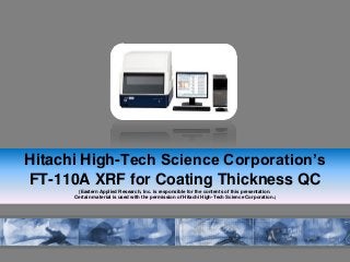
- 1. Hitachi High-Tech Science Corporation’s FT-110A XRF for Coating Thickness QC (Eastern Applied Research, Inc. is responsible for the contents of this presentation. Certain material is used with the permission of Hitachi High-Tech Science Corporation.)
- 2. Seiko Connection Hitachi High-Tech Science Corporation continues the Seiko Nano- Technologies XRF tradition, and Eastern Applied Research, Inc. is a distributor of Hitachi High-Tech Science Corporation products. High Precision Innovation Reliability Longevity
- 3. Building on Tradition Users of the Seiko SFT-3200 and SFT-9200 series will recognize many of the same benefits (and more) in the Hitachi FT-110A SFT-3200 SFT-9200 Hitachi FT-110A
- 4. FT110A Top Benefits 1. High Throughput, due to excellent autofocus option 2. Micro-Spot coating thickness measurements (electronics, etc) 3. Measure Up to 5 Layers with standards-less FP 4. Easy Positioning by unique wide view image option 5. Simplifies Testing of complex sample designs
- 5. Specifications Full Specifications: http://www.easternapplied.com/hitachi-FT110A-xrf-analyzer Measurement Direction Top-Down Measurable Elements Ti (22) – Bi (83) Atmosphere Air X-ray System Small, air cooled tube, W Target Tube Current Maximum 1000uA (variable) Primary Filter Automatic switching, on/off Detector Technology Proportional counter Collimator Size (beam size) 0.1 and 0.2 mm (options available) Maximum Sample Size 19.68” x 15.74” x 5.90” (W-D-H) Withstand Load 22lbs (10kg) Motorized XY Stage Drive 9.84x7.87” (optional movement) Repeatability +/- 5um Speed 1.57”/sec (40mm/sec)
- 6. Make It Your XRF Motorized XY Stage Fixed XY Stage Enclosed Chamber Slotted Chamber OR OR Collimator B 0.05, 0.1, 0.2 & 0.025x0.4mm X-ray Tube4 holes Collimator A 0.1 & 0.2mm X-ray Tube 2 holes OR
- 7. Make It Your XRF Narrow View Lens Wide View Lens Meas. Sample Dual Images Meas. Sample Narrow View LensSingle Image OR With Standard Samples Standard Free Method No NeedOR Auto Focus Laser PointerOR
- 8. Highlighted Features Auto-Focus Wide View Optics (Dual Image) Standard-less FP Method
- 9. X-ray tube CCD camera When the height within the measurement range differs, the camera automatically focuses, thus allowing rapid measuring. Distance measurement is done at the time of auto focus therefore measurement results are corrected in response to distance. Automatic Focus before focus after focus Auto-Focus Auto-Focus range is 3.14” (80mm) Time is within 3 seconds 70% reduction in time from conventional XRF
- 10. Focusing Click Click Does not focus when a sample is set Focusing Auto-Focus Automatic vertical drive of camera after distance measurement Z Range 5.9” X-ray box Camera axis range 3.14” X-ray Generator Table Plate Mirror X-rays Sample 1 X-ray box X-ray Generator X-rays Sample 2 Optic Axis Automatic downward drive of camera head after distance measurement Autofocus Function Auto Approach Function
- 11. Focal length Au (mm) Ni (mm) Au Error Ni Error Optimum 0.131 2.152 - - +10mm 0.128 2.188 2.67% 1.65% +20mm 0.126 2.199 3.82% 2.13% +40mm 0.126 2.191 3.82% 1.76% +60mm 0.132 2.127 0.76% 1.17% +80mm 0.138 2.054 4.96% 4.50% Effects of distance correction function on each focal point (Average of 20 repetitions) The error within 5% has been achieved for a standard distance within 80mm Auto-Focus
- 12. Why Add Wide-View Observation? Efficiency Wide View Save operator time and potential mistakes Streamline the process of sample positioning when measuring smaller points within a larger area (ie populated circuit board) Performance: Imaging Time: Max 20 seconds Resolution: 200mm Position Accuracy: ±2mm Digital Zoom: 0.2~5.7X Wide View Narrow View Sample
- 13. 7.87” 200mm 9.84” 250mm 0.20” 5.3mm 0.27” 7.1mm Wide field observation image Narrow field observation image First, acquire a wide field image of the entire sample stage. Then you select a narrow field image from the wide field image Wide View
- 14. Step 1: capture entire sample image Wide field image By capturing a maximum 9.84 x 7.87 ” sample image, multiple point measurements and positioning of large sample is made easy. Wide field image Step 2: expanded wide field image Scrolling the mouse easily expands the wide field images, such as for measurement locations Narrow field image Step 3: verify micro areas After moving the stage from the wide field image to the measurement location, set detailed positioning of microscopic area within the narrow field image. Wide View
- 15. As a result, a sensitivity coefficient must be obtained when creating conditions and by periodically measuring standard samples Proportional Counter detection systems are the most popular approach to maximize throughput for coating measurements. • Large peak overlap (separation is essential) • Effects of temperature change is large due to use of a gas However… Disadvantage of Prop-Count could be Combined spectrum of elements A and B F(x) = αf (x)+βg (x) F(x) αf (x) βg (x) Channel Film Analysis FP
- 16. NOW, the Hitachi FT-110A includes a newly developed separation process that combines with the characteristics of the proportional counter and enables measuring by a sensitivity coefficient registered beforehand. Improved performance by omitting prior operations In order to acquire a sensitivity coefficient before the Hitachi FT-110A…standards and time were required Film Analysis FP
- 17. Accuracy and reproducibility of 20 repetitions measuring Sn thin film Time 10 seconds 40 seconds Standards Sn: 1.01mm Average 1.08mm 1.09mm SD 0.027 0.011 Coef of Var 2.11% 1.01% Range 0.09mm 0.03mm Accuracy 6.4% 7.5% The newly improved Film Analysis FP method contributes to performance but cannot be employed if accuracy is not maintained Method Voltage Current Collimator Filter Film FP 50kV 625mA 0.1mm OFF Film Analysis FP
- 18. Application CV (%) 1st Layer Au (1.03um) 1.07 2nd Layer Ni (4.96um) 1.13 Base Cu 1st Layer Sn (4.83um) -3.7 Base Cu Examples of Standardless FP Applications Conditions: • 0.1mm Collimator • Primary Filter Off • Readings : 30 The Hitachi FT-110A offers newly developed thin film FP software that allows for standard-less analysis of up to ten (10) elements in a maximum of five (5) layers Standardless FP
- 19. Slotted Chamber enables measurement of large printed circuit boards up to 23.6” (W), 23.6” (D), 0.59” (H) Table Plate 27.5” (W) x 23.6” (D) Chamber Door Chassis Cover Slot 1.37” Slotted Chamber Standard, Enclosed, Design enables measurement of samples up to 19.6” (W), 15.7” (D), 5.9” (H). 0.66” 0.39” 0.31”
- 20. Example Configurations of the Hitachi FT-110A Configurations
- 21. Fixed XY Stage Laser Pointer Standard Free No Need + + X-ray Tube Collimator A 0.1 & 0.2mm Enclosed Chamber Meas. Sample Narrow View Lens Single Image + ++ Fastener Industry Zn/Fe Ni/Cu Ni/Brass Cu/Fe NiP/Fe NiP/Brass Bolts Nuts Screws Springs
- 22. ZnNi/Fe Zn/Fe Fixed XY Stage Auto Focus Standard Free No Need Meas. Sample Narrow View Lens Single Image ++ + Enclosed Chamber Collimator A 0.1 & 0.2mm ++ Automotive Parts
- 23. Al/Fe 10µm / Substrate 200µm / Substrate Cr/Fe 0.25µm / Substrate 25µm / Substrate Au/Ni [Cu] 0.05µm / Substrate 8µm / Substrate Ni/Cu 0.5µm / Substrate 30µm / Substrate Ag/Cu [Ni] 0.5µm / Substrate 70µm / Substrate Ni/CuZn 0.5µm / Substrate 30µm / Substrate Ag/Al 2µm / Substrate 70µm / Substrate Ni/CuSn 0.5µm / Substrate 30µm / Substrate Cd/Fe 1µm / Substrate 15µm / Substrate Ni/Fe 0.5µm / Substrate 40µm / Substrate Cu/Fe 1µm / Substrate 30µm / Substrate NiP/Cu 0.5µm / Substrate 30µm / Substrate Cu/CuZn 1µm / Substrate 30µm / Substrate NiP/CuZn 0.5µm / Substrate 30µm / Substrate Cu/Epoxy 1µm / Substrate 30µm / Substrate NiP/CuSn 0.5µm / Substrate 30µm / Substrate Single Layer Coating
- 24. Au/Ni/Cu Au/Ni/CuSn Au/Pd-Ni/Ni/CuSn Sn-Pb/Ni/CuSn Ag/Ni/CuSn Ag/Cu Meas. Sample Narrow View Lens Wide View Lens Dual ImagesMotorized XY Stage Laser Pointer With Standard Samples + + + Enclosed Chamber X-ray Tube Collimator B 0.05, 0.1, 0.2 & 0.025x0.4mm + + Electronics
- 25. Cr/Ni/Cu/Fe Cr/Ni/Cu/PLASTIC Ni/Cu/Fe Cu/Plastic Cu/Fe Au/Ni/PLASTIC Fixed XY Stage Auto Focus Meas. Sample Narrow View Lens Single Image + + X-ray Tube Collimator A 0.1 & 0.2mm Standard Free No Need Enclosed Chamber + + + Appliance Industry
- 26. SnPb/Ni/Cu SnPb/Cu Sn/Cu Au/Ni/Cu Slotted Chamber Auto FocusMotorized XY Stage With Standard Samples + + + Meas. Sample Narrow View Lens Wide View Lens Dual Images X-ray Tube Collimator B 0.05, 0.1, 0.2 & 0.025x0.4mm + + Printed Circuit Board
- 27. Au/Ni/Brass SnPb/Cu Ag/Cu Cu/Fe Ni/Cu/Fe Motorized XY Stage Laser Pointer With Standard Samples Collimator A 0.1 & 0.2mm Enclosed Chamber Meas. Sample Narrow View Lens Single Image + + +++ Small Electronics
- 28. Sn/Cu Sn/Cu/Fe Sn/Ni/Al Ag/Ni/Brass Ag/Ni/Al Enclosed Chamber Fixed XY Stage Meas. Sample Narrow View Lens Single Image Laser Pointer With Standard Samples Collimator A 0.1 & 0.2mm + + + + + Large Electronics
- 29. Au/Ni/Cu Au/Ni/Fe SnPb/CuSn SnPb/Ni/CuSn NiP/Fe Ni/Fe Enclosed Chamber Fixed XY Stage Meas. Sample Narrow View Lens Wide View Lens Dual Images Laser Pointer With Standard Samples Collimator B 0.05, 0.1, 0.2 & 0.025x0.4mm + + + + + Components
- 30. Au/Ni/Cu 0.05µm / 2µm / Substrate 3µm / 6µm / Substrate Au/Pd/Ni 0.05µm / 2µm / Substrate 3µm / 6µm / Substrate Ag/Ni/Cu 0.5µm / 2µm / Substrate 10µm / 6µm / Substrate Ag/Ni/CuSn 0.5µm / 2µm / Substrate 10µm / 6µm / Substrate Ni/Cu/Fe 0.5µm / 2µm / Substrate 20µm /20µm / Substrate Ni/Cu/Plastic 0.5µm / 2µm / Substrate 20µm /20µm / Substrate NiP/Cu/Fe 0.5µm / 2µm / Substrate 20µm /20µm / Substrate NiP/Cu/Zn 0.5µm / 2µm / Substrate 20µm /20µm / Substrate Multi-Layer Coatings
- 31. Cr/Ni/Cu/Plastic Enclosed Chamber Fixed XY Stage Meas. Sample Narrow View Lens Single Image Laser Pointer Standard Free No Need X-ray Tube Collimator A 0.1 & 0.2mm + + + + + Automotive Design
- 32. Au/Ni/CuZn Au/Pd/Ni/SnPb Au/Pt/Ni/SnPb Ag/Ni/Cu/SnPb Pt/Ni/CuZn Enclosed Chamber Fixed XY Stage Meas. Sample Narrow View Lens Single Image Laser Pointer With Standard Samples X-ray Tube Collimator A 0.1 & 0.2mm + + + + + Jewelry
- 33. SnPb/Cu 0.5µm / Substrate 30µm / Substrate SnPb/CuSn 0.5µm / Substrate 30µm / Substrate SnPb/Ni/CuSn 0.5µm / 2µm / Substrate 15µm / 5µm / Substrate ZnNi/Fe 5 µm / Substrate 15µm / Substrate SnZn/Fe 2 µm / Substrate 15µm / Substrate Alloy Coatings
- 34. Contact Info FT-110A Info and Literature: http://www.easternapplied.com/hitachi-FT110A-xrf-analyzer Contact Eastern Applied Research Inc for literature, demonstrations, discussions: http://www.easternapplied.com/ 716-201-1115 ~ sales@easternapplied.com