Residual stresses in inertia friction welded aeroengine materials
•
0 gefällt mir•511 views

ISIS Science Highlights. Residual stresses in inertia friction welded aeroengine materials.

Empfohlen
Weitere ähnliche Inhalte
Andere mochten auch
Andere mochten auch (13)
Mehr von ESS BILBAO
Mehr von ESS BILBAO (20)
Kürzlich hochgeladen
Kürzlich hochgeladen (20)
Residual stresses in inertia friction welded aeroengine materials
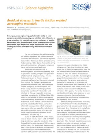
- 1. ISIS2003 Science Highlights Residual stresses in inertia friction welded aeroengine materials M Preuss, P J Withers (UMIST/University of Manchester), J W L Pang (Oak Ridge National Laboratory, USA) and GJ Baxter (Rolls-Royce plc) In many advanced engineering applications the ability to weld components reliably, reproducibly and with high joint efficiencies is a key technology. As materials improve, the challenges of welding become ever more demanding and, for the new generation of high performance, high temperature alloys, friction-based solid state welding techniques are fast becoming the industrial method of choice. The structural integrity of a weld is defined by the mechanical properties and the residual stresses Fig. 1: The full scale disc to disc inertia friction welder, based at the Rolls-Royce compressor rotor facility near apparent in the component. It is therefore important Derby, is expected to be implemented in the production to characterise the residual stresses generated during line in the year 2005. friction welding and the degree of stress relief during measurements were undertaken on the ENGIN post weld heat treatment before such a component diffractometer. With detectors placed at a given can be put into commercial application. angle, time of flight (TOF) measurements mean that Rolls-Royce has committed itself to the whole diffraction profile can be recorded as a establishing inertia and linear friction welding as its function of time. The presence of two detector major welding tools for joining the new generation banks, ±90° apart, means that the strains along two of advanced high temperature alloys. In inertia perpendicular sample directions can be measured friction welding, one of the work pieces is simultaneously. The sampling gauge volume is connected to a flywheel and the other is restrained defined by the intersection of the incident and from rotating. The flywheel is accelerated to a diffracted beams and the lattice parameter, a, of the predetermined rotational speed, then disengaged and the work pieces are forced together. The lattice planes with the plane normal parallel to the kinetic energy stored in the rotating flywheel is scattering vector, was determined by Rietveld dissipated as heat through friction at the weld refinement of the spectra. The residual strains were interface. In this way, it is possible to join new calculated by relating the lattice parameter of each nickel-base superalloys like RR1000 and Alloy 720LI, measurement point to the stress-free lattice which are not weldable by electron beam welding parameter of the parent material measured using (the current welding technique used by Rolls-Royce). the engineering strain equation. Furthermore, friction methods can form dissimilar When calculating strain and stress in this way, joints not possible by other means, such as two it is important to determine the stress-free lattice different Ni-base superalloys or high temperature parameter with a high accuracy (usually done in a far steel against nickel-base superalloy. Rolls-Royce is field region). Since the material of the heat affected planning to employ this process in the very near zone was exposed to high temperatures during future to join high pressure compressor drums, friction welding, each phase in a multiphase material turbine discs and shafts (fig. 1). can be expected to exhibit a chemical variation During an EPSRC/Royce-Rolls funded project, across the weld line (the element partitioning effect) residual stresses in inertia friction welds of RR1000 resulting in a variation of the stress-free lattice (high γ’ nickel-base superalloy, provided by Rolls- parameter. If this chemically related lattice parameter variation is not taken into account, significant Royce plc) with an outer diameter of 143 mm and a pseudo-strains/stresses are calculated leading to, in wall thickness 8 mm were studied. Measurements this case, an overestimation of the residual tensile were carried out for the as-welded, a conventional stresses close to the weld line. The characterisation and a modified post weld heat treated (PWHT) of the stress-free lattice parameter variation in the condition (50 °C above the conventional PWHT). All
- 2. ISIS2003 Science Highlights Residual stresses in inertia friction welded aeroengine materials (a) (b) (c) -2 1200 0 -1 0 70 800 60 0 00 40 400 600 10 R (mm) 30 0 80 0 40 1000 0 0 700 0 0 80 60 0 30 1 50 0 0 400 30 0 80 600 0 0 600 20 40 2 0 1 2 3 4 50 1 2 3 4 50 1 2 3 4 5 z (mm) 1400 1200 Fig. 2: Contour plots of the hoop stress fields (in MPa) in an inertia friction weld measured in the (a) as- 1000 welded, (b) conventional and (c) modified/new PWHT condition. Extremely large residual tensile stresses are 800 observed at the weld line (z = 0 mm) and close to the inner diameter of the tubular weld (R = -2.5) in the as- 600 welded condition. After conventional PWHT, the tensile stresses still reach 900 MPa, which is not acceptable 400 in a turbine disc component. Increasing the temperature of the PWHT by 50 °C reduces the tensile stresses 200 0 sufficiently below 500 MPa while maintaining an appropriate microstructure. heat affected zone is therefore an important part of The data collected on the ENGIN residual stress measurements. diffractometer indicate that the largest detrimental The change of stress-free lattice parameter was tensile stresses were generally observed in the hoop determined on thin slices cut from the weld using the direction, at the weld line and close to the inner biaxial sin2ψ method in conjunction with a collimated diameter. During friction welding, stresses were X-ray machine and the forced stress balance model. generated in the range of 1500 MPa (fig. 2a). The In order to calculate the residual stress fields in the conventional PWHT relieved the residual stresses welds, it is necessary to measure strain in the three only to a limited extent with tensile stresses in the principal directions (hoop, axial and radial) of the range of 1000 MPa at the weld line and close to the tubular weld. The lattice spacing was mapped out inner diameter (fig. 2b). Figure 2(c) shows that the over a plane at a specific hoop location between the modified PWHT was significantly more effective in weld line and up to 8 mm away from it. Due to the reducing the stresses to a maximum of about 400 relatively large neutron absorption coefficient of MPa. Together with metallurgical studies of the nickel, a neutron path length of 10 mm would reduce welds demonstrating that this PWHT does not the diffracted beam intensity by ≈80%. In order to compromise the microstructure and mechanical minimise the path length and facilitate the hoop properties of the material, a new PWHT for inertia strain measurements, a small window of 12x12 mm friction welded RR1000 has been suggested. was electro-discharge machined from the weld region of the welds at a position distant from the neutron measurement location. Contact: Dr M Preuss. Tel: +44 (0)161 200 3601. Email: michael.preuss@umist.ac.uk Further reading: M Preuss et al., Met. & Mat. Trans. 33, 3227 (2002). www.isis.rl.ac.uk