OCT Machines
•Als PPT, PDF herunterladen•
18 gefällt mir•5,439 views

OCT machines and their technical aspects

Empfohlen
Weitere ähnliche Inhalte
Was ist angesagt?
Was ist angesagt? (20)
Ähnlich wie OCT Machines
Ähnlich wie OCT Machines (20)
Mehr von Dr Samarth Mishra
Mehr von Dr Samarth Mishra (20)
Kürzlich hochgeladen
Kürzlich hochgeladen (20)
OCT Machines
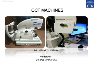
- 1. DR. SAMARTH MISHRA Moderator: DR. DEBMALYA DAS Nil financial interest OCT MACHINESOCT MACHINES
- 2. Principle of OCT machines TD- OCT in brief SD-OCT Spectralis OCT heidelberg SS-OCT in brief
- 3. What is Optical coherence tomography (OCT) ? “OCT represents a non invasive method for cross sectional imaging of the internal retinal structures, through the detection of optical reflections and echo time delays of light, using low coherence interferometry, to subsequently produce in vivo two dimensional images of internal tissue microstructure.” Optical Coherence Tomography: Newer Techniques, Newer Machines
- 4. • InterferometryInterferometry is a technique in which electromagnetic waves are superimposed causing the phenomenon of interference in order to extract information • In an interferometer, light from a single source is split into two beams that travel different optical paths, then combined again to produce interference. • The resulting interference fringes give information about the difference in optical path length. ‘Michelson interferometer’
- 5. Initially for in vivo measurements of axial length of eye by Fercher et al. (Medical University of Vienna, 1988) In early 90´s David Huang, a PhD student at MIT, on his research on low-coherence interferometry developed OCT. Cross-sectional tomographic imaging of retinal tissue. Uses backscattered light. Similar to ultrasound B-Scan imaging but uses infrared-light instead of ultrasound waves. Optical analog of ultrasound Fujimoto, James, and Eric Swanson. "The development, commercialization, and impact of optical coherence tomography." Investigative ophthalmology & visual science57.9 (2016): OCT1-OCT13.
- 6. Fujimoto, James, and Eric Swanson. "The development, commercialization, and impact of optical coherence tomography." Investigative ophthalmology & visual science57.9 (2016): OCT1-OCT13. First OCT protoype at MIT
- 7. Advantages:Advantages: Obtains high resolution images “Histological images” in vivo In real time Non-invasive Uses harmless radiation Ophthalmology, cardiology, odontology and dermatology
- 8. OCT TIMELINE
- 9. Fujimoto J, Swanson E. The development, commercialization, and impact of optical coherence tomography. Invest Ophthalmol Vis Sci. 2016;57:OCT1–OCT13. DOI:10.1167/ iovs.16-19963
- 10. Time domain ( TD-OCT) :Time domain ( TD-OCT) : • Stratus OCT, Carl zeiss meditech • Mobile reference arm mirror: allows backscattered tissue intensity levels to be detected from different depths in the tissue sample. • It is referred to as ‘time-domain’ because time-encoded signals are obtained directly. • 400 A scans/ sec • Axial resolution 10 um • lateral resolution 20um Longer acquisition time Motion artefacts Fujimoto, James, and Eric Swanson. "The development, commercialization, and impact of optical coherence tomography." Investigative ophthalmology & visual science57.9 (2016): OCT1-OCT13.
- 12. Spectral domain(SD-OCT) / Fourier domain OCT(FD-OCT) :Spectral domain(SD-OCT) / Fourier domain OCT(FD-OCT) : • Wavelength 800-850um • Stationary reference arm • High speed spectrometer • A charged couple device(CCD) line scan camera • Acquisition speed of 25k to 52k A scans/sec • Axial resolution 5-7microns. • lateral resolution 14-20microns.
- 14. ADVANTAGES: • Reduction of motion artefacts because of averaging. i.e multiple scans are acquired from the same position. • Better visualisation of individual retinal layers. • Improved signal to noise ratio
- 15. Description of Commercially Available SD-OCT Systems Device (Manufacturer) Description • 3D-OCT 2000 (Topcon,Tokyo, Japan) SD-OCT and high-resolution fundus camera; axial resolution 5um; A-scan acquisition rate 27 kHz. • Bioptigen SD-OCT (Bioptigen,NC) Designed for both clinical and research use and includes a hand-held probe and microscope setup; axial resolution 4um; A-scan acquisition rate 20 kHz • Cirrus HD-OCT (Carl Zeiss Meditec, Dublin, CA) Software includes guided progression analysis for glaucoma progression detection; axial resolution, 5um; A-scan acquisition rate 27 kHz. Gabriele, Michelle L., et al. "Optical coherence tomography: history, current status, and laboratory work." Investigative ophthalmology & visual science 52.5 (2011): 2425-
- 16. Device (Manufacturer) Description • RTVue-100 (Optovue, Fremont, CA) Offers multiple scanning protocols for glaucoma detection, including ganglion cell complex analysis; axial resolution 5um; A-scan acquisition rate 26 kHz. • SOCT Copernicus (Optopol, Zawiercie, Poland) Software includes progression analysis software that incorporates disk damage likelihood scale,asymmetry between the discs, and RNFL thickness; axial resolution, 6um; A-scan 27 kHz. • Spectral OCT SLO (Opko, Miami, FL) Combines SD-OCT, scanning laser ophthalmoscopy, and microperimetry. Axial resolution 6um, A-scan 27 kHz. Gabriele, Michelle L., et al. "Optical coherence tomography: history, current status, and laboratory work." Investigative ophthalmology & visual science 52.5 (2011): 2425-
- 17. Device (Manufacturer) Devices • Spectralis OCT (Heidelberg Engineering, Heidelberg, Germany) High-speed SD-OCT device with eye-eye- trackingtracking, fluorescein angiographyfluorescein angiography, ICGICG angiography, and autofluorescenceautofluorescence. Axial resolution,4um4um; A-scan acquisition rate 40 kHz40 kHz. Gabriele, Michelle L., et al. "Optical coherence tomography: history, current status, and laboratory work." Investigative ophthalmology & visual science 52.5 (2011): 2425- 2436.
- 18. Spectralis OCTSpectralis OCT ( Heidelberg Engineering , Germany )( Heidelberg Engineering , Germany ) • Dual beam SD-OCT and cSLO system. • Acquires volume scans of the retina and an infrared reference image simultaneously. • Eye tracker stablilizes the OCT scan • 40,000 A scans/sec
- 19. • Short examination timing • Simultaneous real time FFA/OCT and ICG/OCT. • Spectralis HRA+OCT is a combination of the Spectralis HRA and Spectralis OCT. • Allows angiography, reflectance imaging, autofluorescence imaging, and OCT cross sectional imaging, alone or in various combinations.
- 22. Confocal Laser ScanningConfocal Laser Scanning • For confocal images, a laser beam is focused on the retina. • SLO devices employ a confocal (pinhole) aperture, generating a single point of laser light, at a specific wavelength. • Can be scanned across the retina in a raster pattern. • As only a small area of the fundus is illuminated at any one time, the effects of light scatter are reduced and images with higher contrast are generated.
- 23. • Spectralis HRA emit laser light with three different wavelengths: 1. For excitation of fluorescein, a blue solid state laser (wavelength 488 nm) is used. A barrier filter at 500 nm separates excitation and fluorescence light. The same wavelength (but without the barrier filter) is used to create blue reflectance and autofluorescence images. Representations of confocal laser scanning microscopy to vi-sualize fluorescence staining and reflection properties of isolated reti-nal tissue. aA laser beam is conducted through a dichroic mirror andan objective to excite the fluorescent dye in the specimen. bTheemitted fluorescent light is conducted back through the objective anda dichroic mirror (worked as a light filter) to the light detector (e.g.photomultiplier). The pinhole enables the exclusive detection of lightcoming from a certain depth in the focused tissue area (confocality). cIn the reflection mode of the confocal laser scanning microscope, thelaser light for excitation is reflected from cellular structures in theretinal tissue, passes optical filters and is detected by thephotomultiplier. The pinhole is used to allow confocality
- 24. VIDEOVIDEO
- 25. 2. For excitation of indocyanine green, a diode laser at 790 nm wavelength is used, together with a barrier filter at 830 nm to separate excitation and fluorescence light. 3.A second diode laser at 820 nm wavelength serves to produce infrared reflectance (IR) images.
- 26. • SPECTRALIS® MultiColor Module incorporates a “multicolour” mode, where separate fundus images are obtained with blue, green, and near- infrared filters, and which can then be examined individually or in combination. • Shows distinct structures at different depths within the retina. • MultiColor images can highlight structures and pathologies not visible on ophthalmoscopy and fundus photography. CSCR MultiColor images may even be acquired in patients with cataract or nystagmus.
- 27. •Longer wavelengths of light penetrate more deeply – the use of near infrared filters thus greatly improves visualization of subretinal and choroidal structures (e.g. drusen subtypes in age-related macular degeneration (AMD)). •Shorter wavelengths of light (blue light), allow improved imaging of superficial retinal structures (e.g. retinal nerve fibre layer defects in glaucoma and epiretinal membranes).
- 28. •Intermediate wavelengths of light (green light (“red-free”)), provide optimal fundus images for general purposes. •Green wavelength is reflected by RPE, but absorbed by retinal haemorrhage and blood vessels.
- 29. • In the simultaneous imaging modes, each image line is scanned twice subsequently with alternating lasers. • So, during simultaneous FFA and ICGA, only the 488 nm laser is switched on for the first scan of a line, while during the second scan only the 790 nm laser is switched on.
- 30. Enhanced depth imaging ( EDI)Enhanced depth imaging ( EDI) • Spaide was the first to describe. • In standard OCT, the zero-delay line is typically at the vitreous inner retina junction, providing excellent resolution.
- 31. • The “zero-delay” line is a reference point set by the software where the image capture is optimal. • EDI is achieved by moving the zero delay line deeper into the eye, focusing the OCT scanner on the choroid instead of the retina. • Moving away from the zero-delay line decreases the resolution from structures within the choroid resulting in diminished choroidal detail.
- 32. Filter wheel position ‘R’ (Reflectance) How To Capture various modesHow To Capture various modes
- 33. Filter wheel position ‘A’ (Angiography)
- 34. Filter wheel position ‘P’ (Polarisation)
- 35. xyz-Micromanipulator For the adjustment of the camera position: • Inner knob: Z adjustment (forward/backward) • Middle knob: Y adjustment (height) • outer knob: x adjustment (left/right) X Y Z
- 36. Scanning techniques:Scanning techniques: • The commonly used scan protocols for macular scanning are three dimensional (3D)scan, radial scan, and raster scan.‑ • A 3D scan consists of a number of horizontal line scans composing a 6 mm × 6 mm/ 7 mm × 7 mm / 12 mm× 9 mm rectangular box. • A minimum pupil diameter of 3 mm is required to obtain a good OCT image.
- 37. Types of Radial ScansTypes of Radial Scans 30°30° 4 Lines, 45°4 Lines, 45° 6 Lines, 30°6 Lines, 30° 12 Lines, 15°12 Lines, 15° 24 Lines, 7.5°24 Lines, 7.5° 48 Lines, 3.8°48 Lines, 3.8° 2 Lines, 90°2 Lines, 90°
- 38. Types of Raster ScansTypes of Raster Scans Single line scanSingle line scan Detail Scan, 30umDetail Scan, 30um 7 line scan, 240um7 line scan, 240um Fast scan , 240umFast scan , 240um Dense Scan, 120umDense Scan, 120um
- 39. • Thickness map displays the average retinal thickness values in 1 mm, 3 mm, and 6 mm diameter circles. • Divided into sectors with color map. • Warm colors indicate thicker retinal areas and cool color indicate thinner retinal areas
- 40. • The SPECTRALIS® Widefield Imaging Module provides a 55-degree field of view for all fundus imaging modalities including MultiColor, BluePeak, IR, angiography, and OCT. • The Widefield Imaging Module facilitates comprehensive diagnostics. • The high-resolution, high-contrast scanning laser images captured with the Widefield Imaging Module offer diagnostic capabilities beyond those of conventional fundus photography. The optional Ultra-Widefield Angiography Module (102 °) delivers scanning laser angiography images from the macula to the periphery for more comprehensive retinal examinations.
- 41. Changing lenses for ImagingChanging lenses for Imaging • To remove the objective lens , it is rotated by 50° to the left (counter clockwise). 30°Objective lens
- 42. • The optional 55°wide angle lens • For IR, RF and angiography wide-field imaging • Has to be inserted with the red dot orientated upwards (12 o’clock) • Then rotated by about 50°clockwise until it snaps in. 55°wide angle lens
- 43. Step 1 Step 2 Step 3 102°Ultra wide field lens
- 44. FOCUS KNOB: • By turning this knob, refractive errors of the patient’s eye can be compensated. • For examination of most patients, an initial focus setting of ‘0’ (zero diopters) is suitable.
- 46. • Also called Optical Frequency Domain OCT • Obtains time-encoded information by sweeping a narrow bandwidth laser through a broad optical spectrum • Backscattered intensity is detected with a photodetector. • This process is in contrast to SD-OCT, which uses a broad bandwidth light source and detects the interference spectra with a CCD camera and spectrometer. First high speed OFDI system: S.H. Yun et al, Opt. Express 11, 2953-2963 (2003) Swept source oct
- 47. • Speeds of up to 249,000A-scans/s have been attained • Eye motion artifacts are greatly reduced compared with TD-OCT. • A drawback to camera-based SD-OCT detection is a drop-off in signal with depth of scanning because of the finite pixel size of the CCD camera. Taken from “Swept-Source Optical Coherence Tomography” presentation by Dr Muna Bhende
- 48. • Wide 12 mm scans – evaluation of disc- macula relationships in one frame Taken from “Swept-Source Optical Coherence Tomography” presentation by Dr Muna Bhende
- 49. 12 mm 12 mm 12 mm Taken from “Swept-Source Optical Coherence Tomography” presentation by Dr Muna Bhende 36 mm !!
- 50. Comparison of TD-, SD-, and SS-OCT DevicesComparison of TD-, SD-, and SS-OCT Devices
- 51. •Employs motion contrast imaging to high-resolution volumetric blood flow information generating angiographic images. •Compares the ‘decorrelation signal’‘decorrelation signal’ between sequential OCT B-Scans taken at precisely the same cross section in order to construct a map of blood flow. Other OCT systems:Other OCT systems: Optical coherence tomography angiography (OCTA)Optical coherence tomography angiography (OCTA) En face OCT:En face OCT: •Derived from SD OCT. Produces frontal sections of retinal layers, also called ‘C-scan OCT’.
- 52. Adaptive optics OCTAdaptive optics OCT • Corrects for higher-order ocular aberrations Doppler OCTDoppler OCT • measuring the Doppler shift and relative angle between the OCT beam and a blood vessel, assess the blood flow velocity. Polarization sensitive OCTPolarization sensitive OCT • used for functional tissue assessment by means of evaluation of light polarization which allows individual retinal layer identification Image taken from “Swept-Source Optical Coherence Tomography” presentation by Dr Muna Bhende
- 53. OCT is a quick, non invasive and harmless examination technique Can be used to rapidly access the pathologies of retina and choroid Better and improved machines with better resolution. Future of OCT with newer advances is even more promising. OCT is here to stay !!OCT is here to stay !! To summarizeTo summarize
- 54. THANK YOU
- 56. • Automated segmentation into the “superficial” and “deep” inner retinal vascular plexuses, outer retina, and choriocapillaris • The OCT angiogram segmentation of the superficial inner retina contains a projection of the vasculature in the retinal nerve fiber layer (RNFL) and ganglion cell layer (GCL) Superficial capillary plexusSuperficial capillary plexus Deep capillary plexusDeep capillary plexus
- 57. • The deep inner retina OCT angiogram shows a composite of the vascular plexuses at the border of the IPL/INL and the border of the INL/ OPL. Deep capillary plexusDeep capillary plexus choriocapillarieschoriocapillaries
- 58. Sattler’s layerSattler’s layer Haller’s layerHaller’s layer