SlideShare ist ein Scribd-Unternehmen logo
1 von 9
Diode as switch:
Electrical Switches over Mechanical Switches
Electrical switches are a preferred choice over mechanical switches due to the following
reasons −
 Mechanical switches are prone to oxidation of metals whereas electrical switches
don’t.
 Mechanical switches have movable contacts.
 They are more prone to stress and strain than electrical switches.
 The worn and torn of mechanical switches often affect their working.
Hence an electrical switch is more useful than a Mechanical switch.
Working of Diode as a Switch
Whenever a specified voltage is exceeded, the diode resistance gets increased, making
the diode reverse biased and it acts as an open switch. Whenever the voltage applied is
below the reference voltage, the diode resistance gets decreased, making the diode
forward biased, and it acts as a closed switch.
The following circuit explains the diode acting as a switch.
A switching diode has a PN junction in which P-region is lightly doped and N-region is
heavily doped. The above circuit symbolizes that the diode gets ON when positive
voltage forward biases the diode and it gets OFF when negative voltage reverse biases
the diode.
Ringing
As the forward current flows till then, with a sudden reverse voltage, the reverse current
flows for an instance rather than getting switched OFF immediately. The higher the
leakage current, the greater the loss. The flow of reverse current when diode is reverse
biased suddenly, may sometimes create few oscillations, called as RINGING.
This ringing condition is a loss and hence should be minimized. To do this, the switching
times of the diode should be understood.
Diode Switching Times
While changing the bias conditions, the diode undergoes a transient response. The
response of a system to any sudden change from an equilibrium position is called as
transient response.
The sudden change from forward to reverse and from reverse to forward bias, affects
the circuit. The time taken to respond to such sudden changes is the important criterion
to define the effectiveness of an electrical switch.
 The time taken before the diode recovers its steady state is called as Recovery
Time.
 The time interval taken by the diode to switch from reverse biased state to
forward biased state is called as Forward Recovery Time.$tfr$$tfr$
 The time interval taken by the diode to switch from forward biased state to
reverse biased state is called as Reverse Recovery Time. $tfr$$tfr$
To understand this more clearly, let us try to analyze what happens once the voltage is
applied to a switching PN diode.
The main application of p-n junction diode is in rectification circuits. These circuits are used to
describe the conversion of a.c signals to d.c in power supplies. Diode rectifier gives an alternating
voltage which pulsates in accordance with time. The filter smoothes the pulsation in the voltage and
to produce d.c voltage, a regulator is used which removes the ripples.
There are two primary methods of diode rectification:
 Half Wave Rectifier
 Full Wave Rectifier
Table of Contents
 Half Wave Rectifier
 Working of Half Wave Rectifier
 Characteristics of Half Wave Rectifier
 Advantages of Half Wave Rectifier
 Disadvantages of Half Wave Rectifier
 Applications of Half Wave Rectifier
 Full Wave Rectifier
 Working of Full Wave Rectifier
 Characteristics of Full Wave Rectifier
 Types of Full Wave Rectifier
 Advantages of Full Wave Rectifier
 Disadvantages of Full Wave Rectifier
 Applications of Full Wave Rectifier
 Difference
What is Half Wave Rectifier?
In a half-wave rectifier, one half of each a.c input cycle is rectified. When the p-n junction diode is
forward biased, it gives little resistance and when it is reversed biased it provides high resistance.
During one-half cycles, the diode is forward biased when the input voltage is applied and in the
opposite half cycle, it is reverse biased. During alternate half-cycles, the optimum result can be
obtained.
Working of Half Wave Rectifier
The half-wave rectifier has both positive and negative cycles. During the positive half of the input,
the current will flow from positive to negative which will generate only a positive half cycle of the a.c
supply. When a.c supply is applied to the transformer, the voltage will be decreasing at the
secondary winding of the diode. All the variations in the a.c supply will reduce, and we will get the
pulsating d.c voltage to the load resistor.
In the second half cycle, the current will flow from negative to positive and the diode will be reverse
biased. Thus, at the output side, there will be no current generated, and we cannot get power at the
load resistance. A small amount of reverse current will flow during reverse bias due to minority
carriers.
Characteristics of Half Wave Rectifier
Following are the characteristics of half-wave rectifier:
Ripple Factor
Ripples are the oscillations that are obtained in DC which are corrected by using filters such as
inductors and capacitors. These ripples are measured with the help of the ripple factor and are
denoted by γ. Ripple factor tells us the number of ripples presents in the output DC. Higher the ripple
factor, more is the oscillation at the output DC and lower is the ripple factor, less is the oscillation at
the output DC.
Ripple factor is the ratio of RMS value of the AC component of the output voltage to the DC
component of the output voltage.
γ=(VrmsVDC)2−1
DC Current
DC current is given as:
IDC=Imaxπ
Where,
 Imax is the maximum DC load current
DC Output Voltage
The output DC voltage appears at the load resistor RL which is obtained by multiplying output DC
voltage with the load resistor RL. The output DC voltage is given as:
VDC=VSmaxπ
Where,
 VSmax is the maximum secondary voltage
Form Factor
The form factor is the ratio of RMS value to the DC value. For a half-wave rectifier, the form factor
is 1.57.
Rectifier Efficiency
Rectifier efficiency is the ratio of output DC power to the input AC power. For a half-wave rectifier,
rectifier efficiency is 40.6%.
Advantages of Half Wave Rectifier
 Affordable
 Simple connections
 Easy to use as the connections are simple
 Number of components used are less
Disadvantages of Half Wave Rectifier
 Ripple production is more
 Harmonics are generated
 Utilization of the transformer is very low
 The efficiency of rectification is low
Applications of Half Wave Rectifier
Following are the uses of half-wave rectification:
 Power rectification: Half wave rectifier is used along with a transformer for power
rectification as powering equipment.
 Signal demodulation: Half wave rectifiers are used for demodulating the AM signals.
 Signal peak detector: Half wave rectifier is used for detecting the peak of the incoming
waveform.
What is Full Wave Rectifier?
Full-wave rectifier circuits are used for producing an output voltage or output current which is purely
DC. The main advantage of a full-wave rectifier over half-wave rectifier is that such as the average
output voltage is higher in full-wave rectifier, there is less ripple produced in full-wave rectifier when
compared to the half-wave rectifier.
Working of Full Wave Rectifier
The full-wave rectifier utilizes both halves of each a.c input. When the p-n junction is forward biased,
the diode offers low resistance and when it is reverse biased it gives high resistance. The circuit is
designed in such a manner that in the first half cycle if the diode is forward biased then in the second
half cycle it is reverse biased and so on.
Characteristics of Full Wave Rectifier
Following are the characteristics of full-wave rectifier:
Ripple Factor
Ripple factor for a full-wave rectifier is given as:
γ=(VrmsVDC)2−1
DC Current
Currents from both the diodes D1 and D2 are in the same direction when they flow towards load
resistor RL. The current produced by both the diodes is the ratio of Imax to π, therefore the DC current
is given as:
IDC=2Imaxπ
Where,
 Imax is the maximum DC load current
DC Output Voltage
DC output voltage is obtained at the load resistor RL and is given as:
VDC=2Vmaxπ
Where,
 Vmax is the maximum secondary voltage
Form Factor
The form factor is the ratio of RMS value of current to the output DC voltage. The form factor of a
full-wave rectifier is given as 1.11
Rectifier Efficiency
Rectifier efficiency is used as a parameter to determine the efficiency of the rectifier to convert AC
into DC. It is the ratio of DC output power to the AC input power. The rectifier efficiency of a full-
wave rectifier is 81.2%.
Types of Full Wave Rectifier
There are two main types of full-wave rectifiers, and they are:
 Two diodes full-wave rectifier circuit (requires a center-tapped transformer and is used in
vacuum tubes)
 Bridge rectifier circuit (doesn’t require a centre-tapped transformer and is used along with
transformers for efficient usage)
Advantages of Full Wave Rectifier
 The rectifier efficiency of a full-wave rectifier is high
 The power loss is very low
 Number of ripples generated are less
Disadvantages of Full Wave Rectifier
 Very expensive
Applications of Full Wave Rectifier
Following are the uses of full-wave rectifier:
 Full-wave rectifiers are used for supplying polarized voltage in welding and for this bridge
rectifiers are used.
 Full-wave rectifiers are used for detecting the amplitude of modulated radio signals.
Difference between Half Wave Rectifier and Full Wave Rectifier
Parameter Half Wave Rectifier Full Wave Rectifier
Definition
The half-wave rectifier is
a rectifier which is used
for converting the one-
half cycle of AC input to
DC output
A full-wave rectifier is a
rectifier which is used for
converting both the half
cycles of AC input into
DC output
No. of diodes used 1
2 or 4 depending on the
type of circuit
Form factor 1.57 1.11
Rectifier efficiency 40.6% 81.2%
Ripple factor
Ripple factor of a half-
wave rectifier is more
Ripple factor of a full-
wave rectifier is less
Frequently Asked Questions – FAQs
Why half-wave rectifiers are not used in dc power supply?
Half-wave rectifiers are not used in dc power supply because the supply provided by the half-wave
rectifier is not satisfactory.
What is PIV of a diode in a rectifier circuit?
PIV stands for peak inverse voltage and it is the maximum voltage that is possible to occur across
the diode when it is operated in reverse biased.
What is a ripple in a rectifier circuit?
Ripple is defined as the ac component that has a pulsating output in a rectifier.
What are the advantages of a bridge rectifier over a center-tapped full-wave
rectifier?
Following are the three advantages of bridge rectifier over a center-tapped full-wave rectifier:
 The TUF of a bridge rectifier is 81.2% while the TUF of a center-tapped is 67.2%.
 The output of the bridge rectifier is twice that of the center-tapped full-wave rectifier.
 A bridge rectifier as a PIV half of the center-tapped full-wave rectifier.
What is the cycle followed by the current in a full-wave rectifier?
In a full-wave rectifier, the current flows in the half cycle of the input signal.
What happens to the peak current if the value of the shunt capacitor filter is
increased?
When the value of the shunt capacitor filter is increased, the peak current will also increase in a
rectifying diode.
Why bridge rectifier is preferred over an ordinary two diodes full-wave
rectifier?
A bridge rectifier is preferred over an ordinary two diodes full-wave rectifier because:
 The PIV is less per diode
 There is no need for the centre tap
Electrical Switches over Mechanical Switches.docx

Weitere ähnliche Inhalte

Ähnlich wie Electrical Switches over Mechanical Switches.docx

Full wave rectifier.pptx
Full wave rectifier.pptxFull wave rectifier.pptx
Full wave rectifier.pptxAbidKhanNishat1
 
Halfwave and full wave rectificaton
Halfwave and full wave rectificaton Halfwave and full wave rectificaton
Halfwave and full wave rectificaton University of Karachi
 
POWER SUPPLY(Ashu).pptx
POWER SUPPLY(Ashu).pptxPOWER SUPPLY(Ashu).pptx
POWER SUPPLY(Ashu).pptxAshu Chaudhary
 
Full Wave Rectifier Circuit Working and Theory
Full Wave Rectifier Circuit Working and TheoryFull Wave Rectifier Circuit Working and Theory
Full Wave Rectifier Circuit Working and Theoryelprocus
 
377275109-Ch-2-Uncontrolled-Rectifiers-Autosaved.pptx
377275109-Ch-2-Uncontrolled-Rectifiers-Autosaved.pptx377275109-Ch-2-Uncontrolled-Rectifiers-Autosaved.pptx
377275109-Ch-2-Uncontrolled-Rectifiers-Autosaved.pptxpriyakunduq
 
ECE 505 Power electronics final paper
ECE 505 Power electronics final paperECE 505 Power electronics final paper
ECE 505 Power electronics final paperRob Garrone
 
Power electronics Uncontrolled Rectifiers - Diode Rectifiers
Power electronics   Uncontrolled Rectifiers - Diode RectifiersPower electronics   Uncontrolled Rectifiers - Diode Rectifiers
Power electronics Uncontrolled Rectifiers - Diode RectifiersBurdwan University
 
Full Wave Rectifier (FWR) Microproject
Full Wave Rectifier (FWR) MicroprojectFull Wave Rectifier (FWR) Microproject
Full Wave Rectifier (FWR) MicroprojectOmprakash Chauhan
 
Full Wave Rectifier(SI diode)
Full Wave Rectifier(SI diode)Full Wave Rectifier(SI diode)
Full Wave Rectifier(SI diode)SyedFahim20
 
Full wave rectifier (Si Diode)
Full wave rectifier (Si Diode)Full wave rectifier (Si Diode)
Full wave rectifier (Si Diode)SyedFahimShahriar
 
Bshajsjssjsbsbshshsjsjsjdnsnsndndndnsbdbddhdhdhdhdhdhddjdjdjdjdhdndjdhdhdhd.pptx
Bshajsjssjsbsbshshsjsjsjdnsnsndndndnsbdbddhdhdhdhdhdhddjdjdjdjdhdndjdhdhdhd.pptxBshajsjssjsbsbshshsjsjsjdnsnsndndndnsbdbddhdhdhdhdhdhddjdjdjdjdhdndjdhdhdhd.pptx
Bshajsjssjsbsbshshsjsjsjdnsnsndndndnsbdbddhdhdhdhdhdhddjdjdjdjdhdndjdhdhdhd.pptxdevanarayanobx1b
 
Basic of Diode Rectifiers
Basic of Diode RectifiersBasic of Diode Rectifiers
Basic of Diode Rectifiersssuser4b487e1
 
Rectifiers and Filter Circuits
Rectifiers and Filter CircuitsRectifiers and Filter Circuits
Rectifiers and Filter CircuitsRakesh Sheoran
 
Unit-III Electronics.pdf
Unit-III Electronics.pdfUnit-III Electronics.pdf
Unit-III Electronics.pdfSachinNaagar4
 

Ähnlich wie Electrical Switches over Mechanical Switches.docx (20)

Chapter 1.
Chapter 1.Chapter 1.
Chapter 1.
 
Full wave rectifier.pptx
Full wave rectifier.pptxFull wave rectifier.pptx
Full wave rectifier.pptx
 
Halfwave and full wave rectificaton
Halfwave and full wave rectificaton Halfwave and full wave rectificaton
Halfwave and full wave rectificaton
 
Lec-3.pdf
Lec-3.pdfLec-3.pdf
Lec-3.pdf
 
POWER SUPPLY(Ashu).pptx
POWER SUPPLY(Ashu).pptxPOWER SUPPLY(Ashu).pptx
POWER SUPPLY(Ashu).pptx
 
Full Wave Rectifier Circuit Working and Theory
Full Wave Rectifier Circuit Working and TheoryFull Wave Rectifier Circuit Working and Theory
Full Wave Rectifier Circuit Working and Theory
 
377275109-Ch-2-Uncontrolled-Rectifiers-Autosaved.pptx
377275109-Ch-2-Uncontrolled-Rectifiers-Autosaved.pptx377275109-Ch-2-Uncontrolled-Rectifiers-Autosaved.pptx
377275109-Ch-2-Uncontrolled-Rectifiers-Autosaved.pptx
 
Rectifier
RectifierRectifier
Rectifier
 
ECE 505 Power electronics final paper
ECE 505 Power electronics final paperECE 505 Power electronics final paper
ECE 505 Power electronics final paper
 
Half wave rectifier
Half wave rectifierHalf wave rectifier
Half wave rectifier
 
Power electronics Uncontrolled Rectifiers - Diode Rectifiers
Power electronics   Uncontrolled Rectifiers - Diode RectifiersPower electronics   Uncontrolled Rectifiers - Diode Rectifiers
Power electronics Uncontrolled Rectifiers - Diode Rectifiers
 
task_2.pptx
task_2.pptxtask_2.pptx
task_2.pptx
 
Full Wave Rectifier (FWR) Microproject
Full Wave Rectifier (FWR) MicroprojectFull Wave Rectifier (FWR) Microproject
Full Wave Rectifier (FWR) Microproject
 
Full Wave Rectifier(SI diode)
Full Wave Rectifier(SI diode)Full Wave Rectifier(SI diode)
Full Wave Rectifier(SI diode)
 
Full wave rectifier (Si Diode)
Full wave rectifier (Si Diode)Full wave rectifier (Si Diode)
Full wave rectifier (Si Diode)
 
Bshajsjssjsbsbshshsjsjsjdnsnsndndndnsbdbddhdhdhdhdhdhddjdjdjdjdhdndjdhdhdhd.pptx
Bshajsjssjsbsbshshsjsjsjdnsnsndndndnsbdbddhdhdhdhdhdhddjdjdjdjdhdndjdhdhdhd.pptxBshajsjssjsbsbshshsjsjsjdnsnsndndndnsbdbddhdhdhdhdhdhddjdjdjdjdhdndjdhdhdhd.pptx
Bshajsjssjsbsbshshsjsjsjdnsnsndndndnsbdbddhdhdhdhdhdhddjdjdjdjdhdndjdhdhdhd.pptx
 
Basic of Diode Rectifiers
Basic of Diode RectifiersBasic of Diode Rectifiers
Basic of Diode Rectifiers
 
Rectifiers and Filter Circuits
Rectifiers and Filter CircuitsRectifiers and Filter Circuits
Rectifiers and Filter Circuits
 
Unit-III Electronics.pdf
Unit-III Electronics.pdfUnit-III Electronics.pdf
Unit-III Electronics.pdf
 
Eg1108 rectifiers
Eg1108 rectifiersEg1108 rectifiers
Eg1108 rectifiers
 

Kürzlich hochgeladen

Magic bus Group work1and 2 (Team 3).pptx
Magic bus Group work1and 2 (Team 3).pptxMagic bus Group work1and 2 (Team 3).pptx
Magic bus Group work1and 2 (Team 3).pptxdhanalakshmis0310
 
PROCESS RECORDING FORMAT.docx
PROCESS      RECORDING        FORMAT.docxPROCESS      RECORDING        FORMAT.docx
PROCESS RECORDING FORMAT.docxPoojaSen20
 
microwave assisted reaction. General introduction
microwave assisted reaction. General introductionmicrowave assisted reaction. General introduction
microwave assisted reaction. General introductionMaksud Ahmed
 
ComPTIA Overview | Comptia Security+ Book SY0-701
ComPTIA Overview | Comptia Security+ Book SY0-701ComPTIA Overview | Comptia Security+ Book SY0-701
ComPTIA Overview | Comptia Security+ Book SY0-701bronxfugly43
 
ICT Role in 21st Century Education & its Challenges.pptx
ICT Role in 21st Century Education & its Challenges.pptxICT Role in 21st Century Education & its Challenges.pptx
ICT Role in 21st Century Education & its Challenges.pptxAreebaZafar22
 
SKILL OF INTRODUCING THE LESSON MICRO SKILLS.pptx
SKILL OF INTRODUCING THE LESSON MICRO SKILLS.pptxSKILL OF INTRODUCING THE LESSON MICRO SKILLS.pptx
SKILL OF INTRODUCING THE LESSON MICRO SKILLS.pptxAmanpreet Kaur
 
Kodo Millet PPT made by Ghanshyam bairwa college of Agriculture kumher bhara...
Kodo Millet  PPT made by Ghanshyam bairwa college of Agriculture kumher bhara...Kodo Millet  PPT made by Ghanshyam bairwa college of Agriculture kumher bhara...
Kodo Millet PPT made by Ghanshyam bairwa college of Agriculture kumher bhara...pradhanghanshyam7136
 
Micro-Scholarship, What it is, How can it help me.pdf
Micro-Scholarship, What it is, How can it help me.pdfMicro-Scholarship, What it is, How can it help me.pdf
Micro-Scholarship, What it is, How can it help me.pdfPoh-Sun Goh
 
The basics of sentences session 3pptx.pptx
The basics of sentences session 3pptx.pptxThe basics of sentences session 3pptx.pptx
The basics of sentences session 3pptx.pptxheathfieldcps1
 
Basic Civil Engineering first year Notes- Chapter 4 Building.pptx
Basic Civil Engineering first year Notes- Chapter 4 Building.pptxBasic Civil Engineering first year Notes- Chapter 4 Building.pptx
Basic Civil Engineering first year Notes- Chapter 4 Building.pptxDenish Jangid
 
Unit-V; Pricing (Pharma Marketing Management).pptx
Unit-V; Pricing (Pharma Marketing Management).pptxUnit-V; Pricing (Pharma Marketing Management).pptx
Unit-V; Pricing (Pharma Marketing Management).pptxVishalSingh1417
 
Key note speaker Neum_Admir Softic_ENG.pdf
Key note speaker Neum_Admir Softic_ENG.pdfKey note speaker Neum_Admir Softic_ENG.pdf
Key note speaker Neum_Admir Softic_ENG.pdfAdmir Softic
 
Seal of Good Local Governance (SGLG) 2024Final.pptx
Seal of Good Local Governance (SGLG) 2024Final.pptxSeal of Good Local Governance (SGLG) 2024Final.pptx
Seal of Good Local Governance (SGLG) 2024Final.pptxnegromaestrong
 
UGC NET Paper 1 Mathematical Reasoning & Aptitude.pdf
UGC NET Paper 1 Mathematical Reasoning & Aptitude.pdfUGC NET Paper 1 Mathematical Reasoning & Aptitude.pdf
UGC NET Paper 1 Mathematical Reasoning & Aptitude.pdfNirmal Dwivedi
 
How to Manage Global Discount in Odoo 17 POS
How to Manage Global Discount in Odoo 17 POSHow to Manage Global Discount in Odoo 17 POS
How to Manage Global Discount in Odoo 17 POSCeline George
 
1029-Danh muc Sach Giao Khoa khoi 6.pdf
1029-Danh muc Sach Giao Khoa khoi  6.pdf1029-Danh muc Sach Giao Khoa khoi  6.pdf
1029-Danh muc Sach Giao Khoa khoi 6.pdfQucHHunhnh
 
1029 - Danh muc Sach Giao Khoa 10 . pdf
1029 -  Danh muc Sach Giao Khoa 10 . pdf1029 -  Danh muc Sach Giao Khoa 10 . pdf
1029 - Danh muc Sach Giao Khoa 10 . pdfQucHHunhnh
 
Russian Escort Service in Delhi 11k Hotel Foreigner Russian Call Girls in Delhi
Russian Escort Service in Delhi 11k Hotel Foreigner Russian Call Girls in DelhiRussian Escort Service in Delhi 11k Hotel Foreigner Russian Call Girls in Delhi
Russian Escort Service in Delhi 11k Hotel Foreigner Russian Call Girls in Delhikauryashika82
 
TỔNG ÔN TẬP THI VÀO LỚP 10 MÔN TIẾNG ANH NĂM HỌC 2023 - 2024 CÓ ĐÁP ÁN (NGỮ Â...
TỔNG ÔN TẬP THI VÀO LỚP 10 MÔN TIẾNG ANH NĂM HỌC 2023 - 2024 CÓ ĐÁP ÁN (NGỮ Â...TỔNG ÔN TẬP THI VÀO LỚP 10 MÔN TIẾNG ANH NĂM HỌC 2023 - 2024 CÓ ĐÁP ÁN (NGỮ Â...
TỔNG ÔN TẬP THI VÀO LỚP 10 MÔN TIẾNG ANH NĂM HỌC 2023 - 2024 CÓ ĐÁP ÁN (NGỮ Â...Nguyen Thanh Tu Collection
 
Unit-IV- Pharma. Marketing Channels.pptx
Unit-IV- Pharma. Marketing Channels.pptxUnit-IV- Pharma. Marketing Channels.pptx
Unit-IV- Pharma. Marketing Channels.pptxVishalSingh1417
 

Kürzlich hochgeladen (20)

Magic bus Group work1and 2 (Team 3).pptx
Magic bus Group work1and 2 (Team 3).pptxMagic bus Group work1and 2 (Team 3).pptx
Magic bus Group work1and 2 (Team 3).pptx
 
PROCESS RECORDING FORMAT.docx
PROCESS      RECORDING        FORMAT.docxPROCESS      RECORDING        FORMAT.docx
PROCESS RECORDING FORMAT.docx
 
microwave assisted reaction. General introduction
microwave assisted reaction. General introductionmicrowave assisted reaction. General introduction
microwave assisted reaction. General introduction
 
ComPTIA Overview | Comptia Security+ Book SY0-701
ComPTIA Overview | Comptia Security+ Book SY0-701ComPTIA Overview | Comptia Security+ Book SY0-701
ComPTIA Overview | Comptia Security+ Book SY0-701
 
ICT Role in 21st Century Education & its Challenges.pptx
ICT Role in 21st Century Education & its Challenges.pptxICT Role in 21st Century Education & its Challenges.pptx
ICT Role in 21st Century Education & its Challenges.pptx
 
SKILL OF INTRODUCING THE LESSON MICRO SKILLS.pptx
SKILL OF INTRODUCING THE LESSON MICRO SKILLS.pptxSKILL OF INTRODUCING THE LESSON MICRO SKILLS.pptx
SKILL OF INTRODUCING THE LESSON MICRO SKILLS.pptx
 
Kodo Millet PPT made by Ghanshyam bairwa college of Agriculture kumher bhara...
Kodo Millet  PPT made by Ghanshyam bairwa college of Agriculture kumher bhara...Kodo Millet  PPT made by Ghanshyam bairwa college of Agriculture kumher bhara...
Kodo Millet PPT made by Ghanshyam bairwa college of Agriculture kumher bhara...
 
Micro-Scholarship, What it is, How can it help me.pdf
Micro-Scholarship, What it is, How can it help me.pdfMicro-Scholarship, What it is, How can it help me.pdf
Micro-Scholarship, What it is, How can it help me.pdf
 
The basics of sentences session 3pptx.pptx
The basics of sentences session 3pptx.pptxThe basics of sentences session 3pptx.pptx
The basics of sentences session 3pptx.pptx
 
Basic Civil Engineering first year Notes- Chapter 4 Building.pptx
Basic Civil Engineering first year Notes- Chapter 4 Building.pptxBasic Civil Engineering first year Notes- Chapter 4 Building.pptx
Basic Civil Engineering first year Notes- Chapter 4 Building.pptx
 
Unit-V; Pricing (Pharma Marketing Management).pptx
Unit-V; Pricing (Pharma Marketing Management).pptxUnit-V; Pricing (Pharma Marketing Management).pptx
Unit-V; Pricing (Pharma Marketing Management).pptx
 
Key note speaker Neum_Admir Softic_ENG.pdf
Key note speaker Neum_Admir Softic_ENG.pdfKey note speaker Neum_Admir Softic_ENG.pdf
Key note speaker Neum_Admir Softic_ENG.pdf
 
Seal of Good Local Governance (SGLG) 2024Final.pptx
Seal of Good Local Governance (SGLG) 2024Final.pptxSeal of Good Local Governance (SGLG) 2024Final.pptx
Seal of Good Local Governance (SGLG) 2024Final.pptx
 
UGC NET Paper 1 Mathematical Reasoning & Aptitude.pdf
UGC NET Paper 1 Mathematical Reasoning & Aptitude.pdfUGC NET Paper 1 Mathematical Reasoning & Aptitude.pdf
UGC NET Paper 1 Mathematical Reasoning & Aptitude.pdf
 
How to Manage Global Discount in Odoo 17 POS
How to Manage Global Discount in Odoo 17 POSHow to Manage Global Discount in Odoo 17 POS
How to Manage Global Discount in Odoo 17 POS
 
1029-Danh muc Sach Giao Khoa khoi 6.pdf
1029-Danh muc Sach Giao Khoa khoi  6.pdf1029-Danh muc Sach Giao Khoa khoi  6.pdf
1029-Danh muc Sach Giao Khoa khoi 6.pdf
 
1029 - Danh muc Sach Giao Khoa 10 . pdf
1029 -  Danh muc Sach Giao Khoa 10 . pdf1029 -  Danh muc Sach Giao Khoa 10 . pdf
1029 - Danh muc Sach Giao Khoa 10 . pdf
 
Russian Escort Service in Delhi 11k Hotel Foreigner Russian Call Girls in Delhi
Russian Escort Service in Delhi 11k Hotel Foreigner Russian Call Girls in DelhiRussian Escort Service in Delhi 11k Hotel Foreigner Russian Call Girls in Delhi
Russian Escort Service in Delhi 11k Hotel Foreigner Russian Call Girls in Delhi
 
TỔNG ÔN TẬP THI VÀO LỚP 10 MÔN TIẾNG ANH NĂM HỌC 2023 - 2024 CÓ ĐÁP ÁN (NGỮ Â...
TỔNG ÔN TẬP THI VÀO LỚP 10 MÔN TIẾNG ANH NĂM HỌC 2023 - 2024 CÓ ĐÁP ÁN (NGỮ Â...TỔNG ÔN TẬP THI VÀO LỚP 10 MÔN TIẾNG ANH NĂM HỌC 2023 - 2024 CÓ ĐÁP ÁN (NGỮ Â...
TỔNG ÔN TẬP THI VÀO LỚP 10 MÔN TIẾNG ANH NĂM HỌC 2023 - 2024 CÓ ĐÁP ÁN (NGỮ Â...
 
Unit-IV- Pharma. Marketing Channels.pptx
Unit-IV- Pharma. Marketing Channels.pptxUnit-IV- Pharma. Marketing Channels.pptx
Unit-IV- Pharma. Marketing Channels.pptx
 

Electrical Switches over Mechanical Switches.docx

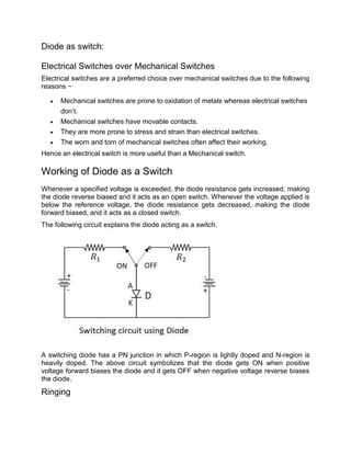
  • 1. Diode as switch: Electrical Switches over Mechanical Switches Electrical switches are a preferred choice over mechanical switches due to the following reasons −  Mechanical switches are prone to oxidation of metals whereas electrical switches don’t.  Mechanical switches have movable contacts.  They are more prone to stress and strain than electrical switches.  The worn and torn of mechanical switches often affect their working. Hence an electrical switch is more useful than a Mechanical switch. Working of Diode as a Switch Whenever a specified voltage is exceeded, the diode resistance gets increased, making the diode reverse biased and it acts as an open switch. Whenever the voltage applied is below the reference voltage, the diode resistance gets decreased, making the diode forward biased, and it acts as a closed switch. The following circuit explains the diode acting as a switch. A switching diode has a PN junction in which P-region is lightly doped and N-region is heavily doped. The above circuit symbolizes that the diode gets ON when positive voltage forward biases the diode and it gets OFF when negative voltage reverse biases the diode. Ringing
  • 2. As the forward current flows till then, with a sudden reverse voltage, the reverse current flows for an instance rather than getting switched OFF immediately. The higher the leakage current, the greater the loss. The flow of reverse current when diode is reverse biased suddenly, may sometimes create few oscillations, called as RINGING. This ringing condition is a loss and hence should be minimized. To do this, the switching times of the diode should be understood. Diode Switching Times While changing the bias conditions, the diode undergoes a transient response. The response of a system to any sudden change from an equilibrium position is called as transient response. The sudden change from forward to reverse and from reverse to forward bias, affects the circuit. The time taken to respond to such sudden changes is the important criterion to define the effectiveness of an electrical switch.  The time taken before the diode recovers its steady state is called as Recovery Time.  The time interval taken by the diode to switch from reverse biased state to forward biased state is called as Forward Recovery Time.$tfr$$tfr$  The time interval taken by the diode to switch from forward biased state to reverse biased state is called as Reverse Recovery Time. $tfr$$tfr$ To understand this more clearly, let us try to analyze what happens once the voltage is applied to a switching PN diode. The main application of p-n junction diode is in rectification circuits. These circuits are used to describe the conversion of a.c signals to d.c in power supplies. Diode rectifier gives an alternating voltage which pulsates in accordance with time. The filter smoothes the pulsation in the voltage and to produce d.c voltage, a regulator is used which removes the ripples. There are two primary methods of diode rectification:  Half Wave Rectifier  Full Wave Rectifier Table of Contents  Half Wave Rectifier  Working of Half Wave Rectifier  Characteristics of Half Wave Rectifier  Advantages of Half Wave Rectifier  Disadvantages of Half Wave Rectifier
  • 3.  Applications of Half Wave Rectifier  Full Wave Rectifier  Working of Full Wave Rectifier  Characteristics of Full Wave Rectifier  Types of Full Wave Rectifier  Advantages of Full Wave Rectifier  Disadvantages of Full Wave Rectifier  Applications of Full Wave Rectifier  Difference What is Half Wave Rectifier? In a half-wave rectifier, one half of each a.c input cycle is rectified. When the p-n junction diode is forward biased, it gives little resistance and when it is reversed biased it provides high resistance. During one-half cycles, the diode is forward biased when the input voltage is applied and in the opposite half cycle, it is reverse biased. During alternate half-cycles, the optimum result can be obtained. Working of Half Wave Rectifier The half-wave rectifier has both positive and negative cycles. During the positive half of the input, the current will flow from positive to negative which will generate only a positive half cycle of the a.c supply. When a.c supply is applied to the transformer, the voltage will be decreasing at the secondary winding of the diode. All the variations in the a.c supply will reduce, and we will get the pulsating d.c voltage to the load resistor. In the second half cycle, the current will flow from negative to positive and the diode will be reverse biased. Thus, at the output side, there will be no current generated, and we cannot get power at the load resistance. A small amount of reverse current will flow during reverse bias due to minority carriers. Characteristics of Half Wave Rectifier Following are the characteristics of half-wave rectifier: Ripple Factor
  • 4. Ripples are the oscillations that are obtained in DC which are corrected by using filters such as inductors and capacitors. These ripples are measured with the help of the ripple factor and are denoted by γ. Ripple factor tells us the number of ripples presents in the output DC. Higher the ripple factor, more is the oscillation at the output DC and lower is the ripple factor, less is the oscillation at the output DC. Ripple factor is the ratio of RMS value of the AC component of the output voltage to the DC component of the output voltage. γ=(VrmsVDC)2−1 DC Current DC current is given as: IDC=Imaxπ Where,  Imax is the maximum DC load current DC Output Voltage The output DC voltage appears at the load resistor RL which is obtained by multiplying output DC voltage with the load resistor RL. The output DC voltage is given as: VDC=VSmaxπ Where,  VSmax is the maximum secondary voltage Form Factor The form factor is the ratio of RMS value to the DC value. For a half-wave rectifier, the form factor is 1.57. Rectifier Efficiency Rectifier efficiency is the ratio of output DC power to the input AC power. For a half-wave rectifier, rectifier efficiency is 40.6%. Advantages of Half Wave Rectifier  Affordable  Simple connections  Easy to use as the connections are simple  Number of components used are less
  • 5. Disadvantages of Half Wave Rectifier  Ripple production is more  Harmonics are generated  Utilization of the transformer is very low  The efficiency of rectification is low Applications of Half Wave Rectifier Following are the uses of half-wave rectification:  Power rectification: Half wave rectifier is used along with a transformer for power rectification as powering equipment.  Signal demodulation: Half wave rectifiers are used for demodulating the AM signals.  Signal peak detector: Half wave rectifier is used for detecting the peak of the incoming waveform. What is Full Wave Rectifier? Full-wave rectifier circuits are used for producing an output voltage or output current which is purely DC. The main advantage of a full-wave rectifier over half-wave rectifier is that such as the average output voltage is higher in full-wave rectifier, there is less ripple produced in full-wave rectifier when compared to the half-wave rectifier. Working of Full Wave Rectifier The full-wave rectifier utilizes both halves of each a.c input. When the p-n junction is forward biased, the diode offers low resistance and when it is reverse biased it gives high resistance. The circuit is designed in such a manner that in the first half cycle if the diode is forward biased then in the second half cycle it is reverse biased and so on. Characteristics of Full Wave Rectifier
  • 6. Following are the characteristics of full-wave rectifier: Ripple Factor Ripple factor for a full-wave rectifier is given as: γ=(VrmsVDC)2−1 DC Current Currents from both the diodes D1 and D2 are in the same direction when they flow towards load resistor RL. The current produced by both the diodes is the ratio of Imax to π, therefore the DC current is given as: IDC=2Imaxπ Where,  Imax is the maximum DC load current DC Output Voltage DC output voltage is obtained at the load resistor RL and is given as: VDC=2Vmaxπ Where,  Vmax is the maximum secondary voltage Form Factor The form factor is the ratio of RMS value of current to the output DC voltage. The form factor of a full-wave rectifier is given as 1.11 Rectifier Efficiency Rectifier efficiency is used as a parameter to determine the efficiency of the rectifier to convert AC into DC. It is the ratio of DC output power to the AC input power. The rectifier efficiency of a full- wave rectifier is 81.2%. Types of Full Wave Rectifier There are two main types of full-wave rectifiers, and they are:  Two diodes full-wave rectifier circuit (requires a center-tapped transformer and is used in vacuum tubes)  Bridge rectifier circuit (doesn’t require a centre-tapped transformer and is used along with transformers for efficient usage)
  • 7. Advantages of Full Wave Rectifier  The rectifier efficiency of a full-wave rectifier is high  The power loss is very low  Number of ripples generated are less Disadvantages of Full Wave Rectifier  Very expensive Applications of Full Wave Rectifier Following are the uses of full-wave rectifier:  Full-wave rectifiers are used for supplying polarized voltage in welding and for this bridge rectifiers are used.  Full-wave rectifiers are used for detecting the amplitude of modulated radio signals. Difference between Half Wave Rectifier and Full Wave Rectifier Parameter Half Wave Rectifier Full Wave Rectifier Definition The half-wave rectifier is a rectifier which is used for converting the one- half cycle of AC input to DC output A full-wave rectifier is a rectifier which is used for converting both the half cycles of AC input into DC output No. of diodes used 1 2 or 4 depending on the type of circuit Form factor 1.57 1.11 Rectifier efficiency 40.6% 81.2% Ripple factor Ripple factor of a half- wave rectifier is more Ripple factor of a full- wave rectifier is less Frequently Asked Questions – FAQs Why half-wave rectifiers are not used in dc power supply?
  • 8. Half-wave rectifiers are not used in dc power supply because the supply provided by the half-wave rectifier is not satisfactory. What is PIV of a diode in a rectifier circuit? PIV stands for peak inverse voltage and it is the maximum voltage that is possible to occur across the diode when it is operated in reverse biased. What is a ripple in a rectifier circuit? Ripple is defined as the ac component that has a pulsating output in a rectifier. What are the advantages of a bridge rectifier over a center-tapped full-wave rectifier? Following are the three advantages of bridge rectifier over a center-tapped full-wave rectifier:  The TUF of a bridge rectifier is 81.2% while the TUF of a center-tapped is 67.2%.  The output of the bridge rectifier is twice that of the center-tapped full-wave rectifier.  A bridge rectifier as a PIV half of the center-tapped full-wave rectifier. What is the cycle followed by the current in a full-wave rectifier? In a full-wave rectifier, the current flows in the half cycle of the input signal. What happens to the peak current if the value of the shunt capacitor filter is increased? When the value of the shunt capacitor filter is increased, the peak current will also increase in a rectifying diode. Why bridge rectifier is preferred over an ordinary two diodes full-wave rectifier? A bridge rectifier is preferred over an ordinary two diodes full-wave rectifier because:  The PIV is less per diode  There is no need for the centre tap