Digital i cs
•Als PPTX, PDF herunterladen•
0 gefällt mir•132 views

This document discusses the history and development of digital integrated circuits (ICs). It covers the invention of ICs in the 1960s, the development of logic families using different technologies like MOS and CMOS, and the replacement of transistor-transistor logic (TTL) by CMOS in the 1990s. Key logic technologies discussed include diode logic, TTL, emitter-coupled logic, and BiCMOS logic. The document also covers concepts like propagation delay, setup time, and hold time.

Empfohlen
Weitere ähnliche Inhalte
Was ist angesagt?
Was ist angesagt? (19)
Andere mochten auch
Andere mochten auch (16)
Ähnlich wie Digital i cs
Ähnlich wie Digital i cs (20)
Kürzlich hochgeladen
Kürzlich hochgeladen (20)
Digital i cs
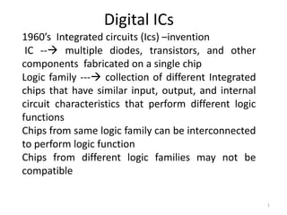
- 1. Digital ICs 1960’s Integrated circuits (Ics) –invention IC -- multiple diodes, transistors, and other components fabricated on a single chip Logic family --- collection of different Integrated chips that have similar input, output, and internal circuit characteristics that perform different logic functions Chips from same logic family can be interconnected to perform logic function Chips from different logic families may not be compatible 1
- 2. Speed Power consumption cost MOS --- 10 years before the BJT invention principles of MOS are patented lagged BJT in speed but lower power consumption and higher level of integration mid-1980s Complementary MOS Higher speed low power consumption 2
- 3. 3
- 4. Small to medium scale integration ------TTL was the choice TTL was largely replaced by CMOS in 1990s 4
- 5. Digital ICs Bipolar Logic ---- Diodes and transistors Diode logic (DL) ---- Diodes and resistors – to perform logic operations Transistor-transistor logic (TTL) --- transistors both to perform logic functions and to boost output drive capability. Emitter-Coupled logic ---transistors as current switches to achieve very high speed BiCMOS logic - bipolar and MOS transistors- input and logic circuits are CMOS for low power consumption, outputs use bipolar transistors to achieve higher driving capability 5
- 6. CMOS logic ------ logic circuit operates on 5 V power supply 6
- 7. Various Series within CMOS family 7
- 8. TTL Logic 8
- 9. Various Series within TTL family 9
- 10. DIODE Logic 10
- 11. 11
- 12. Diode AND gate 12
- 13. 13
- 14. 14
- 15. 15
- 16. Bipolar Junction Transistors 16
- 17. 17
- 18. Mode EBJ CBJ Active Forward Reverse Cutoff Reverse Reverse Saturation Forward Forward 18
- 19. 19
- 20. 20
- 21. 21
- 22. 22
- 23. Storage time --- Propagation delay 23
- 24. The propagation delay of a signal path is the amount of time it takes for a change in the input signal to produce a change in the output signal. 24
- 25. 25
- 26. Setup time is the minimum time interval for which the input signal must be stable prior to the sampling event of the clock for the input signal to be recognized correctly hold time is the minimum time interval for which the input signal must be stable following the sampling event of the clock for the input signal to be recognized correctly 26
- 27. 27
- 28. Transistor-transistor logic Multiple-emitter transistor 28
- 29. DTL Gates 29