Rotating machines part 4
•Als DOCX, PDF herunterladen•
1 gefällt mir•332 views

Permanent magnet DC motor

Empfohlen
Weitere ähnliche Inhalte
Was ist angesagt?
Was ist angesagt? (20)
Andere mochten auch
Andere mochten auch (20)
Ähnlich wie Rotating machines part 4
Ähnlich wie Rotating machines part 4 (20)
Kürzlich hochgeladen
Kürzlich hochgeladen (20)
Rotating machines part 4
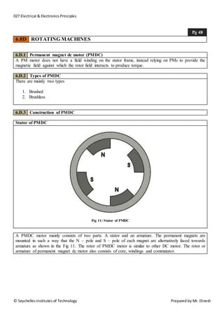
- 1. 027 Electrical & Electronics Principles © Seychelles Institutes of Technology Prepared by Mr. Dinesh Pg 48 6.0D ROTATING MACHINES 6.D.1 Permanent magnet dc motor (PMDC) A PM motor does not have a field winding on the stator frame, instead relying on PMs to provide the magnetic field against which the rotor field interacts to produce torque. 6.D.2 Types of PMDC There are mainly two types 1. Brushed 2. Brushless 6.D.3 Construction of PMDC Stator of PMDC Fig 11: Stator of PMDC A PMDC motor mainly consists of two parts. A stator and an armature. The permanent magnets are mounted in such a way that the N – pole and S – pole of each magnet are alternatively faced towards armature as shown in the Fig 11. The rotor of PMDC motor is similar to other DC motor. The rotor or armature of permanent magnet dc motor also consists of core, windings and commutator.
- 2. 027 Electrical & Electronics Principles © Seychelles Institutes of Technology Prepared by Mr. Dinesh Pg 49 6.0D ROTATING MACHINES 6.D.4 Working principle of PMDC The working principle of PMDC motor is just similar to the general working principle of DC motor. When a carrying conductor comes inside a magnetic field, a mechanical force will be experienced by the conductor and the direction of this force is governed by Fleming’s left hand rule. As in a permanent magnet dc motor, the armature is placed inside the magnetic field of permanent magnet; the armature rotates in the direction of the generated force. Here each conductor of the armature experiences the mechanical force F = B.I.L Newton where B is the magnetic field strength in Tesla (weber / m2), I is the current in Ampere flowing through that conductor and L is length of the conductor in metre comes under the magnetic field. Each conductor of the armature experiences a force and the compilation of those forces produces a torque, which tends to rotate the armature. 6.D.5 Equivalent circuit of PMDC The supply voltage to the armature will have armature resistance drop and rest of the supply voltage is countered by back emf of the motor. Hence voltage equation of the motor is given by, V = IR + Eb Where, V : the supply voltage I : armature current R : armature resistance of the motor Eb : back emf
- 3. 027 Electrical & Electronics Principles © Seychelles Institutes of Technology Prepared by Mr. Dinesh Pg 50 6.0D ROTATING MACHINES 6.D.6 Advantages of PMDC 1. No need of field excitation arrangement. 2. No input power in consumed for excitation which improves efficiency of dc motor. 3. No field coil hence space for field coil is saved which reduces the overall size of the motor. 4. Cheaper and economical for fractional kW rated applications. 6.D.7 Disadvantages of PMDC 1. The magnetic strength of the field may get weak due to demagnetizing effect armature reaction. 2. There is also a chance of getting the poles permanently demagnetized. 3. The field in the air gap is fixed and limited and it cannot be controlled externally. 6.D.8 Application of PMDC Automobiles starter Toys Wipers Washers Hot blowers Air conditioners Computer disc drives and in many more
- 4. 027 Electrical & Electronics Principles © Seychelles Institutes of Technology Prepared by Mr. Dinesh Pg 51 6.0D ROTATING MACHINES 6.D.9 Exploded view of a permanent magnet dc motor
- 5. 027 Electrical & Electronics Principles © Seychelles Institutes of Technology Prepared by Mr. Dinesh Pg 52 6.0D ROTATING MACHINES 6.D.10 Brushed dc permanent magnet motor
- 6. 027 Electrical & Electronics Principles © Seychelles Institutes of Technology Prepared by Mr. Dinesh Pg 53 6.0D ROTATING MACHINES 6.D.12 Circuit diagram of a 2 pole brushed dc permanent magnet motor 6.D.13 Working principle of a 2 pole brushed dc permanent magnet motor (BDC) The construction of a simple BDC motor is made of the same basic components: a stator, rotor, brushes and a commutator. The stator generates a stationary magnetic field that surrounds the rotor. This field is generated by either permanent magnets or electromagnetic windings. The rotor, also called the armature, is made up of one or more windings. When these windings are energized they produce a magnetic field. The magnetic poles of this rotor field will be attracted to the opposite poles generated by the stator, causing the rotor to turn. As the motor turns, the windings are constantly being energized in a different sequence so that the magnetic poles generated by the rotor do not overrun the poles generated in the stator. This switching of the field in the rotor windings is called commutation.
- 7. 027 Electrical & Electronics Principles © Seychelles Institutes of Technology Prepared by Mr. Dinesh Pg 54 6.0D ROTATING MACHINES 6.D.14 Solved questions brushed permanent magnet dc motor Work example 1 Explain how a brushed dc motor works? Solution Circuit diagram of a brushed dc permanent magnet motor Explanation The moving part of motor (rotor) turns inside the fixed part the frame or stator. The rotor includes armature, commutator and shaft. The current in wires (windings) runs through slots in the armature create magnetic fields that acts against the fixed magnetic field on the magnetic poles on the stator to turn the armature, and thus the whole rotor. The shaft is in the centre is used to apply this rotation externally. Electricity is fed to the armature via brushes on rotor that rub against the commutator (electrical contact on the rotor).
- 8. 027 Electrical & Electronics Principles © Seychelles Institutes of Technology Prepared by Mr. Dinesh Pg 55 6.0D ROTATING MACHINES 6.D.15 Brushed dc permanent magnet motor design for trains 6.D.16 Application of brushed dc motors Toys Toothbrushes Shavers Cordless tools Small fans
- 9. 027 Electrical & Electronics Principles © Seychelles Institutes of Technology Prepared by Mr. Dinesh Pg 56 6.0D ROTATING MACHINES 6.D.17 Structure of a brushless dc motor 6.D.18 Working principle of brushless dc motor Brushless dc motor motors are a type of synchronous motor. This means the magnetic field generated by the stator and the magnetic field generated by the rotor rotates at the same frequency. The rotor, made of a magnet, is rotated by magnetic fields that are generated by the current flowing through the stator windings. The current is switched by the sensor and electronic circuit. 6.D.19 Application of brushless dc motor Linear actuators Servomotors Actuators for industrial robots Extruder drives motor Feed drives for CNC machine tools
- 10. 027 Electrical & Electronics Principles © Seychelles Institutes of Technology Prepared by Mr. Dinesh Pg 57 6.0D ROTATING MACHINES 6.D.20 Solved questions brushed permanent magnet dc motor Work example 1 What is the difference between a brushed and a brushless dc motor? Solution Explanation A Brushed Motor has a rotating set of wound wire coils (armature) which acts as an electromagnet with two poles. A mechanical rotary switch (commutator) reverses the direction of the electric current twice every cycle, to flow through the armature so that the poles of the electromagnet push and pull against the permanent magnets on the outside of the motor. As the poles of the armature electromagnet pass the poles of the permanent magnets, the commutator reverses the polarity of the armature electromagnet. During the instant of switching polarity, inertia keeps the motor going in the proper direction. A Brushless Motor uses a permanent magnet external rotor, three phases of driving coils, one or more devices to sense the position of the rotor, and the associated drive electronics. The coils are activated, one phase after the other, by the electronic speed controller as cued by the signals from the rotor position sensors.