

Empfohlen
Weitere ähnliche Inhalte
Was ist angesagt?
Was ist angesagt? (20)
Andere mochten auch
Andere mochten auch (9)
Ähnlich wie Dhruvin kurilpa bridge
Ähnlich wie Dhruvin kurilpa bridge (20)
Mehr von Dhruv Seth
Mehr von Dhruv Seth (20)
Kürzlich hochgeladen
Kürzlich hochgeladen (20)
Dhruvin kurilpa bridge
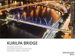
- 1. KURILPA BRIDGE BRISBANE, AUSTRALIA COX RAYNER ARCHITECTS AND ARUP TENSEGRITY BRIDGE STRUCTURE DHRUVIN SHAH 08-25
- 2. • It is a modified version of a conventional cable-stayed bridge structure • Program - Pedestrian and cycle bridge • Bridge utilizes Buckminster Fuller’s principle of tensegrity producing a synergy between balanced tension and compression components to create an incredibly strong and light structure.
- 3. DESIGN • Form of the bridge driven by – Landing points – River clearance – Traversing roads – Maximum permitted grade of disabled user access • Length – 470m • Main central span – 128m • Width – 6.5m • As a result structural depth restricted from top of the deck limited to less than 1m • Inspiration from Buckminster Fuller’s tensegrity structures • Arrangement of masts and cables was developed
- 5. DESIGN - THE BRIDGE CAN BE THOUGHT OF AS: • A modified version of a conventional cable-stayed bridge structure • Comprising a series of staggered masts and major cables • In conjunction with the 6.5m clear width composite steel • Concrete deck spans between the support piers • A true tensegrity array of compression struts (spars) and secondary cables that laterally stabilize the masts, provide torsional rigidity to the bridge spans, and support the integrated canopy that provides shade for bridge users
- 7. STRUCTURAL SYSTEM • The 120m long Kurilpa Point approach is a reinforced concrete spiral ramp structure comprising seven spans up to 20m supported on reinforced concrete blade piers. • The deck cross section tapers from a central 780mm deep spine to 280mm deep edges. • The Kurilpa Point approach is separated from the tensegrity river spans and the Kurilpa Point landing abutment by expansion joints and bearings that allow the approach to expand and contract with minimal restraint from the adjoining sections.
- 8. COMPONENTS • A composite steel and concrete deck structure • A series of steel masts and cables • An integrated tensegrity array of steel ties • Flying struts (spars) • A steel framed tensegrity canopy
- 9. CONSTRUCTION • One of the unique aspects of the Kurilpa bridge is that span over major river and road corridors is the need for the structure to support itself at each stage of the erection, without reliance upon temporary props and scaffolding • Structurally this span composition is approximately balanced eliminating the need for massive abutments and allowing the tensegrity structure to be constructed via a balanced cantilever technique. • Tie downs are provided at the outer ends of the side spans to counter the weight supported over the large river span. • Support points flanking the navigational channel are more conventional with reinforced concrete twisted blade piers on pile caps in the river. • At each of these locations permanent rock anchors secure the concrete filled tubular steel piles to resist the design ship impact forces.
- 10. TENSEGRITY ARRAY OF FLYING STRUTS AND CABLES They fulfill three critical functions: • Tensegrity struts (steel circular hollow sections) and cables suspend the canopy, allowing it to float above the deck with no apparent means of support • Tensegrity struts and cables laterally restrain the tops of the primary and secondary masts, preventing them from buckling sideways under the loads arising from the suspension of the deck and lateral wind and seismic loads • Tensegrity struts and cables work in unison with the major and minor masts and cables to resist twisting forces and lateral forces arising from patch loads on the deck (for example crowds gathering on one side of the deck), wind loads and earthquake loads.