
Empfohlen
Weitere ähnliche Inhalte
Was ist angesagt?
Was ist angesagt? (20)
Ähnlich wie Photodiode / diode
Ähnlich wie Photodiode / diode (20)
Mehr von DheerendraKumar43
Kürzlich hochgeladen
Kürzlich hochgeladen (20)
Photodiode / diode
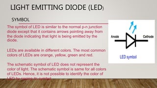
- 1. LIGHT EMITTING DIODE (LED) SYMBOL The symbol of LED is similar to the normal p-n junction diode except that it contains arrows pointing away from the diode indicating that light is being emitted by the diode. LEDs are available in different colors. The most common colors of LEDs are orange, yellow, green and red. The schematic symbol of LED does not represent the color of light. The schematic symbol is same for all colors of LEDs. Hence, it is not possible to identify the color of LED by seeing its symbol.
- 2. • CROSS SECTIONAL VIEW OF LED-
- 3. LED OPERATION • . A light-emitting diode is a two-lead semiconductor light source. It is a p–n junction diode that emits light when activated. When a suitable voltage is applied to the leads, electrons are able to recombine with electron holes within the device, releasing energy in the form of photons. This effect is called electroluminescence, and the color of the light (corresponding to the energy of the photon) is determined by the energy band gap of the semiconductor. Different wavelengths involved in the process determine the different colors produced from the LEDs. Hence, light emitted by the device depends on the type of semiconductor material used. Infrared light is produced by using Gallium Arsenide (GaAs) as a semiconductor. Red or yellow light is produced by using Gallium-Arsenide-Phosphorus (GaAsP) as a semiconductor. Red or green light is produced by using Gallium-Phosphorus (GaP) as a semiconductor.
- 4. APPLICATION
- 5. TUNNEL DIODE *SYMBOL OF TUNNEL DIODE* A Tunnel diode is a heavily doped p-n junction diode in which the electric current decreases as the voltage increases. In tunnel diode, electric current is caused by “Tunneling”. The tunnel diode is used as a very fast switching device in computers. It is also used in high-frequency oscillators and amplifiers. The circuit symbol of tunnel diode is shown in the below figure. In tunnel diode, the p-type semiconductor act as an anode and the n-type semiconductor act as a cathode
- 6. CROSS SECTIONAL VIEW OF TUNNEL DIODE-
- 7. *OPERATION OF TUNNEL DIODE - In tunnel diode, the valence band and conduction band energy levels in the n-type semiconductor are lower than the valence band and conduction band energy levels in the p-type semiconductor. Unlike the ordinary p-n junction diode, the difference in energy levels is very high in tunnel diode. Because of this high difference in energy levels, the conduction band of the n-type material overlaps with the valence band of the p-type material. Quantum mechanics says that the electrons will directly penetrate through the depletion layer or barrier if the depletion width is very small. The depletion layer of tunnel diode is very small. It is in nanometers. So the electrons can directly tunnel across the small depletion region from n- side conduction band into the p-side valence band. In ordinary diodes, current is produced when the applied voltage is greater than the built-in voltage of the depletion region. But in tunnel diodes, a small voltage which is less than the built-in voltage of depletion region is enough to produce electric current. In tunnel diodes, the electrons need not overcome the opposing force from the depletion layer to produce electric current. The electrons can directly tunnel from the conduction band of n-region into the valence band of p- region. Thus, electric current is produced in tunnel diode.
- 8. APPLICATION OF TUNNEL DIODE TUNNEL DIODES ARE USED AS LOGIC MEMORY STORAGE DEVICES. TUNNEL DIODES ARE USED IN RELAXATION OSCILLATOR CIRCUITS. TUNNEL DIODE IS USED AS AN ULTRA HIGH-SPEED SWITCH. TUNNEL DIODES ARE USED IN FM RECEIVERS.
- 9. PHOTODIODE A PHOTODIODE IS A SEMICONDUCTOR DEVICE THAT CONVERTS LIGHT INTO AN ELECTRICAL CURRENT. THE CURRENT IS GENERATED WHEN PHOTONS ARE ABSORBED IN THE PHOTODIODE. PHOTODIODES MAY CONTAIN OPTICAL FILTERS, BUILT-IN LENSES, AND MAY HAVE LARGE OR SMALL SURFACE AREAS.
- 10. SYMBOL OF PHOTODIODE THEY HAVE TWO TERMINALS COMING FROM THE END. THE SMALLER END OF THE DIODE IS THE CATHODE TERMINAL, WHILE THE LONGER END OF THE DIODE IS THE ANODE TERMINAL. SEE THE FOLLOWING SCHEMATIC DIAGRAM FOR THE ANODE AND CATHODE SIDE. UNDER FORWARD BIAS CONDITION, CONVENTIONAL CURRENT WILL FLOW FROM THE ANODE TO THE CATHODE, FOLLOWING THE ARROW IN THE DIODE SYMBOL. PHOTOCURRENT FLOWS IN THE REVERSE DIRECTION. • TYPES OF PHOTODIODE • PN Photodiode • Schottky Photo Diode • PIN Photodiode • Avalanche Photodiode
- 11. WORKING OF PHOTODIODE • The working principle of a photodiode is, when a photon of ample energy strikes the diode, it makes a couple of an electron-hole.This mechanism is also called as the inner photoelectric effect. If the absorption arises in the depletion region junction, then the carriers are removed from the junction by the inbuilt electric field of the depletion region.Therefore, holes in the region move toward the anode, and electrons move toward the cathode, and a photocurrent will be generated.The entire current through the diode is the sum of the absence of light and the photocurrent. So the absent current must be reduced to maximize the sensitivity of the device.
- 12. V-I CHARACTERISTICS OF PHOTODIODE
- 13. WHY ARE THEY USED??? • These diodes are widely used in the applications where the detection of the presence of light, color, position, intensity is required. The main features of these diodes include the following. • The linearity of the diode is good with respect to incident light • Noise is low. • The response is wide spectral • Rugged mechanically • Light weight and compact • Long life
- 14. APPLICATIONS OF PHOTODIODE • These diodes are used in consumer electronics devices like smoke detectors, compact disc players, and televisions and remote controls in VCRs. • Photodiodes are frequently used for exact measurement of the intensity of light in science & industry. Generally, they have an enhanced, more linear response than photoconductors. • These diodes are much faster & more complex than normal PN junction diodes and hence are frequently used for lighting regulation and in optical communications. • In other consumer devices like clock radios, camera light meters, and street lights, photoconductors are more frequently used rather than photodiodes.