

Empfohlen
Weitere ähnliche Inhalte
Was ist angesagt?
Was ist angesagt? (20)
Ähnlich wie Pentair #320 chlorinator manual
Ähnlich wie Pentair #320 chlorinator manual (20)
Pentair #320 chlorinator manual
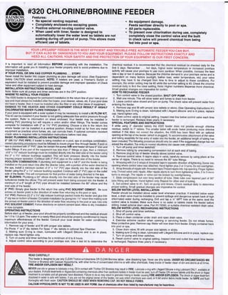
- 1. RAINBOW- LIFEGARD" Yz fi #s2o cHLoRtNE/BRoMtNE FEEDER Features: . No special venting required. . Completely enclosed-no escaping gases. . Positive external no-clog control valve. . When used with timer, feeder is designed to automatically lower the water level so tablets are not soaking during off period of pump.This allows more efficient use of tablets. No equipment damage. Feeds sanitizer directly to pool or spa. All parts replaceable. To prevent over chlorination during use, completely completely close the control valve and the built in check valve will prevent chemical from being fed into pool or spa. YOUR LIFEGARD@ FEEDER ISTHE MOST EFF|CTENT ANDTROUBLE-FREE AUTOMATTC FEEDERyOU CAN BUy BUT IT CAN ALSO BE DANGEROUSTOYOU ANDYoUR EQUIPMENT. PLEASE FoLLoW INsTRUcTIoNs EXACTLY AND HEED ALL CAUTIONS.YOUR SAFETY ANDTHE PROTECTION OFYOUR EQUIPMENT IS OUR FIRST CONCERN. It is important to read all information BEFORE proceeding with the installation. The information will guide you in installing your feeder properly and to avoid problems due to improper installation. IFYOUR POOL OR SPA HAS COPPEH PLUMBING .. , STOPII Never install the feeder into copper plumbing as pipe damage will occur. (See Equipment Safety CAUTION sheet enclosed). NOTE: lf heaters are used, a Fireman's Switch or equivalent must be installed to prevent possible damage and improper operation of Check Valve and other equipment subject to heat damage. INSTALLATION INSTRUCTIONS MODEL #320 Note: Make sure all pumps and timer switches are in the OFF position. WHERE TO INSTALL YOUR FEEDER in the return line of your new pool or cleaner, valves, etc. lf your pool does ?'""+ 8#li;' f; ESt i+''l''fi il"'il" CHLORINATED WATER FLOWS THROUGH IT. lf your pool is equipped with a solar system it may be necessary to install a Hl FLOW KlT. This kit can be installed if your feeder is not getting adequate flow and/or pressure through the system. Refer to information on sheet enclosed. Your feeder may be installed in existing PVC plumbing but will require a union and/or other fittings. The feeder comes complete for installation with 2" or 1yz' PVC plumbing. Choose a site in the return line where feeder can be installed in a vertical position. Always install as far from any metal equipment as practical since fumes, etc. can corrode them. lf optional corrosion resistant check valve is required refer to installation instructions before next steo. BASIC PLUMBING INSTALLATION INSTRUCTIONS 2' eder is being installed on a pool, spa or pool/spa combination, co must be followed to insure proper flow through leeder. lf pool or sp pipe, be eertain the pumpiflftlrahd heateralliave2" iniet and the spa, install a side of the feeder using the.2 n the ouflet side of the feeder. the spa. 90'ELBOWS: Pl mav cause turbulence inside e feeder. A minimum of a 6" length of PVC pipe should be installed between the g0" elbow and the inlet side of the feeder. 2" PVC: Simply glue feeder to the return line using pVC SOLVENT CEMENT. Be sure o x OPERATING INSTRUCTIONS Before start up of feeder, your pool should be properly conditioned and the residual should be 1 .0 to I .5 ppm. The water in a newlyJilled pool should be properly conditioned to insure maximum eftectiveness of the feeder. Consult your local dealer for water conditioning information for your area. 1. Remove cap of feeder and fill with proper size tablets. For Pools: 1" or 3" dia. tablets For Spas: 1" dia. tablets in optional Spa Chamber. 2. Making sure O-ring is clean, lubricated with Lifegard Silicone and is an in place, replace cap. Hand tighten only. 3. Turn on pump and timer switches for a minimum of 6 to 8 hours. 4. Adjust control valve according to your pool/spa size. Use a test kit to determine the chemical residual. lt is recommended th lv for the first 5 days. Remember . . . hot days, pool/spa activity will cause your pool/spa to use the feed rate a day or two in advance. Because the chlorine demand in your pool/spa varies and is dependent on many factors (sunlight, bather load, water temperature, etc) your valve setting may have to be changed from time to time to adjust to these conditions. For may be #2 while the summer setting is #3. Check the chlorine eal setting. Note: Higher numbers dispense more chemical. imoerative for control. HOWTO RECHARGE FEEDER 1. Turn control valve to the closed position. SHUT OFF pUMp. 2. Wait one minute. This will allow water and fumes to drain from feeder. 3. Leave control valve closed and turn on pump. The check valve will prevent water from entering the feeder. 4. Remove cap and fill with proper size tablets or sticks. (See Operating Instructions #1) 5. Making sure O-ring is clean, lubricated with Lifegard silicone and is in place, replace cap. Hand tighten only. 6. open control valve to original setting. Inspect inlet line below control valve each time leeder is recharged. Replace lines yearly if necessary, SPECIAL FEATURES AND INSTRUCTIONS lf while using 3" chlorine residual, switch to chlorine residual. lf this do oDtional opening at the top he valve and tubing assembly for top der, an additional length of tubing has been included. The following used if the suggested change has not solved the situation. Top entr cause over chlorination. 1. Turn otf pump and timsr swltolieB. 2. Remove tubing by unscrewing compression nut at each end of tubing 3. Remove plug at top of feeder directly above control valve. 4. Remove control valve. It nipple stays in valve, carefully remove by using pliers at the center of nipple. There is no need to remove the 90. tube fittings. BELOW WATEB LEVEL INSTALLATION Feeder should be installed above water level whenever practical. lf installed below water level, a drain valve must be installed to prevent spillage and dangerous splash back of high chlorinated water during recharging. Drill and lap a %" MpT hole at the same level the control valve is located. Make sure there is no water or tablets inside the feeder before drilling. Install optional drain valve, Part R172060, or suitable chemical resistant drain valve. BELOW WATER LEVEL RECHARGING INSTRUCTIONS 1. Shut off pump and timer switches. 2. Shut off control valve. 3. Place a clean container under drain and open drain valve. 4. Exercise extreme caution when opening or servicing feeder. Do not inhale fumes. wear protective gear. Remove cap. water will now drain from feeder. Empty container back into pool or spa. 5. Close drain valve. fill with proper size tablets or sticks. 6. Making sure O-ring is clean, lubricated with Lifegard Silicone and in in place, replace cap. 7. Turn on pump and timer switches. 8. Reset control valve to original setting. Inspect inlet and ouilet line each time feeder is recharged. Replace lines yearly if necessary. This feeder is designed.to use.only CLEAN Trichlor'slrizinetrione 0H CLEAN Bromine tables - slow dissolving type. Never use dirty tablets. UNDER NO CIBCUMSTANCES MIX Trichlor or Bromine with Calcium Hypochlorite, with other forms of concentrated chlorine or with other chehiials. Keep inside bf feeder clean ol dirt and debris at all times, FIRE AND/OR EXPLOSION MAY RESULT. with Lifegard Silicone o-ring Lubrjcant ONLy, available ar urn off Feeder OR remove tablets until the shock or Aloae BE AND/OR EXPLOSION. The shock or algae treatm-ent , or if dirt and/or debris inside feeder, be SAFE and Ilush CALCIUM HYPOCHLORITE lS NOT T0 BE USED lN ANY FORM. Use of chemicals other than listed by manufacturer may be hazardous.
- 2. #320 CHLORINE / BROMINE FEEDER PARTS BREAK DOWN DRAWING Bromine Standpipe Installation To increase erosion of small bromine tablets, install Bromine Standpipe as follows: 1. Remove screen from bottom of chamber exposing check valve (F) 2. Insert adapter (T) into check valve opening. 3. Cut supplied 5/s" black tube (Q) to 6" length and push tube into adapter opening, Item Part No. Optional Spa Chamber: For use on spas and hot tubs only. Use 1 " diameter tabs. lnsert into feeder slotted end down. Available from your dealer, B D E F G H I K K1 .L M N P o R S T 1 1 Optional '1 1 1 1 R172008W R1 72009 P.172331 R01 052 R172248 R172317 R172256 R.172086 R172272 R172091 R1 71 097 R172210 R172037 R1 72036 R172258 R172134 R172253 1 R172319 Optional R172288 1 R1720488 3" Threaded cap 3" O-Ring #320 Body only (new) Lock screw Check valve Divertor tee 72" x Short MPT nipple 72" Chlorine control valve 72" NPT x tube fitting Wnut 5/e" OD Chlorinator tube Tube support spring 2"xl1z"sxsbushing Spa chamber Silicone lubricant Screen 72" MPT PVC plug 5/s" OD 18" tube (optional top feed) Bottom O-ring 172" Corrosion resistant check valve Standpipe adapter YOU MAY SUBSTITUTE BROMINE TABLETS OR STICKS FOR TRICHLOR IN THIS FEEDER. DO NOT MIX. CALCIUM HYPOCHLORITE IS NOTTO BE USED IN ANY FORM. (1{Sr.) NSF listed for oublic or residential use in Swimming Pools, Spas or Hot Tubs using Trichlor or Bromine and when used with a flow indicating device such as Rainbow Lifegard Model #R172276. Technical Support: (800) 83 1 -7 1 33 IMPORTANT OPTION. SEE CORROSION CAUTION SHEET. CAUTION Do not install feeder into copper plumbing. Pipe damage could occur. Never install feeder before heater. Heater damage could occur, *Not used with 2" PVC, for 1/2" PVC only. '*Be sure screen has not come loose in shipment-if loose: Simply snap over 4 posts in bottom of chlorinator to reDlace. NOTE: To service check valve F. Remove lockscrew E. and unscrew (counter-clockwise) D chlorinator body from G divertor tee. Typical Installation #320 with heater. Typical Installation #320 without heater ARAINBOW", LIFEGARD YZ Pentair Water Pool and Spa' K @ 2012 Pentair Water Pool and Spa, Inc. All rights reserved R24048-1200
- 3. HI FLO FEEDER KIT #R171099 FOR MODELS #320 & #322 DIRECTIONS 1. Turn off pump and timer switches. 2. Loosen compression nut and remove Feeder tube and 90' elbow from the diverter tee at base of Feeder. 3. Using thread seal tape as thread sealant, wrap /2" MPT plug threads (1) with several turns of the tape only. Install in place place of 90" elbow on diverter tee. 4. Disconnect other end of Feeder tube from control valve g0' elboq by loosening compression nut. Use the compression nuts from old tube to attach new 6'section (2). 5. Push compression nut over tubing end, then push tubing onto tapered end of elbow. Tighten nut firmly by hand. 6. Connect other end of plumbing. IF PoousPA HAS A HEATER,INSTALL BETWEEN FTLTER AND HEATER. tF YOUR POOUSPA HAS A SOLAR SYSTEM,INSTALL BEFORE SOLAR SYSTEM INLET LINE.lF NO HEATER,INSTALL BETWEEN PUMP AND FILTER. Drill e/ro" hole in plumbing, remove burrs, and install saddle clamp assembly. (See illustration)Tighten clamp with screwdriver. Slide smail stainless steel clamp #3 over tubing #2 and slide tubing over saddle tube fitting #4. Secure tubing to fitting by tightening camp with screwdriver. Make sure clamp is below rib at end of saddle tube fitting. 7. To install y2' CHECKVALVE, cut tube approximately 6" away from plumbing connection. Remove compresSion nuts from check valve. Slide nuts over both ends of tube. Insert check valve endi into both pieces of tubing and tighten compression nuts firmly by hand. Be sure arrow "FLOW" is pointing toward the Feeder. Hr FLO FEEDER KtT #R171099 PARTS BREAKDoWN DRAWING Item Ouantity Part No. Description 1 2 3 4 5 o 7 1 6r' 1 R172134 R1 72093 R1 7501 3 R171162 R172263 R172264 R172324 Plug,7z" MPJ Tube, /2" lD Chlorinator Clamp, S.S. Tubing Fitting, Saddle Tube Gasket, Saddle Clamp, Saddle Valve, /2" Tube check 1 1 1 1 e/ro" Hole in NOTE: When using this kit with a pool/spa combination (to prevent draining spa) shut off Feeder control valve when onlv the spa is in use. ry- Plumbing . [P P"tttair lrUater Pool and Spa" @ 2012 Pentair Water Pool and Spa, ln<. All rights reserved Technical Support: (800) 831 -71 33 R24079-1200
- 4. EXTENSIONS . Going on vacation? . Need more chlorine? . Filling Chlorinator/Brominator too frequenily? LIFEGARD CHLORINATOR EXTENSIONS SOLVE THE ABOVE PROBLEMS BY: 1, Increasing tablet capacity. 2. Larger chamber size allows more erosion of tablets. (See special instructions below) The 10" extension doubles and the 20" extension triples (approximately) the capacity and time between refills. *AVAILABLE THRoucH LTFEGARD DEALERS oNLy. NOTE: On free standing #300 series chlorinators, the base of the chlorinator should be secured to prevent the possibility of the chlorinator tipping over due to increased height. INSTALLATION INSTRUCTIONS 1. Follow recharging instructions to the point of filling with tablets 2. Making sure O-Ring is clean, lubricated with Lifegard Silicone and in place, screw on extension tightly and secure with lock screw. (You may wish to wait until back in operation before tightening charging procedure. --ThdJarge-ehamber size-will-result in-more-ehlorine-being dispensedat-the- same valve setting, therefore, once installed, several days monitoring will _!/necessary to readjust chlorinator output. Parts Breakdown Drawing Item Ouantlty Part No. Descrlptlon 1 1 R172078 Lockscrew (bottom collar) 2 1 R172009 O-Ring I -'*0,n' 2 #R172087 #R172283 20" Chlorinator extension complete10" Chlorinator extension complete R24054-1200
- 5. #R172288 SPRING C 11/2" & 2u S LIP HECK VALVE a a a o special corrosion resistant 1y2' & 2" slip spring check valve can be used to check back flow of fluids, air, etc. Full free flow design Special Spring and Seal for corrosive applications. Enclosed spring insuring free operation. Very effective when used in conjunction with chlorinator to check back flow of chemicals to pool/spa equipment, preventing corrosion problems and damage. Can be mounted in any position. CHECK VALVE Typical check valve installation NOTE: lf heaters are used, a Fireman's Switch or other safety device must be installed to prevent possible damage and improper operation of Check Valvelnd other equipment subject to heat damage. ln line Chlorinator Return line to pool/spa Technical Support: (800) 831 -71 33 & *rrrairwaterPool and Spa' @ 2012 Pentair Water Pool and Spa, Inc. All rights reserved R24049-0201
- 6. EQUIPMENT SAFETY CAUTION! PLEASE READ CAREFULLY Since most pool's plumbing is not airtight, and a mixture of air and chlorine is highly corrosive to metals, it is important to protect these items from corrosion in the OFF period when no circulation is taking place. (There is no chance for chlorine corrosion when the circulating system is in operation.) Of course, corrosion or erosion of metal components can still occur independently of any chlorinator installation for the following reasons: 1. Water velocity too high. 2. Water pH less than 7.2. 3. Total alkalinity less than 100 PPM. lf your pool or spa has any of the following equipment, special plumbing procedures must be followed for safe operation: 1. Brass or bronze gate, rotary or backwash valves. 2. The preceding valves constructed of PVC or other plastic material with metallic shafts. 3. Filters, heaters, heat exchanges or other items with metallic tanks, shafts. coils or tubes. 4. NOT FOR USE IN COPPER PLUMBING. lnstallation of thd OPTIONAL Rainbow #R172288 positive seal, corrosion resistant check valve SHOWN ON REVERSE SIDE will prevent the backflow of corrosive liquids and gases that can damage equipment containing metallic components. Examples listed above. WARNING: lf your pool is equipped with a permanent built in pool-cleaning system, damage could occur to that system if materials are not compatible with low pH Tri-Chloro feeders. Check with manufactu rer for compatibi lity. Technical Support: (800) 831 -71 33 , o 2012 PentairWater Pool and Spa,lnc.All rights reserved 1620 Hawkins Ave.,Sanford, NC27330. (919) 566-8000 10951 West Los Angeles Ave.,Moorpark,CA 93021 . (805) 553-5000 Pool and Spa' Rainbow LifeGuardrM and Pentair Water Pool and Spao is a trademark and/or a registered trademark of Pentair Water Pool and Spa, Inc. and/or its affiliated companies in the United States and/or other countries. Unless noted, names and brands of others that may be used in this document are not used to indicate an affiliation or endorsement between the proprietors of these names and brands and PentairWater Pool and Spa, Inc.Those names and brands may be the trademarks or registered trademarks of those parties or others. I lllillll llllill llll lilllllll llilllll R242eo . Rev D os oe.12 @&*,roirwater