2. Introduction
• Strict emission standards require precise
fuel delivery
• Computers used to calculate fuel needs
• EFI very precise, reliable & cost effective
• EFI provide correct A/F ratio for all loads,
speeds, & temp ranges
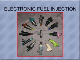
3. The Fuel Injector
• Electromechanical device
• Controlled by PCM
• Engine rpm determines when injector
opens
• How long it stays open determined by:
– Engine temp
– Engine load
– Throttle pos.
– O2 sensor voltage
4. Throttle Body Injection (TBI)
• First injection
unit used
• Housing similar
to Carb
• One or two
injector
• One or two of
these units
mounted to
intake manifold
FIG 6-40 CLASS
7. Multi-Port Fuel Injection
• One injector per cylinder
• Mounts in intake
manifold, sprays directly
at intake valve
• Fired in groups or
individually (SFI)
• Ram Tuning for denser
air charge
• Lower A/F temps
• Leaner mixture during
warm-up
9. Fuel Pressure Regulator
• Located at end of fuel rail
• Maintains constant pressure at injectors
• Internal chamber contains a diaphragm
– Pressurized fuel on one side
– Manifold vacuum & spring tension on other
• Manifold vacuum pulls up on diaphragm,
metering fuel that is returned to tank
• Excess fuel pressure can overcome spring
tension, allowing fuel to return to tank
• Increases in manifold pressure causes spring
tension to push diaphragm down, blocking return
line, increasing pressure in rail.
12. Central Port Injection (CPI)
• Injector located
in center of
intake manifold
• 60 psi system
• 6 or 8 poppet
valves attached
to one TBI type
injector
16. Poppet Nozzles
• Contains a check
ball & extension
spring
• Regulate the flow of
fuel into cylinder
• Fuel flows when
pressure exceeds
40 psi
• Ball reseats when
pressure drops
17. Injector Testing
• Coil Test – Specific current supplied, measures
voltage drop
• Injector Balance – Inj. Energized for a precise
time frame, record fuel pressure drop
18. Injector Circuit Testing
• Noid lights
• Simple test light that plugs into injector
connector
• Light flashes with each electrical pulse