
Empfohlen
Weitere ähnliche Inhalte
Was ist angesagt?
Was ist angesagt? (20)
Ähnlich wie Steel strucure lec # (18)
Ähnlich wie Steel strucure lec # (18) (20)
Mehr von Civil Zone
Mehr von Civil Zone (17)
Kürzlich hochgeladen
Kürzlich hochgeladen (20)
Steel strucure lec # (18)
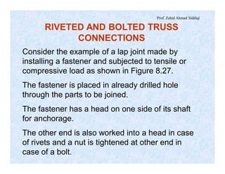
- 1. Prof. Zahid Ahmad Siddiqi Consider the example of a lap joint made by installing a fastener and subjected to tensile or compressive load as shown in Figure 8.27. The fastener is placed in already drilled hole through the parts to be joined. The fastener has a head on one side of its shaft for anchorage. The other end is also worked into a head in case of rivets and a nut is tightened at other end in case of a bolt. RIVETED AND BOLTED TRUSS CONNECTIONS
- 2. Prof. Zahid Ahmad Siddiqi T T TT Failure Plane Shaft of Fastener Grip Head of Fastener Bearing Stresses Figure 8.27.Lap Joint Using a Single Rivet.
- 3. Prof. Zahid Ahmad Siddiqi The bolts may be arbitrarily tightened called snug tight bolts. Or they may be subjected to a predefined torque producing pre-tension in the bolts and compression on the joining plates known as high strength bolts. The distance between the two heads after placing of the fasteners is called grip of the fastener. A bolted joint in which the slip resistance of the connection is also utilized is called Slip Critical Joint.
- 4. Prof. Zahid Ahmad Siddiqi The minimum bolt pretension for high strength bolts is given in Table 8.4. The pretension is measured by the turn-of-nut method, direct tension indicator, calibrated wrench or alternative design bolt. Bolt Size, d (mm) A325M Bolts Pretension (kN) A490M Bolts Pretension (kN) Standard Hole Dia (mm) M15 80 100 17 M18 115 145 20 M20 142 179 22 M22 176 221 24 M25 225 282 28 M28 286 358 31 M30 326 408 33 M35 448 562 38 > M35 - - d + 3
- 5. Prof. Zahid Ahmad Siddiqi The rivets used for structural purposes are driven and installed in red hot state and are therefore known as hot driven rivets. Once the head is made on both sides of the rivet in red-hot state and the rivet is then allowed to cool, compression on the parts to be joined is produced. This is required for close packing of members at the joint and to avoid chattering of joints. Further, by using hot rivets, it becomes easy to make head by hammering.
- 6. Prof. Zahid Ahmad Siddiqi ASTM Specification A502 deals with these types of rivets and the qualities of these rivets are defined as Grade1, Grade 2 and Grade 3 rivets. Grade 1 rivets are having lesser strength and their corrosion resistance is also of ordinary level. Grades 2 and 3 rivets are used for higher strength and better corrosion resistance. The tensile and shear strengths of some common types of rivets and bolts are given in Table 8.5.
- 7. Prof. Zahid Ahmad Siddiqi Table 8.5. LRFD Nominal Tensile and Shearing Strengths for Rivets and Bolts. S.# Fastener Type Tensile Strength (MPa) ft Shearing Strength in Bearing Type Connections (MPa) fv 1- A502, grade 1, hot driven rivets. 310 0.75 172 0.75 2- A502, grade 2 or 3, hot driven rivets. 414 0.75 228 0.75 3- A307 bolts. 310 0.75 165 0.75 4- A325M bolts (Fu = 825 MPa) when threads are not excluded from shear planes. 0.75 Fu = 620 0.75 0.40 Fu = 330 0.75 5- A490M bolts (Fu = 1035 MPa) when threads are not excluded from shear planes. 0.75 Fu = 780 0.75 0.40 Fu = 414 0.75
- 8. Prof. Zahid Ahmad Siddiqi TYPE OF STRESSES IN FASTENERS When the lap type connection of Figure 8.27 is subjected to tension or compression, the fastener is subjected to shear at a cross-section lying at the interface of the two parts. This cross-section at which different layers of the fastener try to slide against each other and failure can occur here is called a shear failure plane. The cross-sectional area resisting shear in case of rivets will be p/4 d2 where d is the diameter of the rivets. However, in case of a bolt, there are two possibilities.
- 9. Prof. Zahid Ahmad Siddiqi Bolt will have more strength if failure plane lies in unthreaded portion and less strength if failure plane lies within the threads. The effective area of cross-section resisting shear in the later case will be less, considered equal to approximately 75% of the total area without threads, due to grooves within the threads. However, adjustment for this reduction is made in the strength and then area calculated on the basis of outer diameter is used to evaluate the strength.
- 10. Prof. Zahid Ahmad Siddiqi Because the fastener and plate are not fully joined with each other, the forces from the fasteners are transferred to the plates by bearing stresses in the plate material surrounding the bolt on one side as shown in Figure 8.27. Bearing Stresses Bearing stresses are very high but local compressive stresses produced when two surfaces abut each other and transfer load. If sufficient material is available around the zone of high bearing stresses, these stresses quickly spread over a greater region reducing the intensity.
- 11. Prof. Zahid Ahmad Siddiqi The locally stressed material is confined in nature. For this reason and for the reason that these local compressive stresses cannot produce fracture and buckling, stresses up to 3.0 times the ultimate tensile strength of plate material (3.0 Fu) may be allowed at nominal strength level. According to AISC, bearing strength must be checked for both bearing type and slip critical connections.
- 12. Prof. Zahid Ahmad Siddiqi (a) When deformation at bolt hole due to service loads is a consideration: Nominal bearing strength, Rn = 1.2 Lc t Fu £ 2.4 d t Fu where Lc = clear edge distance or clear spacing between bolts t = thickness of connected material f = 0.75 and W = 2.00
- 13. Prof. Zahid Ahmad Siddiqi (b) When deformation at bolt hole due to service loads is not a consideration: Nominal bearing strength, Rn = 1.5 Lc t Fu £ 3.0 d t Fu f = 0.75 and W = 2.00 Shear Stresses When two plates of a lap joint are pulled in opposite direction as in Figure 8.28, only one failure plane is produced and the fastener strength is determined by one cross-section of the fastener.
- 14. Prof. Zahid Ahmad Siddiqi T T Figure 8.28. Rivet Under Single Shear. T T/2 T/2 Figure 8.29. Rivet Under Double Shear.
- 15. Prof. Zahid Ahmad Siddiqi This type of shear is called single shear denoted by “1s” in calculations. In case of the simplest half part of butt joint (Figure 8.29), three plates are trying to move relative to each other. Two failure planes are produced and two cross-sections resist the applied load. The shear strength becomes double as that of single shear for same material and diameter of the fastener. In other words, the applied force is divided at greater number of cross-sections.
- 16. Prof. Zahid Ahmad Siddiqi This type of shear is called double shear denoted by “2s” in calculations. In general, number of shear planes is always equal to one less than the number of moving plates. Number of shears = Number of moving plates – 1 For example, the fastener in Figure 8.30 is subjected to 4- times shear because of five moving plates. It should be noted that any adjacent plates, which cannot move in opposite direction, are counted as a single unit in the above formula.
- 17. Prof. Zahid Ahmad Siddiqi T/2 T/2 Figure 8.30. Rivet Under 4-Times Shear. T/3 T/3 T/3
- 18. Prof. Zahid Ahmad Siddiqi The four plates in Figure 8.31 are subjected to single shear. Figure 8.31. Single Shear In Rivet Joining Four Plates. BEARING TYPE CONNECTIONS When the loads to be transferred are larger than the frictional resistance caused by tightening the bolts, the members slip a little on each other putting the fasteners in shear and the surrounding member in bearing.
- 19. Prof. Zahid Ahmad Siddiqi The resulting type of connections are called bearing connections. EFFECTIVE BEARING AREA According to AISC, the effective bearing area of bolts, threaded parts and rivets shall be the diameter of such fasteners multiplied by the length of bearing: Rn = 2.4 Fu ´ d ´ t when Lc ³ 2d otherwise Rn = 1.2 Fu ´ Lc ´ t (In case deformation at service load is a design consideration)
- 20. Prof. Zahid Ahmad Siddiqi where f = 0.75 (LRFD) and W = 2.00 t = smaller thickness of plate, subjected to following conditions: a) edge distance not less than 1.5 d, b) c/c distance between fasteners not less than 3d, and, c) 2 or more fasteners in the line of force.
- 21. Prof. Zahid Ahmad Siddiqi RIVET AND BOLT VALUE The load in kN which a single rivet can carry is called its rivet value (Ru). The rivet value is smaller of rivet shear strength and the plate bearing strength. Ru = lesser of fRns and fRn
- 22. Prof. Zahid Ahmad Siddiqi Rivet/bolt shear strength, f Rns = resistance factor ´ rivet shear strength ´ area in shear ´ number of shear planes = f ´ rivet shear strength ´p/4 d2 ´ n Rivet/bolt plate bearing strength, fRn = resistance factor ´ bearing strength ´ area in bearing = 0.75´ 2.4Fu´ d´t when Lc ³ 2d where d is the outer or nominal diameter of the rivet or bolt.
- 23. Prof. Zahid Ahmad Siddiqi Rivet Value In Case Of Lap Joint Typical example of a lap joint is the connection of a single angle section (thickness = ta) with the gusset plate (thickness = tg), as shown in Figure 8.32. Because of two moving plates, the rivets will be subjected to single shear (1s). Most commonly, the angle thickness is lesser than the gusset plate thickness. Using A502 Grade-2 rivets, the rivet value may be calculated as follows:
- 24. Prof. Zahid Ahmad Siddiqi tg ta ta £ tg T T Ru = lesser of 1) shear strength of rivet in single shear fRIS = 0.65´330´p/4 d2´1 / 1000 = 0.168 d2 (kN)
- 25. Prof. Zahid Ahmad Siddiqi 2) strength of rivet based upon its bearing on plate. fRn = 0.75 ´ 2.4 ´ 400 ´ d ´ ta = 0.72 d ta (kN) when Lc ³ 2d for A36 steel Rivet Value In Case Of Half Butt Joint Typical example of a half butt joint is the connection of double angle section with the gusset plate (Figure 8.33).
- 26. Prof. Zahid Ahmad Siddiqi The rivets are subjected to double shear. For bearing, the total load is either resisted by the thickness of gusset plate (tg) or two times the angle thickness (2ta), usually tg is lesser than 2ta. Using A502 Grade 2 rivets, the rivet value is evaluated as under: Ru =lesser of 1) fR2s = 0.65´330´p/4 d2 ´2 / 1000 = 0.337d2 (kN) 2) fRn = 0.75 ´ 2.4 ´ 400 ´d ´ tg = 0.72 d tg (kN) when Lc ³ 2d
- 27. Prof. Zahid Ahmad Siddiqi T/2 T/2 T REQUIRED CLEARANCES Minimum Edge Distance The minimum distance from center of rivet to the edge should preferably be not less than 1.5d.
- 28. Prof. Zahid Ahmad Siddiqi If this distance is not maintained, detailed formulas given in the chapter on tension members and in another article in this chapter are to be satisfied. The distance should be kept equal to 2.5d + 2 (mm) to obtain bearing strength equal to 2.4 Fu. Minimum Spacing Of Fasteners The minimum longitudinal and transverse spacing of fasteners (pitch or gage) shall preferably be not less than 3d.
- 29. Prof. Zahid Ahmad Siddiqi This is to avoid stress concentrations and to make drilling of holes and tightening of bolts easier. For spacing lesser than 3d, formulas given earlier for tension members must be checked. Further, to improve bearing strength of bolts, it is better to slightly increase this spacing to a value of 3d+3 mm, which given clear spacing (Lc) equal to 2d.
- 30. Prof. Zahid Ahmad Siddiqi Maximum Edge Distance And Spacing The maximum distance from the center of fastener to the nearest edge of parts shall be lesser of 12 t and 150 mm, where ‘t’ is the smaller thickness of the connected parts. The pitch of fasteners is kept lesser than the following maximum value to prevent corrosion of loose plates from inside of the over lap: pmax = lesser of 305 mm and 24 t for painted and non-corrosive steels pmax = lesser of 180 mm and 14 t for unpainted steels
- 31. Prof. Zahid Ahmad Siddiqi where t = thickness of thinner part joined DIAMETER OF FASTENER Minimum diameter of rivets and bolts for trusses and other building structures is 15 mm. The usual size of rivets or bolts used for specific purposes is as under: In buildings: 15, 18, 20 mm In bridges: 22, 25, 28 mm In warehouses and towers: 30, 32, 35 mm
- 32. Prof. Zahid Ahmad Siddiqi Preferable diameter of fastener is usually taken by the following expression: d = t6 rounded to the nearest available size where t = thickness of thicker part, mm Economical diameter of fastener means the diameter of a rivet or bolt for which the shearing strength is theoretically equal to bearing strength of the parts to be joined. However, for most practical cases, it becomes difficult to use this diameter.
- 33. Prof. Zahid Ahmad Siddiqi For A 502 Grade 2 rivets connecting double angles section with the gusset plate both of A36 steel, 0.65 ´ p/4 d2 ´ 330´2 = 0.75 ´ 2.4 ´ 400 ´ d ´ tG Economical diameter, d = 2.14 tG (rounded to nearest available size) The grip of a rivet shall not exceed 8 times the diameter of the holes in any case.
- 34. Prof. Zahid Ahmad Siddiqi ADVANTAGES OF BOLTS OVER RIVETS 1. Smaller working crews are required as compared with riveting. The efficiency of construction is approximately double per person. 2. Less high strength bolts may be needed as compared with rivets. 3. The experience required to properly install bolts is significantly lesser than is necessary for welded and riveted connections. 4. Less noise is produced during construction as compared with riveting.
- 35. Prof. Zahid Ahmad Siddiqi 5. Cheaper equipment is used to make bolted connections compared with welded or riveted connections. 6. Fire in case of welding and hot material in case of rivets is avoided. 7. Fatigue strength of fully tight high strength bolts is greater than that of rivets. 8. Future changes are very easy with bolts.
- 36. Prof. Zahid Ahmad Siddiqi ROCEDURE FOR DESIGN OF RIVETED TRUSS CONNECTIONS 1. Find design capacity of the member, ftTn or fcPn. 2. Compare calculated factored force in the member with the given percentage of the member capacity (usually not less than 50%) and select the design force for connection as follows: Fu = larger of 1) factored force 2) a %age of ft Tn or fcPn
- 37. Prof. Zahid Ahmad Siddiqi 3. For un-spliced top and bottom chord members, the difference of forces in the adjacent panels is to be used in a way to get the maximum possible answer. 4. Decide the rivet diameter which should remain same throughout the truss. 5. Find rivet value (Ru) according to single or double shear. 6. Find number of rivets (N) as follows: N = (rounded to higher whole number) u u R F
- 38. Prof. Zahid Ahmad Siddiqi 7. For better joint efficiency and lesser stress concentrations, a minimum of 3 rivets is preferred. Cost of few extra rivets is much lesser than extra cost spent on the member for lesser joint efficiency. 8. The length of joint should not be excessive. If numbers of rivets are more than approximately five, arrange them in more rows. However, the connection length of a tension member (l) must be large enough to give better joint efficiency. For U = 0.9, lpref = 10 = distance between the centroid of element and the interface surface. x x
- 39. Prof. Zahid Ahmad Siddiqi 9. Decide the spacing and edge distances of rivets depending on minimum and maximum requirements. In transverse direction, place the rivets along standard gages. 10. Check block-tearing strength as discussed earlier for welded connections. 11. Make a neat sketch to show the results. 12. Verify that net area and U, in case of tension members, are greater than or equal to the values taken during the member design.
- 40. Prof. Zahid Ahmad Siddiqi Example 8.3: Design rivets for the connection shown in Figure 8.34 with the condition that each member should be able to develop at least 50% of the effective strength. Use A502 Grade 2 hot driven rivets. The magnitudes of forces are all factored. Gusset plate is 10 mm thick. 45°45° L 76 ´ 64 ´ 9.5 L 76 ´ 64 ´ 9.5 2Ls 102 ´ 102 ´ 9.5 F2 = 350 kN(T) F1 = 168 kN(T) F3 = 70 kN(C) Length = 1.0 m F4 = 210 kN(T)
- 41. Prof. Zahid Ahmad Siddiqi 50% capacity of L76´64´9.5 in compression For compression members, double angle sections should be preferred. However, the capacity calculated based on the assumption of concentric loading for single angle section will be on safer side for the connection. zr Kl 3.13 10001´ A = 1240 mm2 = @ 76 fcFcr = 165.66 MPa 0.5fcPn = ½ ´ 165.66 ´ 1240 / 1000 @ 102.7 kN
- 42. Prof. Zahid Ahmad Siddiqi 50% capacity of L76´64´9.5 in tension The calculation may be based on the assumption that An is equal to 85% of Ag in the absence of accurate value of net area and the value of U may be taken equal to 0.85. Both of these assumptions are to be checked after the connection design. A = 1240 mm2 0.5ft Tn = lesser of 1. 1/2 ´ 0.9 ´ 250 ´1240/1000 = 139.5 kN 2. 1/2 ´0.75´400´0.85´0.80´1240/1000 = 126.5 kN = 126.5 kN
- 43. Prof. Zahid Ahmad Siddiqi 50% Capacity of 2Ls102´102´9.5 in tension Area of one angle = 1850 mm2 Using the same assumptions as above: 0.5ftTn = lesser of 1. ½ ´ 0.9´250´2´1850/1000 = 416.3 kN 2. ½ ´ 0.75´400´0.85´0.80´2´1850/1000 = 377.4 kN = 377.4 kN
- 44. Prof. Zahid Ahmad Siddiqi Fu for members 1and 2= larger of 1) (larger of F2 and its 0.5ftTn) – F1 = 377.4 – 168 = 209.4 kN 2) 210 cos45°+ 102.7 cos45° = 221.1 kN = 221.1 kN Fu for member 3 = larger of 1) 70 kN 2) 102.7 kN = 102.7 kN
- 45. Prof. Zahid Ahmad Siddiqi Fu for member 4 = larger of 1) 210 kN 2) 126.5 kN = 210 kN t6 106d = = = 18.97 mm say 18 mm Rivet Values on the next slide
- 46. Prof. Zahid Ahmad Siddiqi L76´64´9.5, assuming Lc ³ 2d, Ru = lesser of fR1S = 0.75 ´ 228 ´ p/4(18)2 ´ 1/1000 = 43.51 kN fRn = 0.75 ´ 2.4 ´ 400 ´18 ´ 9.5/1000 = 123.12 kN = 43.51 kN 2Ls 102´102´9.5, assuming Lc ³ 2d, Ru = lesser of fR2S = 0.75 ´ 228 ´ p/4 (18)2 ´ 2/1000 = 87.03 kN fRn = 0.75 ´ 2.4 ´ 400 ´ 18 ´ 10.0/1000 = 129.60 kN = 87.03 kN
- 47. Prof. Zahid Ahmad Siddiqi Number of rivets for members 1and 2 = 03.87 1.221 = 2.54 say 3 Number of rivets for member 3 = 51.43 7.102 = 2.36 say 3 Number of rivets for member 4 = 51.43 210 = 4.83 say 5 Minimum edge distance to provide Lc = 2d: = 2.5 d + 2 = 2.5 ´ 18 + 2 = 47 mm
- 48. Prof. Zahid Ahmad Siddiqi Maximum edge distance = lesser of 1) 12 t = 12 ´ 9.5 = 114 mm 2) 150 mm = 114 mLet edge distance = 50 mm for inclined members Minimum pitch = 3d = 3 ´ 18 = 54 mm Maximum pitch, considering unpainted surfaces, = lesser of 1) 180 mm 2) 14 t = 133 mm = 133 mm
- 49. Prof. Zahid Ahmad Siddiqi x x Let pitch= 60 mm for diagonal members and 130 mm for bottom chord members. for L76´64´9.5 = 17.9 mm For U = 0.80, lpref = 5.0 = 89.5 mm Connection length for L76´64´9.5 in tension = 4 ´ 60 = 240 mm > 89.5 mm OK Provide all rivets in a single line along the standard gage line. The rivets on bottom chord are spread closer to maximum value of pitch to satisfy the shape of gusset plate.
- 50. Prof. Zahid Ahmad Siddiqi 44 44 32 32 50 60 60 60 50 60 60 50 38 64 130 130 50 Between 50 and 114 Between 50 and 114 60 44 44 32 32 50 60 60 60 50 60 60 50 38 64 130 130 50 Between 50 and 114 Between 50 and 114 60
- 51. Prof. Zahid Ahmad Siddiqi Block shear may be checked by a procedure discussed earlier. The readers are required to perform this check. To verify that An ³ 0.85 Ag and U = 0.80 are left as exercise for the readers. DESIGN OF LOADED TRUSS JOINTS Spliced joint is a joint where the upper or lower chord is discontinuous and it is designed like an ordinary joint even if load is acting on it. The loaded joint with continuous upper or lower chord member is called un-spliced loaded joint.
- 52. Prof. Zahid Ahmad Siddiqi This is also designed as for an unloaded joint. However, the transverse component of the load is to be transferred through the member to the gusset plate, and this force is not considered in the truss analysis for the axial forces (Figure 8.36). Transverse load component (V) acts on top chord at the joint of Figure and is to be transferred to gusset plate through the rivets. Hence, resultant force on rivets R¢u is to be calculated as follows:
- 53. Prof. Zahid Ahmad Siddiqi F1 F2 V P F4 F5 F3 q4 q3 q F1 F2 V P F4 F5 F3 q4 q3 q
- 54. Prof. Zahid Ahmad Siddiqi R¢u = resultant force on each rivet N = number of rivets provided for the top chord Fu = design force for the connection When R¢u = 22 ÷ ø ö ç è æ +÷ ø ö ç è æ N V N Fu If R¢u > Ru: 1. The number of rivets is increased. 2. Diameter of the rivets is increased. 3. Lug angle may also be used. £ Ru OK
- 55. Prof. Zahid Ahmad Siddiqi BOLTS SUBJECTED TO ECCENTRIC SHEAR Eccentrically loaded bolt/rivet groups are subjected to direct shears and torque as shown in Figure 8.54. In a truss, if the center of gravity of a member is not in line with the center of gravity of the bolts at its end connections, moments are produced. Eccentricity is quite obvious in a bracket and is also present in shear connection of beam with a column.
- 56. Prof. Zahid Ahmad Siddiqi In Figure 8.55, a typical group of four bolts is shown with the load acting at some eccentricity, e, from the centroid of the bolt system. This load may be transferred to the centroid but it will then be accompanied by a torque (T = P ´ e), as shown in Figure 8.56. Both Figures 8.55 and 8.56 are equivalent as far as the structural behavior is concerned.
- 57. Prof. Zahid Ahmad Siddiqi a) Bracket b) Shear Connection of Beam With Column a) Bracket b) Shear Connection of Beam With Column
- 58. Prof. Zahid Ahmad Siddiqi c.g. c.g. e P P Figure 8.55. Typical Group of Bolts/Rivets Subjected to Eccentric Shear. Figure 8.56. Eccentric Shear On a Bolt/Rivet Group Converted to Shear and Torque at the Centroid. 12 3 4 Tu = P ´ eGroup of Bolts c.g. c.g. e P P Figure 8.55. Typical Group of Bolts/Rivets Subjected to Eccentric Shear. Figure 8.56. Eccentric Shear On a Bolt/Rivet Group Converted to Shear and Torque at the Centroid. 12 3 4 Tu = P ´ eGroup of Bolts
- 59. Prof. Zahid Ahmad Siddiqi The bolts shown in Figure 8.56 are subjected to a downward force (P / N) in each fastener called direct shear force plus the shear force due to the torque called eccentric shear. The force in each fastener (Fi) due to the torque and distance of each fastener (di) from the centroid are shown in Figure 8.57.
- 60. Prof. Zahid Ahmad Siddiqi F1 F2 F3 F4 e P d1 d2 d3 d4 c.g . F1 F2 F3 F4 e P d1 d2 d3 d4 c.g .
- 61. Prof. Zahid Ahmad Siddiqi The torque causes the plate to rotate about the centroid of the bolt connection keeping the amount of rotation or strain at a particular bolt being proportional to its distance from the centroid. These strains produce stresses and forces Fi in the bolts. Greater is the distance of a fastener from the centroid, more will be the force. Further, force in each fastener will be perpendicular to the distance vector between the centroid and that fastener. These eccentric forces will produce same turning effect as that of the applied torque (clockwise or counterclockwise).
- 62. Prof. Zahid Ahmad Siddiqi 1 1 d F 2 2 d F 3 3 d F 4 4 d F Magnitude Of Eccentric Shear From Figure 8.57, Tu =P ´ e = F1 d1 + F2 d2 + F3 d3 + F4 d4 I For force to be proportional to the distance, we can write: = = = 1 2 11 d dF 2 2 22 d dF 3 2 33 d dF 4 2 44 d dF Equation I can be written as: Tu = +++ = ( )2 4 2 3 2 2 2 1 1 1 dddd d F +++ II
- 63. Prof. Zahid Ahmad Siddiqi Þ Tu = å 2 1 1 d d F Þ F1 = å 2 1 d dTu III å 2 2 d dTu å 2 3 d dTu å 2 4 d dTu Similarly F2 = , F3 = , F4 = IV Each force Fi is perpendicular to the line drawn from the centroid to the particular bolt. It is usually more convenient to break these down into vertical and horizontal components (Figure 8.58).
- 64. Prof. Zahid Ahmad Siddiqi The horizontal and vertical components of the distance d1 are represented by h1 and n1, respectively, and the horizontal and vertical components of force F1 are represented by H1 and V1, respectively. q1 V1 H1 h1 v1 d1 c.g . q1F1 q1 V1 H1 h1 v1 d1 c.g . q1F1
- 65. Prof. Zahid Ahmad Siddiqi 1 1 1 1 d h F V = 1 1 d h From Figure 8.58: or V1 = F1 Substituting the value of F1 from above: å 2 1 d hTu 1 1 1 1 d v F H = 1 1 d v å 2 1 d vTu V1 = Similarly, Þ H1 = F1 Þ H1 = VI V
- 66. Prof. Zahid Ahmad Siddiqi å 2 d vT iu å 2 d hT iu In general: Hi = and Vi = VII 2 1d 2 2d 2 nd 2 ih 2 in Sd2 for a rivet system may be calculated as S + + - - - + or as S + S . The total shear for each fastener is calculated as the sum of eccentric shear and direct shear. The magnitude of this total shear will vary for each fastener. The fastener which has the maximum shear is called the most heavily stressed fastener and is to be located before further calculations.
- 67. Prof. Zahid Ahmad Siddiqi One way of locating this critical rivet is to find resultant shear for each fastener and then finding the maximum value. However, this procedure may require lengthy calculations. A visual observation is used to reduce such extra work. The fasteners having the maximum distance from the centroid (corner fasteners) are expected to be more critical.
- 68. Prof. Zahid Ahmad Siddiqi Further, out of these, whichever has both horizontal and vertical components of direct and eccentric shears in the same direction is expected to be the most critical. If there is any doubt about the condition of this fastener by visual observation, all the competing fasteners must by investigated by calculating the resultant shear. The procedure is clear in Example 8.6.
- 69. Prof. Zahid Ahmad Siddiqi Required Number of Fasteners When the eccentricity of the load on a bolt group is less than about 60 mm, it is neglected. For a shear force of Pu (kN) and a torque of Tu (kN-m), the number of A502 Grade 2 rivets (N) of 15 mm diameter may be approximately determined as under: N = 000,1570 uu TP +
- 70. Prof. Zahid Ahmad Siddiqi Example 8.6: Find the diameter of rivets for the bracket shown in Figure 8. 59. P=800kN (factored force) 10050 100 250 50 75 100 125 10 7 4 1 11 8 5 2 12 6 9 3 20° c.g. P=800kN (factored force) 10050 100 250 50 75 100 125 10 7 4 1 11 8 5 2 12 6 9 3 20° c.g.
- 71. Prof. Zahid Ahmad Siddiqi Solution: Let y = distance from top of bracket to centroid of the rivet system, and A = area of a single rivet. Taking moment of the resultant rivet area about the top edge of bracket (12A ´ y) and equating it to the sum of moments of the individual areas about the same edge, y may be evaluated. y = ( ) ( ) ( ) ( ) A12 350A3225A3125A350A3 +++ = 187.5 mm
- 72. Prof. Zahid Ahmad Siddiqi N Px 12 8.751 Rivet 10 is expected to be critical as horizontal and vertical forces due to moment and applied load add into one another. However, rivet-1 may also be investigated. Horizontal component of load = Px = 800 ´ cos20° = 751.8 kN Vertical component of load = Py = 800 ´ sin20° =273.6 kN Horizontal force on each rivet = = = 62.65 kN
- 73. Prof. Zahid Ahmad Siddiqi N Py 12 6.273 Vertical force on each rivet = = Torque at centroid Tu = 751.8 ´ 187.5 (counterclockwise) - 273.6 ´ 350 (clockwise) = 45,202.5 kN-mm (counterclockwise) = 22.80 kN d1 = 22 5.162100 + = 190.8 mm = d3 d2 = 162.5 mm
- 74. Prof. Zahid Ahmad Siddiqi 22 5.37100 + 22 5.62100 + 22 5.137100 + d4 = = 106.8 mm = d6 d5 = 37.5 mm d7 = = 117.9 mm = d9 d8 = 62.5 mm d10 = = 170.0 mm = d12 d11 = 137.5 mm Sd2 = 231,848 mm2
- 75. Prof. Zahid Ahmad Siddiqi Rivet Value Ru = 0.75 ´ p/4d2 ´ 228 / 1000 = 0.1343 d2 å 2 10 d vTu 848231 5137520245 , .., ´ å 2 10 d hTu 848231 100520245 , ., ´ Shear For Rivet 10 Eccentric Shear H10 = = = 26.81 kN V10 = = = 19.50 kN
- 76. Prof. Zahid Ahmad Siddiqi Total horizontal force = 62.65 + 26.81 = 89.46 kN Total vertical force = 22.80 + 19.50 = 42.30 kN Resultant force = 22 30424689 .. + Rivet Diameter The rivet diameter may be found by equating the rivet value to the shear force in the most heavily stressed rivet, as under: = 98.96 kN
- 77. Prof. Zahid Ahmad Siddiqi 0.1343 d2 = 98.96 d = 27.15 mm Use 28 mm diameter rivets Check Fastener Bearing Strength This check is performed if the plate thicknesses are given. The bolt bearing value must be greater than its shear value.