
Empfohlen
Weitere ähnliche Inhalte
Was ist angesagt?
Was ist angesagt? (20)
Ähnlich wie Equivalent circuit of Induction Motor
Ähnlich wie Equivalent circuit of Induction Motor (20)
Mehr von Citharthan Durairaj
Mehr von Citharthan Durairaj (16)
Kürzlich hochgeladen
Kürzlich hochgeladen (20)
Equivalent circuit of Induction Motor
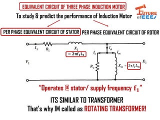
- 1. EQUIVALENT CIRCUIT OF THREE PHASE INDUCTION MOTOR PER PHASE EQUIVALENT CIRCUIT OF STATOR PER PHASE EQUIVALENT CIRCUIT OF ROTOR To study & predict the performance of Induction Motor ITS SIMILAR TO TRANSFORMER That’s why IM called as ROTATING TRANSFORMER! = 𝟐𝛑𝐟 𝟏 𝐋 𝟏 “Operates @ stator/ supply frequency 𝐟 𝟏”
- 2. PER PHASE EQUIVALENT CIRCUIT OF ROTOR Slip rpm S* Ns= Ns- N Rotor circuit frequency 𝐟 𝟐 = 𝐒𝐟 𝟏 So, frequency dependent parameters such as reactance and EMF will be 𝐒𝐄 𝟐 & 𝐒𝐗 𝟐 S S = 𝟐𝛑𝐟 𝟐 𝐋 𝟐 We Cant Combine Stator & rotor equivalent circuit directly! Problem 1 : Stator & rotor circuit are operating @ different frequency Problem 2 : Air-gap is between the stator and rotor “Operates @ rotor frequency 𝐟 𝟐”
- 3. To overcome the problem 1 𝐈2 = 𝐒𝐄2 𝐑2 2 + ൯ሺ 𝐒𝐗2 2 𝐈2 = 𝐒𝐄2 𝐒 𝐑2 𝐒 2 + 𝐗2 2 “Operates @ rotor frequency 𝐟 𝟐” “Operates @ stator frequency 𝐟 𝟏”
- 4. To overcome the problem 2 (Speaker resistance referred to the primary side) Air gap Air gap 𝐑 𝟐 ′ = 𝐚 𝟐 ∗ 𝐑 𝟐 𝐈 = 𝟏𝟎 𝟏 + 𝟏 = 𝟓 𝐀𝐦𝐩𝐬 𝐑 𝟐 ′ = 𝐍 𝟏 𝐍 𝟐 𝟐 ∗ 𝐑 𝟐 ⇒ 𝟏 𝟑 ∗ 𝟗 ⇒ 𝟏
- 5. PER PHASE TOTAL EQUIVALENT CIRCUIT OF IM REFERRED TO STATOR SIDE Air gap (a = S to R turns ratio) ሺ𝐑 𝟐 ′ = 𝐚 𝟐 𝐑 𝟐)
- 6. The air-gap power associated with the equivalent circuit is 𝐏𝐚𝐠 = 𝐈 𝟐 𝟐 𝐑 𝟐 ′ 𝐒 𝐏𝐚𝐠 = 𝐈2 2 𝐑2 ′ + 𝐑2 ′ 𝐒 − 𝐑2 ′ 𝐏𝐚𝐠 = 𝐈 𝟐 𝟐 𝐑 𝟐 ′ + 𝐑 𝟐 ′ 𝐒 ሺ𝟏 − 𝐒) Rotor copper loss Pcu2 = 𝐈 𝟐 𝟐 𝐑 𝟐 ′ Mechanical Power Pmech = 𝐈 𝟐 𝟐 𝐑 𝟐 ′ 𝐒 (1-S) Power Flow Diagram of IM 𝐏𝐚𝐠 Pcu2 Pmech P electric Pcore + Pcu1
- 7. Ratio of Air-gap power , Rotor copper loss & Mechanical power developed Pag : Pcu2 : Pmech = 1 : S : (1-S) 𝐈 𝟐 𝟐 𝐑 𝟐 ′ 𝐒 : 𝐈 𝟐 𝟐 𝐑 𝟐 ′ : 𝐈 𝟐 𝟐 𝐑 𝟐 ′ 𝐒 (1-S) Dividing By 𝐈 𝟐 𝟐 𝐑 𝟐 ′ 𝐒 1 : S : (1-S) Pag : Pcu2 : Pmech Important Note By operating at low slip rotor copper loss can be minimized & mechanical power can be increased or in other words Efficiency of IM will increase
- 8. IMPORTANT POINTS TO REMEMBER IN TORQUE- SLIP CHARACTERISTICS • Torque is directly proportional in low slip region of IM • Torque is inversely proportional in high slip region of IM • Low slip region is called stable region • Maximum torque obtained is called pull out torque in IM • The slip @ which the pullout torque occurs is called critical slip • Critical slip = R2/X2 • By increasing the resistance in rotor it is possible to increase the starting torque (This is possible only in slip ring IM!!). Maximum torque is irrespective to Rotor resistance!
- 9. IMPORTANT POINTS TO REMEMBER IN EQUIVALENT CIRCUIT OF AN INDUCTION MOTOR • Equivalent circuit of IM is used to study and predict the performance of IM • From solving the equivalent circuit we understand that, from the total air-gap power, a fraction of “slip power” S is dissipated in the resistance of the rotor circuit (rotor copper loss) • A fraction of (1-S) is converted into mechanical power • So we understand the lower the slip – higher the mechanical power and lesser the rotor copper loss or higher efficiency. • All Equivalent circuit parameters (E, I, R, X) can be found from No load test and Blocked rotor test (Document given in the description!)