SlideShare ist ein Scribd-Unternehmen logo
1 von 40
Downloaden Sie, um offline zu lesen
Improved Off Road Chassis
ME EN 4010 – Spring 2014 Final Report
Project Team:
Chris Pell, Matt Baker, Todd McGraw, Nick Child, Alex Welton, Steve Bell
Project Advisor:
Dr. K. Larry DeVries, Ph.D. – Distinguished Professor
April 2014
ME EN 4010 Spring 2014 April 2014
Improved Off Road Chassis Final Report
i
Table of Contents
Table of Contents............................................................................................................................. i
1. Front Matter ............................................................................................................................. 1
1.1. Executive Summary.......................................................................................................... 1
1.1.1. Introduction................................................................................................................ 1
1.1.2. Key Focus Areas........................................................................................................ 1
1.1.3. Conclusion ................................................................................................................. 2
1.2. Acknowledgements........................................................................................................... 3
1.2.1. Student Design Team................................................................................................. 3
1.2.2. Teaching Team........................................................................................................... 4
1.2.3. Corporate Sponsors.................................................................................................... 5
1.2.4. Additional Acknowledgements.................................................................................. 5
2. Design Requirements............................................................................................................... 5
2.1. Overview........................................................................................................................... 5
2.2. Improved Repairs.............................................................................................................. 5
2.2.1. Faster and Cheaper Repairs ....................................................................................... 6
2.2.2. Easier Repairs ............................................................................................................ 6
2.3. Rigidity ............................................................................................................................. 6
2.3.1. Increase Energy Transferred to Shock Absorbers ..................................................... 6
2.3.2. Allow for Adjustments to Suspension ....................................................................... 6
2.3.3. Prevent Misalignment ................................................................................................ 6
2.3.4. Reduce Unwanted Noise............................................................................................ 7
2.4. Increased Customization................................................................................................... 7
2.4.1. Increased Rigidity...................................................................................................... 8
2.4.2. Decreased Weight ...................................................................................................... 8
2.4.3. Decreased Cost........................................................................................................... 9
2.5. Decreased Need for Welding............................................................................................ 9
ME EN 4010 Spring 2014 April 2014
Improved Off Road Chassis Final Report
ii
2.5.1. No Heat Damage........................................................................................................ 9
2.5.2. More Consistent Performance.................................................................................... 9
2.6. Widely Applicable Technology........................................................................................ 9
3. Design Specifications............................................................................................................... 9
3.1. Overview........................................................................................................................... 9
3.2. Improved Repairs............................................................................................................ 10
3.2.1. Ease of Repair.......................................................................................................... 10
3.2.2. Time of Repair ......................................................................................................... 10
3.2.3. Cost of Repair .......................................................................................................... 11
3.3. Rigidity ........................................................................................................................... 11
3.3.1. Amount of Stress...................................................................................................... 11
3.3.2. Linear Displacement ................................................................................................ 12
3.3.3. Alignment of Parts ................................................................................................... 12
3.4. Material Customization................................................................................................... 12
3.4.1. Use of Diverse Materials ......................................................................................... 12
3.4.2. Cost of Frame Manufacturing.................................................................................. 13
3.4.3. Weight of Frame ...................................................................................................... 13
3.5. Decreased Welding......................................................................................................... 13
3.6. Widely Applicable Technology...................................................................................... 13
3.6.1. Technology is Widely Accessible............................................................................ 14
3.6.2. Technology Instills a Sense of Pride in Machine..................................................... 14
4. Conceptual Design................................................................................................................. 14
4.1. Initial Concepts ............................................................................................................... 14
4.1.1. Lapped Joint............................................................................................................. 14
4.1.2. Bonded Sleeve Joint................................................................................................. 15
4.1.3. Welded Sleeve Joint................................................................................................. 15
4.2. Adhesive Selection.......................................................................................................... 15
ME EN 4010 Spring 2014 April 2014
Improved Off Road Chassis Final Report
iii
4.3. Product Architecture ....................................................................................................... 16
4.3.1. High-Level System Design...................................................................................... 16
4.3.2. Detailed Subsystems ................................................................................................ 17
5. Final Design........................................................................................................................... 17
6. Performance Verification....................................................................................................... 19
6.1.1. Physical Sleeve Joint Prototypes ............................................................................. 20
6.1.2. Analytical Modeling ................................................................................................ 22
6.1.3. Physical Testing....................................................................................................... 26
7. Project Planning..................................................................................................................... 27
7.1. Schedule.......................................................................................................................... 28
7.1.1. Fall Semester............................................................................................................ 28
7.1.2. Spring Semester ....................................................................................................... 28
8. Budget.................................................................................................................................... 31
9. Conclusion ............................................................................................................................. 32
9.1. Future Work.................................................................................................................... 32
10. References............................................................................................................................ 33
11. Appendix.............................................................................................................................. 34
ME EN 4010 Spring 2014 April 2014
Improved Off Road Chassis Final Report
1
1. Front Matter
1.1.Executive Summary
1.1.1. Introduction
The project consists of improvements on existing side by side off road vehicle frame technology.
There were almost 350,000 side-by-side vehicles sold in the 2012 model year, and those numbers are
expected to jump to over 375,000 vehicles during the 2015 model year. In this fast growing market,
chassis technology has not seen any major improvements for some time. The Off Road Chassis
design team aims to change that with the introduction of structural bonding technology to the side-by-
side market.
Currently, manufacturers use traditional welding processes to build frames. Welding is a tested and
proven method of frame construction, but also introduces several noteworthy problems:
 Welding limits frame manufacturers to the use of only one type of material; in most cases
steel.
 The extreme temperatures of 3100ºF and higher experienced during welding cause heat
damage to frame components, and reduce the tempering of the material.
 Welding makes the material more susceptible to corrosion and fatigue damage.
 Repairs on a welded frame are difficult, time-consuming, and expensive. Often an entire
welded frame must be replaced if any part of it is damaged.
 Welding is a hazardous process, especially if attempted by a rider making repairs in their
garage.
The improved off road chassis will make several improvements over traditional welded designs, and
will be desirable for all customers including manufacturers and end users. The improved chassis will
allow the customer to utilize several different materials in each section of the frame, reduce the
amount of welding used during manufacturing, and make repairs faster, cheaper, and easier, all while
maintaining necessary levels of structural rigidity for customer satisfaction.
1.1.2. Key Focus Areas
The goal of the project is to create a functional chassis for a Polaris RZR side-by-side off road vehicle
as a proof of concept. Structural bonding using an acrylic based adhesive will be used to replace
many of the welded joints in the chassis. The bonded chassis must perform at least as well as the
welded chassis while making improvements in several key focus areas:
 Improved repairs
 Rigidity
 Material customization
 Decreased welding
The cost of, time needed for, and complexity of repairs are some of the greatest improvements
achieved with the structurally bonded chassis. Instead of replacing an entire frame, which is often the
norm with welded chassis ($2000+), the structural bonding technology allows for replacement of only
the damaged frame section. This technology saves the user time in the shop, and saves money in both
material and labor costs.
ME EN 4010 Spring 2014 April 2014
Improved Off Road Chassis Final Report
2
The structurally bonded chassis must perform at least as well as the original chassis in the areas of
strength and rigidity to be accepted by the off road community. For this project, carbon steel similar
to what is used on the original chassis was combined with 6061-T6 aluminum for construction. All
FEA modeling and analysis showed that the improved chassis performs at least as well as, and often
better than the original chassis in the areas of structural rigidity, static strength, and fatigue strength.
The testing of the completed chassis was mostly analytical, and before the frame could safely be used
on a machine, further verification through physical testing would need to be completed.
The use of bonding also allows manufacturers and users the freedom to customize the materials used
in the chassis. For this project one variation of steel and one variation of aluminum were used, but
any number of materials could be utilized in the future including other metals or even composites.
This allows for customization and optimization of weight, cost, and rigidity for each individual
customer.
The use of bonding technology replaced 32 welded joints in the chassis built for this project. The
bonded sections of the chassis will never experience temperatures above 400°F, which reduces the
amount of heat damage and corrosion cracking that would normally occur in welded sections of the
frame. Hazards for workers during welding are also reduced. While this iteration of the improved
chassis eliminated 32 welded joints, future iterations could increase this number to further take
advantage of this technology.
1.1.3. Conclusion
Structural bonding is an exciting alternative to welding in the chassis of side by side off road vehicles.
The structurally bonded frame maintains the necessary geometry to be compatible with all
components while making repairs cheaper, easier and faster, maintaining or increasing the rigidity of
the frame, increasing the freedom to customize materials, and decreasing the need for welding. While
further physical testing is needed to verify the frame is safe for normal use, the design team is
confident that the bonded chassis will perform at least as well as traditional welded frames and be
accepted and embraced by the off road motorsports community.
ME EN 4010 Spring 2014 April 2014
Improved Off Road Chassis Final Report
3
1.2.Acknowledgements
1.2.1. Student Design Team
Nick Child – Team Captain
Nick_cem@hotmail.com
Nick took on the role of team captain. He oversaw the team efforts, and coordinated
meetings and tasks involved in creating the off road chassis. Nick has excellent
communication, engineering, and presentation skills, as well as an extensive background in
the off road motorsports industry.
Steve Bell –3D Modeling and FEA
skbell@eng.utah.edu
Steve took on the responsibility of reverse engineering a current Polaris RZR 800 chassis and
designing the new chassis in SolidWorks. He also ran all finite element analysis of the frame
through ANSYS workbench. Steve brings a quality skill set and hardworking personality that
served him well during his time serving in the United States Marine Corps.
Matthew Baker – Manufacturing and Prototyping
Mattbaker160@gmail.com
Matt has always enjoyed working with his hands, and is very meticulous in his work. He
brings valuable knowledge in solid mechanics as well as proficiency in SolidWorks. Matt
has a background in managerial skills that will aid in guiding the team through the decision
making process.
Todd McGraw – Manufacturing and Material Acquisition
toddjmcgraw@gmail.com
Todd has 8 years of manufacturing experience, and there is not a tool in the shop that he does
not have knowledge about. He has exhibited an ability to find unique parts through various
resources. Todd also has great fabrication skills, especially welding, that will be valuable
during the assembly process.
Chris Pell – Computer Science, Solid Mechanics and Communications
chrispell@hotmail.com
Chris has an extensive background in computer science with notable MATLAB and C++
experience. He possesses the problem solving ability of a seasoned engineer, and has
acquired a wide array of knowledge in multiple fields. Chris is also gifted with the ability to
write and prepare professional quality documents.
ME EN 4010 Spring 2014 April 2014
Improved Off Road Chassis Final Report
4
Alex Welton – Material Selection and Composites
Awelton515@yahoo.com
Alex has a lot of experience working with different materials and their behavioral
characteristics. He will oversee the material selection for various sections of the chassis. Alex
also has background in advanced strengths and composites, which was useful when
discussing composite materials for subsections of the chassis.
1.2.2. Teaching Team
Dr. K Larry Devries, Ph.D. – Distinguished Professor and Project Advisor
kldevries@mech.utah.edu
P: 801.581.7101
Dr. DeVries is an industry-leading expert when it comes to material properties, and
especially the use of adhesives. He will oversee the entire project, and offer his guidance and
suggestions to help the team create a high-quality finished chassis. Some of his main research
interests include: failure in materials, behavior of adhesive joints, and mechanical testing of
materials.
Shadrach Roundy –
shad.roundy@utah.edu
Dr. Roundy was the lecture professor for the senior design sequence, and guided the team
throughout the semester on how to manage the project and develop the product. Dr. Roundy
is an expert in energy harvesting, inertial sensing, self-powered wireless sensors, and MEMS.
His many years of industry experience, and his ability to convey his knowledge to the class
were valuable during the design process.
John Heit
Heit88@gmail.com
John was on the SAE Baja team in 2011-2012, and offers a wide array of knowledge that will
be beneficial for the design team. His knowledge of solid mechanics, chassis modeling, and
chassis manufacturing will be invaluable during the design and manufacturing process.
ME EN 4010 Spring 2014 April 2014
Improved Off Road Chassis Final Report
5
1.2.3. Corporate Sponsors
 Easton Technical Products
1.2.4. Additional Acknowledgements
 Shasha Bambas - Welding Instructor at USU Eastern
 Lon Youngberg - Associate Professor – Welding, USU Eastern
 Chandler Peacock - Pursuing B.S. Welding Engineering, TIG Welding
 Brad Child - Fabrication Assistance
 Justin Child - Fabrication Assistance
 Tucker Foulkes - Fabrication Assistance
 Justin Jetter - Fabrication Assistance
 Austin Stout - TIG Welding
 Metal Supermarkets
2. Design Requirements
2.1.Overview
The project requirements agreed upon by the advisor and design team for the Improved Off Road
Chassis will address the needs of customers ranging from recreational “weekend warriors” to the
more extreme off road enthusiasts who push their machine to the edge. For this reason, the
technology must be applicable across a wide range of models. Through personal experience, and
talking to experienced riders, the design team identified several important customer needs
beginning with the need for quicker, cheaper, and easier repairs in the event of the frame
becoming damaged. Another important customer need is the ability to customize the frame by
selecting varied materials based on the requirements of each section of the chassis. This
customization will allow each user optimization of cost, weight, and strength of the frame
depending on the needs of individual customers. Using this technology, the user can create a
more rigid, higher performance product, or a cheaper, lower performance product as needed.
The design will also allow welding, and the associated heat damage, to be eliminated from
several areas of the frame during the manufacturing process. Table 1 outlines the hierarchy of
design requirements, and Table 2 lists the customer needs in order of importance.
2.2.Improved Repairs
Currently, repairs are time consuming, difficult, and expensive for the user. If a part of a welded
frame becomes damaged, either the entire frame must be replaced, or the damaged section must
be cut out and a replacement part welded back in. Customers desire a chassis that is cheaper,
easier, and faster to repair, so they can get back on the trail faster.
ME EN 4010 Spring 2014 April 2014
Improved Off Road Chassis Final Report
6
2.2.1. Faster and Cheaper Repairs
The design team aimed to make repairs cheaper and faster by eliminating the need to replace
an entire frame. Customers want to get back on the trail as soon as possible, and waiting for
an entire frame to be shipped to a dealer greatly increases the time needed for repairs.
Repairs can be quite expensive due to the need to purchase a new frame, and high labor
costs. It is desired that both material and labor costs be decreased for repairs.
2.2.2. Easier Repairs
Along with making repairs cheaper and faster, the Improved Off Road Chassis aims to make
localized repairs a reality. Instead of requiring full frame replacement, as with traditional
chassis, the localized area of damage can be located, de-bonded, and replaced. This method
of repairs requires no specialized welding skills, and can be accomplished by anyone with the
proper tools and knowledge of the adhesive.
2.3.Rigidity
The next crucial design requirement for the Improved Off Road Chassis is to increase the rigidity
of the chassis. The safety and enjoyment of the vehicle all begin with a high-quality rigid
chassis. A rigid chassis that is unlikely to fail will ensure that any occupants of the vehicle
remain safe during use. A more rigid chassis also allows for a more enjoyable ride by allowing
the shock absorbing system to create a smoother, quieter ride.
2.3.1. Increase Energy Transferred to Shock Absorbers
Users want as much energy as possible from riding impacts to be absorbed by the shock
absorbers. By transferring as much impact energy as possible to the shock absorbers, frame
fatigue will be decreased, the dynamic response of the suspension system will be improved,
and the life of the frame will increase.
2.3.2. Allow for Adjustments to Suspension
Many high performance aftermarket suspension systems are highly adjustable, but require a
rigid frame as the starting point for adjustments. Users tackling technical trails or difficult
terrain must be able to fine-tune their suspension to the individual needs of their machine.
2.3.3. Prevent Misalignment
Any flexing, bending, or twisting in the frame can cause other parts of the machine to
become misaligned. Maintaining alignment will prevent failures of other systems and the
associated costly repairs.
ME EN 4010 Spring 2014 April 2014
Improved Off Road Chassis Final Report
7
2.3.4. Reduce Unwanted Noise
Designing a more rigid frame will decrease noise due to movement of plastic parts, and doors
rattling. A structurally bonded frame using ideal materials will reduce unwanted noise
during high performance.
Table 1. Hierarchy of Design Requirements
Primary Need Secondary Need
 More rigid frame
 More impact energy transferred to shock
absorbers instead of frame
 Precisely adjustable suspension
 Prevent parts from becoming misaligned
 Less unwanted noise during use
 Increased customization ability for
manufacturer and/or end user
(Ability to choose different materials for
different areas of the frame)
 Increased rigidity in high stress areas
 Decreased weight in low stress areas
 Lower costs by way of material selection
 Improved repairs
 Quicker and cheaper repairs
 Easier to repair in specific locations
 Decrease need for welding during
manufacturing
 No heat damage during manufacturing
 More consistent performance from machine
to machine
 Technology applicable across wide range
of models
2.4.Increased Customization
When using welding techniques to manufacture a frame, similar materials must be used
throughout the entire frame. It is desired by manufacturers and end users alike that unique
materials can be selected for different sections of the chassis. This not only allows the
ME EN 4010 Spring 2014 April 2014
Improved Off Road Chassis Final Report
8
manufacturer and user more options when building their desired machine, but also allows for
gains in the areas of rigidity, weight, and cost.
Table 2. Customer Needs Ranked From Most Critical (5) to Least Important (1)
Number Need Importance
1 Easier to repair in case of damage 5
2
Ability to choose different materials for different areas of the
frame
5
3 Quicker repairs 4
4 More rigid frame 4
5
More impact energy transferred to shock absorbers instead
of frame
3
6 Prevent parts from becoming misaligned 3
7 Technology applicable across wide range of models 3
8 Decreased cost for manufacturer and/or end user 3
9 Decreased weight in frame 3
10 Cheaper repairs 3
11 Precisely adjustable suspension 3
12 More consistent performance from machine to machine 3
13
Less heat damage to metal parts during welding process due
to decreased welding
3
14 Less unwanted noise during use 1
2.4.1. Increased Rigidity
From Table 2 and section 2.3 it can be seen that a more rigid frame is an important design
requirement. Structural bonding will allow for more expensive, stronger materials to be used
only as needed in high stress areas of the.
2.4.2. Decreased Weight
To increase machine performance it is desirable to decrease the weight of the chassis.
Structural bonding allows lighter materials to be used in the frame without the need for
special fasteners and connections.
ME EN 4010 Spring 2014 April 2014
Improved Off Road Chassis Final Report
9
2.4.3. Decreased Cost
Users desire a high quality product at the best price possible. Through the use of different
materials the manufacturer and end user can closely control the cost and quality of the
chassis. A user who does not require a top of the line machine can choose to use less
expensive materials to decrease overall cost.
2.5.Decreased Need for Welding
Welding during manufacturing and repairs requires special tools and training, is hazardous for
the laborer, and can cause heat damage and decreased strength in the critical areas of the frame
due to the high temperatures used during welding. The use of structural bonding technology
greatly diminishes the need for welding in the off road chassis.
2.5.1. No Heat Damage
Localized pockets of heat damage or softening are encountered in a traditional chassis due to
the welding process. Structural bonding requires no heat during assembly and only
temperatures of 400° F if a part must be removed. The low temperatures used eliminate
defects due to heat.
2.5.2. More Consistent Performance
The defects and variations in weld quality lead to variation in the feel and performance of
each individual chassis. Structural bonding will reduce this variability from frame to frame
leading to more consistent performance for each user.
2.6.Widely Applicable Technology
Once the base technology is developed, it can be adapted to fit a wide range of models.
Structural bonding can be used for basic low-end machines, or for high-end performance
machines. Structural bonding allows slight changes to be made in the quality and size of
materials to transform a low-end chassis into a frame fit for a top of the line model.
3. Design Specifications
3.1.Overview
The design specifications for the Improved Off Road Chassis design project focus on improving
the repair process, increasing rigidity of the frame, increasing customization options for the
frame, decreasing the need for welding, and developing a technology that is applicable across a
wide range of models. By considering the metrics, and meeting or exceeding the design
specifications outlined in Tables 3 - 7, the Off Road Chassis design team aims to produce a
successful product that is desirable to the customer. The structurally bonded chassis design will
provide the customer with a higher quality machine than is currently available.
ME EN 4010 Spring 2014 April 2014
Improved Off Road Chassis Final Report
10
Several members of the design team have extensive experience using and selling off road
vehicles. Personal experience, feedback from customers, and talking to other experienced users
were all tools utilized during the process of determining design specifications. It was determined
that many design specifications must either meet (marginal value) or exceed (ideal value) the
performance of the original equipment manufacturer (OEM) frame. In these cases finite element
analysis (FEA) was used extensively to benchmark the current design, and set target
specifications for the improved chassis. FEA results will be discussed further in section 6.
3.2.Improved Repairs
A unique feature of the structurally bonded frame is the ability to perform quicker, cheaper, and
easier repairs. The improved repairs will be a significant step up from conventional welded
designs, and will be a very desirable characteristic in side-by-side vehicles. Table 3 displays all
design specifications directly related to repairs.
Table 3. – Design Specifications Related to Repairs
Metric #
Customer
Need #
Metric
Importance
(1-5)
Units
Marginal
Value/
Range
Ideal
Value
3.2.1 1, 2, 3, 10
Ease of repair
(1 – easiest, 5 – hardest)
5
Subj.
(1-5)
3 2
3.2.2 1, 3 Time needed to repair frame 4 Hr. < 5 < 2
3.2.3 1, 2, 3, 10, 13 Cost of repairs to frame 3 $ < 1000 < 750
3.2.1. Ease of Repair
Typically when a frame is damaged, a piece must be cut out and a replacement welded in, or
the entire frame must be replaced. Unless the user has specialized welding experience, a
damaged frame must be taken to a dealer or repair shop for repairs. The structural bonding
method will be easy enough to perform that the user can perform most repairs at home in the
comfort of their own garage without the need for specialized equipment. On a subjective
scale from 1 (easiest) to 5 (hardest) repairs on the structurally bonded chassis should be in the
2 – 3 range as compared to 5 for the welded chassis.
3.2.2. Time of Repair
Structural bonding will allow for repairs of single parts, avoiding the need to disassemble the
entire vehicle. By eliminating much of the disassembly and reassembly process, the
structural bonding method will save a significant amount of time. While time must be
allowed for the bonding agents to reach their full operating strength (~24 hours), the adhesive
will reach handling strength within roughly one hour. Actual labor time to make repairs will
ME EN 4010 Spring 2014 April 2014
Improved Off Road Chassis Final Report
11
be low compared to welded repairs. Repairs using structural bonding technology should take
2 – 5 hours when compared to the days that repairs on a welded frame often require.
3.2.3. Cost of Repair
Using structural bonding will allow a damaged chassis to be repaired by buying only one or
two parts instead of purchasing an entirely new frame. Labor costs for structural bonding
repairs will be lower than the labor costs for typical welding repair methods because the
repairs can be completed at home. Repair costs on a structurally bonded frame should be
between $200 and $300 as compared to $2000+ to replace a damaged welded frame.
3.3.Rigidity
The design of any vehicle starts with the chassis, and one of the most important characteristics of
the chassis in an off road vehicle is structural rigidity. The chassis must be able to absorb
impacts while keeping the rider safe, and maintaining a solid support structure for other
components of the vehicle. Table 4 displays all design specifications directly related to rigidity.
Table 4. – Design Specifications Related to Rigidity
Metric #
Customer
Need #
Metric Importance (1-5) Units
Marginal
Value/
Range
Ideal
Value
3.3.1
2, 4, 5, 6,
11
Maximum stress experienced during
simulated random vibration analysis
4
ksi < 29 < 25
Maximum stress experienced during
simulated static load on front
suspension
ksi <60 < 40
3.3.2
2, 4, 5, 6,
14
Simulated linear displacement of
frame under static loading on front
suspension
4 in < 2.45 < 2
3.3.4 4, 6, 14
All parts remain in proper alignment
(3.3.1 and 3.3.2 satisfied)
3 binary yes yes
3.3.1. Amount of Stress
The most important function of any off road vehicle chassis is keeping the occupants of the
vehicle safe. Failure of any part of the frame can lead to an accident resulting in bodily
injury to the occupants. Fatigue stress levels in the improved frame during random vibration
simulations should remain at or below the 29 ksi stress levels seen by the OEM chassis.
ME EN 4010 Spring 2014 April 2014
Improved Off Road Chassis Final Report
12
3.3.2. Linear Displacement
The amount of linear displacement in the frame will be determined using analytical tests.
Less deformation in the frame leads to better suspension performance, more precise
adjustability of the suspension, and less chance that other parts of the machine will become
misaligned during use. The improved chassis must perform at least as well as the 2.45 in
displacement seen in the OEM chassis during simulated static loading.
3.3.3. Alignment of Parts
Misalignment of any parts during use can lead to critical malfunctions. Movement in plastic
parts of the machine can also contribute to unwanted noise during operation, detracting from
the overall user experience. The parts of the improved chassis should move less than parts in
the original chassis. If specifications 3.3.1 and 3.3.2 are met, it will be assumed that parts
will remain within an acceptable level of displacement, and specification 3.3.3 will also be
met.
3.4.Material Customization
One of the most unique and important aspects of the Improved Off Road Chassis design is the
ability to select unique materials for different sections of the frame. Using structural bonding
allows material choice to be based on necessary functionality for each individual section. The
ability to customize materials allows for more choices in the cost, quality and weight of the
frame. Stronger materials may be selected for areas of the frame where rigidity is crucial; this
will improve performance of the design specifications discussed in section 3.3. Table 5 displays
all design specifications directly related to material customization.
Table 5. – Design Specifications Related to Material Customization
Metric #
Customer
Need #
Metric
Importance
(1-5)
Units
Marginal
Value/
Range
Ideal
Value
3.4.1
2, 4, 7, 8, 9,
10
Different materials may be used for
different parts of the frame (number
of materials used)
5 # 2 3
3.4.2 2, 8 Cost of frame manufacturing 3 $ < 900 <800
3.4.3 2, 9 Weight of frame 3 lbs <120 <90
3.4.1. Use of Diverse Materials
Unlike welding where only similar materials may be used, structural bonding will allow for
joining of unlike materials throughout the frame. This will create more customization
ME EN 4010 Spring 2014 April 2014
Improved Off Road Chassis Final Report
13
options for the manufacturer and the end user. More customization options will lead to more
options in material cost and weight, while ensuring that strength needs are met in critical
areas of the frame. At least two different materials will be used in the construction of the
improved chassis.
3.4.2. Cost of Frame Manufacturing
Due to decreased welding and the ability to select diverse materials, the overall
manufacturing costs of a structurally bonded chassis can be accurately controlled. A middle
of the line (steel and aluminum) improved chassis must be manufactured for less than
approximately $900.00 to be competitive with current welded designs.
3.4.3. Weight of Frame
The overall weight of the frame is an important factor in performance. Structural bonding
techniques will allow for improved weight characteristics in the chassis. Overall weight will
be determined by the manufacturer or end user. The chassis being constructed for this
project must be lighter than the OEM chassis (120 lbs.) and will ideally weigh less than 90
lbs.
3.5.Decreased Welding
Decreasing the amount of welding in the design is desirable for both the manufacturer and the
end user. Welding is time consuming, and causes localized heat damage due to the extreme
temperatures. Structural bonding eliminates the need for temperatures higher than 400°F,
avoiding any heat damage to frame materials. Decreasing the amount of welding also is
beneficial in the areas of customization, cost, and ease of repairs. Table 6 displays the design
specification directly related to welding.
Table 6. – Design Specification Related to Welding
Metric #
Customer
Need #
Metric
Importance
(1-5)
Units
Marginal
Value/
Range
Ideal
Value
3.5
1, 2, 3, 8, 10,
12, 13
Number of welded joints eliminated 3 # >20 >30
3.6.Widely Applicable Technology
Ultimately structural bonding technology should be applicable across a wide range of models.
The increased customization and decreased welding will allow the technology to be applied from
the most basic model to high-end performance machines. Table 7 displays all design
specifications directly related to technology.
ME EN 4010 Spring 2014 April 2014
Improved Off Road Chassis Final Report
14
Table 7. – Design Specifications Related to Technology
Metric #
Customer
Need #
Metric
Importance
(1-5)
Units
Marginal
Value/
Range
Ideal
Value
3.6.1 2, 7, 8
Frame technology is applicable across
a wide range of models
3 binary yes yes
3.6.2 1, 2, 5, 14
Frame instills a sense of pride in the
machine (1 – lowest, 5 – highest)
2
Subj.
(1-5)
4 5
3.6.1. Technology is Widely Accessible
Structural bonding technology should benefit all types of off road users from the low-end
recreational users to high-end performance users. The ability to customize materials will
allow a basic, inexpensive model to be created using less expensive materials. The
technology can also be used with higher quality materials to create a more expensive, higher-
end model.
3.6.2. Technology Instills a Sense of Pride in Machine
Manufacturers and customers selling and buying this technology will feel a sense of pride
when showing or riding in a structurally bonded chassis. Structural bonding will be an
exciting innovation in the off road industry, and off road enthusiasts will be eager to use it in
their machines.
4. Conceptual Design
To maintain compatibility with all existing parts, the geometry of the improved chassis had to
match that of the OEM chassis. An OEM chassis was acquired and reverse engineered to
determine the geometry of the improved frame. Certain joints were selected for replacement of
welding with bonding, modifications were made to the frame to ensure all customer needs were
addressed, and all design specifications met.
4.1.Initial Concepts
Brief descriptions of the different initial joint design concepts are listed below. To successfully
reverse engineer the OEM chassis and improve upon it, joint design will be critical for a
successful chassis.
4.1.1. Lapped Joint
This joint takes two members and connects them by over lapping them (often on a flat face)
and bonding the overlapped section.
ME EN 4010 Spring 2014 April 2014
Improved Off Road Chassis Final Report
15
4.1.2. Bonded Sleeve Joint
This Joint takes a larger diameter tube as the female and a smaller diameter as the male. This
joint is similar to a standard lapped joint, but gives the joint a larger bond area than the
lapped joint. This joint design was used most extensively in the final design due to the large
bond surface area.
4.1.3. Welded Sleeve Joint
Similar to the bonded sleeve joint, this joint welds multiple larger diameter tubes allowing
members to be joined at any angle.
4.2.Adhesive Selection
The most important part of the joint design in the improved chassis is the adhesive. There were
multiple criteria to consider while ensuring the proper adhesive was chosen to meet the customer
needs. The two main criteria of concern were the ability to remove and replace a damaged
member from a joint, and the ability of the adhesive to withstand at least 2750 psi in tension.
Table 8 aided in the selection of the final adhesive used in the chassis.
Table 8. Selection Matrix for Structural Bonding Adhesive
Selection
Criteria
Lord 406/19
Acrylic
Loctite
Acrylic
Gorilla Epoxy
Devcon
Generic
Epoxy
3M Epoxy
Ability to reheat
and break the
bond
+ - - - +
Environmentally
resistant
+ + + + +
No-Sag + - + - +
Versatile
material
selection
+ + + 0 +
Tensile Strength + + 0 - -
Operating Temp 0 0 0 0 +
Handling Time 0 + 0 + 0
Net Score 5 3 3 3 5
Rank 1 3 4 5 1
Continue? Yes Yes No No Yes
ME EN 4010 Spring 2014 April 2014
Improved Off Road Chassis Final Report
16
The Lord 406, Loctite acrylic, and 3M adhesives were selected for further analysis. Physical
prototypes were built to test the properties of each adhesive in a tensile load frame. These tests
are discussed further in section 6. Ultimately because of the mix of good mechanical properties,
and ability to release the bond, the Lord 406 adhesive was selected for final construction.
4.3.Product Architecture
4.3.1. High-Level System Design
A high-level system diagram was created and can be seen in Figure 1. The diagram illustrates
the five main subsystems identified in the Improved Off Road Chassis. The main “chunks”
are the front suspension, main chassis, rear suspension, steering/dash, and the aesthetic side
portions. These high level “chunks” are also presented in a rough geometric layout in Figure
2.
Figure 1 – High-level system diagram of the chassis showing the five main subsystems.
Figure 2 – Geometric layout of system with geometric location of the main chunks shown.
Chassis
Front Suspension Main Supports Rear Suspension Steering/Dash Aesthetic pieces /
Body Supports
ME EN 4010 Spring 2014 April 2014
Improved Off Road Chassis Final Report
17
4.3.2. Detailed Subsystems
After identification of the five main subsystems, each of those subsystems was broken down
into more detailed subsystems. One of the great advantages of the structurally bonded frame
is the ability to customize material choice in each area or subsystem of the frame. In the
improved chassis, the main chassis section was made entirely of steel as it will undergo the
highest loads. The front suspension and rear suspension subsystems were created using a
mix of steel and 6061-T6 aluminum to maintain structural rigidity and integrity while
decreasing the overall weight of frame. The steering/dash and aesthetic subsystems were
created entirely out of aluminum because they do not support any large loads.
5. Final Design
The final design of the structurally bonded off road chassis integrated the geometry of the OEM
chassis with the bonded joints required to meet customer needs and design specifications. For
this, the design team used three metals and the Lord 406/19 acrylic adhesive.
The front and rear suspension subsections were fabricated from 6061-T6 aluminum, while the
main base structure was built from mild carbon steel with 4130 chromoly tubing used as
mounting sleeves for the front and rear subsystems. These subsections were then bonded using
Lord 406/19 acrylic adhesive. The choice of adhesive was critical to design requirements and
specifications. Testing determined that several adhesives were near the specified 2750 psi shear
strength. However, the only adhesive that allowed for easy de-bonding was the Lord 406 acrylic
adhesive. Because this adhesive met strength specifications while also allowing for improved
repairs, it was selected for final construction.
The prototype chassis was designed to display the advantages of the structural bonding method
while keeping the dimensions of the OEM chassis for proof of concept purposes. This prototype
has shown the following:
 The structural bonding method has the potential for widespread use in off road chassis
manufacturing
 Lighter weight in conjunction with increased strength is possible through structural
bonding
 Ease of repairs for the average consumer is improved over the OEM chassis, and can be
reasonably performed from home
The final SolidWorks model of the improved chassis is presented in Figure 3. The darker grey
areas were fabricated from mild carbon steel and the lighter grey areas were made with 6061-T6
aluminum. The bill of materials used in construction of the frame is presented in Table 9. More
ME EN 4010 Spring 2014 April 2014
Improved Off Road Chassis Final Report
18
information from SolidWorks models can be found in the appendix, and complete SolidWorks
models can be provided electronically as necessary.
Figure 3 – 3D model of improved chassis showing steel sections (lighter brown/gray) and aluminum sections
(darker gray).
The frame constructed for this project used only two types of materials to prove that structural
bonding is a viable concept, and can maintain the necessary strength characteristics to compete
with the OEM chassis. In the future, additional materials, including additional metals and
composites could be utilized in the frame as desired. SolidWorks models of each major
subsection, and an exploded view showing all bonded joints can be found in the appendix.
Aluminum
Steel
ME EN 4010 Spring 2014 April 2014
Improved Off Road Chassis Final Report
19
Table 9. Bill of Materials for Improved Off Road Chassis
CHASSIS BILL OF MATERIALS
Steel
Dimensions Thickness Description QTY Vendor Price
1.25" x 1.25" 1/16" Square Tubing 5 ft Metal Supermarkets $8.50
1" x 1" 1/16" Square Tubing 14 ft Metal Supermarkets $15.00
6" x 10" 1/16" Sheet 6 Pieces Metal Supermarkets $7.00
30"x30" 1/16" Sheet 1 Piece Metal Supermarkets $36.00
Aluminum
Dimensions Thickness Description QTY Vendor Price
1.25" x 1.25" 1/16" Square Tubing 10 ft Metal Supermarkets $30.00
1.5" x 1.5"` 1/16" Square Tubing 7 ft Metal Supermarkets $24.00
1" x 1" 1/16" Square Tubing 12 ft Metal Supermarkets $15.00
1.75" OD 1/16" Round tube 3 ft Metal Supermarkets $13.25
1.5 OD" 1/16" Round tube 5 ft Metal Supermarkets $10.50
1.25" OD 1/16" Round tube 20 ft Metal Supermarkets $40.00
1" OD 1/16" Round tube 22 ft Metal Supermarkets $30.00
10" x 24" 1/16" Sheet 1 Piece Metal Supermarkets $7.75
16" x 10" 1/16" Sheet 1 Piece Metal Supermarkets $4.00
14" x 10" 1/8" Sheet 6 Piece Metal Supermarkets $45.00
Adhesives
Product Description QTY Vendor Price
Lord 406/19 Acrylic Based Adhesive 5Tubes Lord Adhesives $105.00
Total Cost $391.00
6. Performance Verification
Both physical and analytical tools played a large part in the testing and performance verification
of the improved chassis. Testing methods and results are discussed in the following sections,
and values achieved for each design specification are displayed in Table 10. Some values were
determined during physical and analytical testing, while others were determined based on
experiences constructing the chassis.
ME EN 4010 Spring 2014 April 2014
Improved Off Road Chassis Final Report
20
6.1.1. Physical Sleeve Joint Prototypes
Figure 4 – Photographs of bonded and welded physical prototype joints. A close up view on the right shows
the joints after they were loaded to failure.
Figure 5 – Photograph of a bonded joint, setup for testing on a load frame in the Strengths of Materials lab.
To aid in the selection of the best adhesive, four different adhesives were tested on prototype
overlapping tube joints. The prototype joints were loaded in tension until failure, or until the
operator became uncomfortable continuing the test. For visualization of the joint geometry
and testing setup please see Figures 4 and 5, respectively.
The results of this first round of prototype testing are shown in Figure 6. From the results it
was determined that all adhesives performed comparably to each other. No one adhesive
seemed to have a distinct advantage, while the Devcon epoxy was the only adhesive that
appeared to perform worse than the others. While some adhesives failed before others, in
most cases this was attributed to variation in surface prep and poor application during
construction of some joints. Because it performed comparably to all other adhesives, and had
Welded
joint
Bonded
joints
Bonded
joint
Welded joint
Bonded
Joint
ME EN 4010 Spring 2014 April 2014
Improved Off Road Chassis Final Report
21
the added benefit of being de-bondable, the Lord 406 acrylic adhesive was selected to move
forward with further testing, and ultimately final construction.
Figure 6 – Approximation of shear stress in each adhesive during testing of four different adhesives. The
maximum shear stress at failure or unloading is noted in the figure for each adhesive. Please note that the strain
hardening apparent in joint constructed with 3M adhesive was due to strain hardening of the base material, and
was not attributed to the adhesive.
Another round of prototype joints was created to analyze how the overlap length of each joint
affected mechanical properties, and compare results to a welded joint. Four bonded joints
and one welded joint were created using aluminum tubing and Lord 406/19 adhesive.
Overlaps in the bonded joints ranged from one inch to three inches.
Figure 7 – Stress/strain response for four bonded, and one welded aluminum joints with stress at failure or
unloading noted on the plot. Yield stress of 7075-T0 aluminum is approximately 15 ksi.
ME EN 4010 Spring 2014 April 2014
Improved Off Road Chassis Final Report
22
The team was pleased to find that the bonded joints behaved very favorably compared to the
welded joint. Stress/strain behavior was very similar in the bonded and welded joints (see
Figure 7), validating the fact that a bonded joint will act similarly to a welded joint. The
adhesive failed in some joints, but in all cases the joint base material began to yield before
failure. Many of the bonded joints failed adhesively, indicating that surface prep and
application methods still needed improvement. The welded joint did not fail completely, but
after inspection it was found that the weld might have been faulty. Because of this, another
round of prototypes were necessary.
For the final round of physical prototypes two bonded steel joints were created using Lord
406 adhesive, and a similar welded steel joint was also created. As seen in Figure 8, the
stress/strain response of the bonded joints was very similar to the welded joint, verifying that
the Lord 406 adhesive can be used in the chassis as a suitable substitute for a welded joint.
In all cases the base metal began yielding before failure at the joint. The welded joint never
completely failed, while the bonded joints failed cohesively very near the stresses specified
by the manufacturer, indicating that surface prep and application methods had been
improved. The bonded joints did not reach the same ultimate strength before failure as the
welded joint, but this may be desirable in the bonded chassis so that failure occurs in the
adhesive which can be replaced, rather than in a structural member which cannot be easily
replaced.
Figure 8 – Stress/strain response for two bonded, and one welded steel joints. As seen in the plot, base material
began to yield before failure was reached.
6.1.2. Analytical Modeling
Finite Element Analysis was conducted on the 3D model of the chassis with ANSYS
Workbench version 14.5. There were two major analyses that were conducted: a modal and
random vibration, and a static loading. Initial analysis on the OEM chassis provided a
ME EN 4010 Spring 2014 April 2014
Improved Off Road Chassis Final Report
23
benchmark for the design of the improved chassis. Many design specifications for the
improved chassis were set to meet or beat the results of the OEM chassis.
Models were imported from SolidWorks Education Edition 2013 into ANSYS Workbench in
order to keep them in their native file format, as this reduces potential sources of error in the
analysis. The meshing of the parts was refined iteratively until a convergence criteria of 1%
was achieved; that is, until the Von Mises Stress in the model changed by no more than 1%.
The vibrational load inputs came from data provided in MIL-STD-810G, and were applied at
the suspension mounting locations. This loading scenario represents vehicle usage with an
average speed of 26 km/hr in an environment that was 65% off-road, with 1/3 of the off-road
usage considered “severe”. The failure mode of the loading was fatigue, which is
represented by stress in the material.
Figure 9 – Random vibration input for modal analysis of OEM chassis.
The results from the modal analysis showed the first several natural frequencies to be higher
in the improved chassis than for the OEM chassis, which is desired because higher
frequencies are less likely to be experienced during vehicle usage. Results from the random
vibration analysis showed that the fatigue stress in the improved chassis was lower than the
fatigue stress in the OEM chassis. Fatigue stresses were 29,100 psi for the OEM chassis and
28,900 psi for the improved chassis.
ME EN 4010 Spring 2014 April 2014
Improved Off Road Chassis Final Report
24
Figure 10 - Frequency normal modes for the OEM and improved chassis from the modal analysis.
Figure 11 - Fatigue stress results in the OEM chassis from the random vibration analysis.
0.000
20.000
40.000
60.000
80.000
100.000
120.000
140.000
160.000
0 5 10 15 20 25
Frequency(Hz)
Mode
Modal Analysis Results (OEM vs Improved Chassis)
OEM
Improved
ME EN 4010 Spring 2014 April 2014
Improved Off Road Chassis Final Report
25
Figure 12 - Fatigue stress results in the improved chassis from the random vibration analysis.
The same convergence criteria of 1% change in Von Mises stress was used for a static
deflection analysis. This analysis was used as a baseline to analyze the stiffness of each
chassis as well as to provide a benchmark for verification of the Finite Element Analysis.
Each chassis was fixed from the bottom of the rear, main member and a 500 pound load was
applied to the forward most suspension mounting location. Again, the bonded chassis
improved on the performance of the OEM chassis by displaying a maximum total deflection
of 1.57 inches compared to 2.45 inches for the OEM chassis.
Figure 13 - Total deformation of the improved chassis from the static structural analysis. The rear end was
constrained and the load applied at the front of the chassis.
ME EN 4010 Spring 2014 April 2014
Improved Off Road Chassis Final Report
26
Figure 14 - Total deformation of the OEM chassis from the static structural analysis.
6.1.3. Physical Testing
Physical testing is important for any product, and this one is no exception. However, large-
scale physical testing of the improved chassis has not been performed in the time allotted for
this project.
The improved chassis was bolted to the deck of a semi sized flatbed trailer. A car jack was
then used to load the front suspension mounting point of the frame. With the equipment
available, accurate deflection measurements were not feasible. Due to limits on the load
capability, and small amounts of deflection, the team was not able to gather measurements that
were accurate and consistent enough to report.
The improved chassis was also lacking many mounting brackets and other pieces that came on
the OEM chassis. None of these parts were used in the 3D modeling and FEA for either
chassis. These extra pieces, while not load bearing, introduced additional support and rigidity
to some parts of the OEM chassis. Because of this, any testing performed on the improved
chassis could not be directly compared to the physical benchmarking performed on the OEM
chassis.
Before the chassis could safely be used in a physical machine, extensive physical testing would
need to be completed. With more time and resources, physical testing would be completed by
the design team to further verify claims made about the improved chassis.
ME EN 4010 Spring 2014 April 2014
Improved Off Road Chassis Final Report
27
Table 10. – Results Achieved by Structurally Bonded Off Road Chassis
Metric
#
Customer
Need #
Metric
Imp.
(1-5)
Units
Marginal
Value/
Range
Ideal
Value
Improved
Chassis
Value
3.2.1 1, 2, 3, 10
Ease of repair
(1 – easiest, 5 – hardest)
5
Subj.
(1-5)
3 2 2
3.2.2 1, 3 Time needed to repair frame 4 hr < 5 < 2 3
3.2.3
1, 2, 3, 10,
13
Cost of repairs to frame 3 $ < 1000 < 750 650
3.3.1
2, 4, 5, 6,
11
Maximum stress experienced during
simulated random vibration analysis
4
ksi < 29 < 25 28
Maximum stress experienced during
simulated static load on front suspension
ksi <60 < 40 51
3.3.2
2, 4, 5, 6,
14
Simulated linear displacement of frame
under static loading on front suspension
4 in < 2.45 < 2.00 1.57
3.4.1
2, 4, 7, 8,
9, 10
Different materials may be used for
different parts of the frame (number of
materials used)
5 # 2 or more 3 or more 2
3.4.2 2, 8 Cost of frame manufacturing 3 $ < 900 <800 $840.00
3.4.3 2, 9 Weight of frame 3 lbs <120 <90 74
3.5
1, 2, 3, 8,
10, 12, 13
Number of welded joints eliminated 3 # >20 >30 32
3.6.1 2, 7, 8
Frame technology is applicable across a
wide range of models
3 binary yes yes yes
3.6.2 1, 2, 5, 14
Frame instills a sense of pride in the
machine (1 – lowest, 5 – highest)
2
Subj.
(1-5)
4 5 4
7. Project Planning
To help the team plan upcoming deadlines and stay on track to meet the deadlines, a design
structure matrix (DSM), milestones table, Gantt chart were utilized. During the planning phase
the team laid out an anticipated schedule, and used the DSM and Gantt chart to aid in
visualization of the schedule, critical path, and design deadlines. The DSM and Gantt chart were
very detailed during fall semester, but were vague for the spring semester. Once the needs for
ME EN 4010 Spring 2014 April 2014
Improved Off Road Chassis Final Report
28
spring semester were more thoroughly understood, the milestones table was created to highlight
the most critical deadlines, and the desired completion date for each milestone. As the project
progressed, these tools allowed the team to understand if the project was ahead of schedule, on
time, or behind schedule. The schedule and schedule tools were updated throughout the project
as some tasks were completed ahead of time while others took more time and effort than
expected. The DSM used by the team can be found in Figure 15, the milestones table in Table
11, and the Gantt chart is displayed in Figure 20 of the appendix.
7.1.Schedule
7.1.1. Fall Semester
During the fall semester some unforeseen difficulties were experienced that delayed some
aspects of the project. Constructing a working model to use with ANSYS took longer than
expected, and was completed after the anticipated completion date. In a similar manner the
team experienced some delays during material acquisition before building of the physical
prototypes. The Gantt chart allowed the team to quickly see what other aspects of the project
could potentially be delayed by these setbacks, and adjust future deadlines and workloads
accordingly. By using the Gantt chart, DSM, and good teamwork, all significant deadlines
such as the CFP presentations were still met on time.
7.1.2. Spring Semester
As seen in Table 11, all milestones early in the spring semester were completed on or ahead
of schedule. It was anticipated that the most challenging and time consuming parts of the
project would be final construction and testing at the end of the semester, which proved to be
true. For this reason strides were made early in the semester to complete milestones early to
allow more time at the end of the semester for final fabrication and testing.
ME EN 4010 Spring 2014 April 2014
Improved Off Road Chassis Final Report
29
Figure 15 - The Design Structure Matrix used for the off road Chassis senior design project. Each “X” represents tasks that are dependent on each other.
ME EN 4010 Spring 2014 April 2014
Improved Off Road Chassis Final Report
30
Table 11. – Spring Semester Milestones Table
Milestone Date Rev. Date Completed Status
Complete Modal and Random Vibration Analysis 1/9/2014 1/7/2014 Complete
Build Second Round of Prototype Joints 1/17/2014 1/15/2014 Complete
Design Review #1 1/24/2014
Test Second Round of Prototype Joints 1/24/2014 1/21/2014 Complete
Build 3D Model of Structurally Bonded Frame 2/12/2014 2/12/2014 Complete
Complete FEA on Bonded Frame Using Static Loading and
Vibrations 2/19/2014 2/19/2014 Complete
Design Review #2 2/21/2014
Complete Final Material Selection and Purchasing 2/24/2014 2/24/2014 Complete
Build Main Structural Support Sections of Frame 3/19/2014 2/8/2014 2/8/2014 Complete
Design Review #3 3/21/2014
Build Front and Rear Subsections of the Frame 3/28/2014 3/28/2014 Complete
Complete Final Bonding and Construction of Frame 3/30/2014 3/31/2014 Complete
Complete Testing on Structurally Bonded Frame 4/7/2014 Replaced with further analytical testing
Design Day 2014 4/15/2014
ME EN 4010 Spring 2014 April 2014
Improved Off Road Chassis Final Report
31
8. Budget
The budget for the development of the Improved Off-Road Chassis prototype came from a
private donor who chose to remain anonymous, and from the student course fees paid by the six
members of the design team. These two funding sources combined provided $5600.00 for the
team to work with while working on the project. The major costs for the prototype development
process included the cost to obtain an OEM chassis for reverse engineering, and the cost of the
raw materials and tools associated with building the prototype. The aluminum tubing used for
testing was donated to the team by Easton Technical Products, which saved a substantial amount
of money early in the project. Table 12 below shows the budget for the project, various
expenditures, and the remaining funds after the prototype was complete.
Table 12. - Budget for Improved Off Road Chassis Prototype.
Item Quantity Cost ($)
Private funding (chose to remain anonymous) -- $5,000.00
Funding from student course fees
6 Students/ $50.00/
Student/ Semester
$600.00
7075-T0 aluminum tubing (For Initial Testing) 100 feet donated
6061-T4 aluminum (For Initial Testing) 24 feet donated
Carbon Fiber Tubing (Not used) 2 feet donated
Complete Polaris RZR chassis for reverse
engineering 1 $1,200.00
Lord 406/19 adhesive 50 ml (5 tubes) $105.00
Loctite Epoxy Quick Set 1 tube $4.90
Devcon adhesive 1 tube $3.88
3M Scotch-weld 460 1 tube $17.00
Miscellaneous tools Various $30.00
Welding Materials (Wire, Shielding Gases, Tips) Various $145.00
Chassis raw materials (Steel and Aluminum) Various $573.00
Machine Time (Waterjet use) 30 minutes $18.50
Design Day Materials Various $13.50
Initial Budget $5,600.00
Total Expenditures $2,110.78
Remaining Budget $3,489.22
Table 12 above shows the approximate costs to develop the prototype off-road chassis. The
approximate cost of development was $2100, with approximately $840.00 going into the
construction of the final prototype chassis. Of this cost, raw materials were the biggest expense.
This is due to the high amount of waste incurred while fabricating the chassis. The bill of
materials in Table 9 shows that the actual cost for the material on the chassis was less than
$400.00, while the amount spent on raw materials was approximately $680.00. This equates to
approximately 40% waste, which would be greatly reduced once the manufacturing process was
ME EN 4010 Spring 2014 April 2014
Improved Off Road Chassis Final Report
32
refined. When considering what it would cost to build a single chassis, labor must be taken into
account. The design team spent between 350 and 400 man hours fabricating and building this
prototype chassis. However, of these hours, there was usually one or two unnecessary people
working, and because of the nature of building a prototype, the fabrication of the chassis was a
very inefficient endeavor.
Therefore, it is estimated that a chassis built in a production environment by skilled workers with
all of the necessary equipment, tooling, and jigs to build the chassis would take less than twenty
hours. At a typical labor rate of $15.00/ hr. for a skilled assembly worker, this translates to a
labor cost of approximately $300.00 per unit for the manufacturer.
The raw material cost paid by the design team was also much higher than a large-scale
manufacturer would pay for the same materials. This can be attributed to the massive quantities
of raw materials that the manufacturer would be ordering, and their ability to buy raw materials
at times when prices are lowest to keep raw materials in inventory until they are needed.
Therefore, it is estimated that the manufacturer would pay approximately 30-40% less for raw
materials than the average retail customer. This translates to a raw material cost of
approximately $240.00- $280.00 per unit for the manufacturer.
Combining the estimated labor and raw material cost for the manufacturer, it is estimated that the
cost to manufacture one unit would be approximately $500.00 - $600.00. These estimates do not
include any overhead cost for the manufacturer and would be slightly higher in reality.
9. Conclusion
Overall the design and construction of the improved bonded off road chassis was successful.
The prototype was a successful proof of concept showing that structural bonding can be a viable
replacement for welding in the construction of off road vehicle chassis. The prototype met
customer needs and design specifications through implementation of structural bonding.
The improved chassis prototype successfully showed improvements over the OEM chassis by
making the repair process easier and more manageable for an average user. The prototype also
successfully implemented two materials into the frame, showing that the user can customize the
weight, cost, and strength of the frame. The geometry of the OEM frame was kept, and the
testing performed indicates that the strength and rigidity characteristics of the improved chassis
will meet or exceed the original frame.
9.1.Future Work
Future tasks consist mostly of much more physical testing of the prototype frame. Much more
strenuous physical testing must be performed on the improved chassis before it can be deemed
ME EN 4010 Spring 2014 April 2014
Improved Off Road Chassis Final Report
33
safe for use in a full-scale machine. The additional physical testing should focus on deflection of
the frame under static loading, fatigue testing, and testing under simulated weather conditions for
corrosion, and can be compared to benchmarks acquired by identical testing on the OEM chassis.
Future work will also include experimentation with additional materials in the frame. The use of
additional metals and composite materials will be tested both analytically and physically to
verify that customers truly will have nearly unlimited options when building a chassis for their
machine.
10.References
 Davis, Max, and John Tomblin. Best Practice In Adhesive-Bonded Structures and
Repairs. National Institute for Aviation Research for U.S. Department of Transportation,
Apr. 2007.
 Nemes, O., and F. Lachaud. "Modeling of Cylindrical Adhesively Bonded Joints."
Journal of Adhesion Science and Technology 23.10 (2009): 1383-393.
 Victor, Lucas, and Andreas Öchsner. Modeling of Adhesively Bonded Joints. Berlin:
Springer, 2008.
 Gooch, T. G. "Stress Corrosion Cracking of Welded Joints in High Strength
Steels." Welding Research Supplement. Proc. of 55th AWS Annual Meeting, Houston.
Miami, Fla: Society, 1974. 287-98.
 Buckley, Tom. Structural Bonding: The Hidden Costs of "Instant" Assembly. Rep. N.p.:
Henkel Corporation
 Mirdamadi, Mansour, Mustafa Ahmed, Matt Turpin, and Alan Robinson. Application of
Adhesives and Bonded Joint Design in Improving Vehicle Structure Performance. Rep.
N.p.: Dow Automotive
 "Products & Solutions." LORD Corporation. N.p., n.d. Web. 09 Dec. 2013.
<http://www.lord.com/products-and-solutions/adhesives/product.xml/6>.
 "PRO-RMK STRUCTURAL ADHESIVES: WHAT TO USE, WHERE TO GET IT
[Archive] - SnoWest Snowmobile Forum." PRO-RMK STRUCTURAL ADHESIVES:
WHAT TO USE, WHERE TO GET IT [Archive] - SnoWest Snowmobile Forum. N.p., n.d.
Web. 09 Dec. 2013. <http://www.snowest.com/forum/archive/index.php/t-236325.html>.
ME EN 4010 Spring 2014 April 2014
Improved Off Road Chassis Final Report
34
11.Appendix
Figure 16 – 3D model of the front subassembly of the chassis, which is made of aluminum alloy.
Figure 17 – 3D model of the rear subassembly of the chassis, which is made of aluminum alloy.
ME EN 4010 Spring 2014 April 2014
Improved Off Road Chassis Final Report
35
Figure 18 – 3D model of the base of the chassis, which is made of steel.
Figure 19 – An exploded view of all of the bonded sections in the chassis. Light grey areas depict parts made of
aluminum alloy while dark grey sections depict parts made of steel.
ME EN 4010 Spring 2014 April 2014
Improved Off Road Chassis Final Report
36
Figure 20 - Gantt chart for the Off Road Chassis senior design project. The critical path is shown to illustrate the tasks that will extend the timeline for the entire
project if not completed on time.

Weitere ähnliche Inhalte

Was ist angesagt?

City of Salina Parks and Recreation Draft Master Plan-Section 1
City of Salina Parks and Recreation Draft Master Plan-Section 1City of Salina Parks and Recreation Draft Master Plan-Section 1
City of Salina Parks and Recreation Draft Master Plan-Section 1City of Salina
 
Master cc&amp;r's 2002-482548-082902
Master cc&amp;r's 2002-482548-082902Master cc&amp;r's 2002-482548-082902
Master cc&amp;r's 2002-482548-082902Steve Alexander
 
Manual on transmission lines
Manual on transmission linesManual on transmission lines
Manual on transmission linesmunchamp2004
 
Wireless power transmission
Wireless power transmissionWireless power transmission
Wireless power transmissionMithilesh Kumar
 
Standing rules and bylaws
Standing rules and bylawsStanding rules and bylaws
Standing rules and bylawsDiegoTGarcia
 
Second Revision Syria Regional Response Plan
Second Revision Syria Regional Response PlanSecond Revision Syria Regional Response Plan
Second Revision Syria Regional Response PlanJesse Budlong
 
library.corporate-ir express scripts
library.corporate-ir  express scripts library.corporate-ir  express scripts
library.corporate-ir express scripts finance14
 
Primavera p6 18.8 planning and scheduling guide r3
Primavera p6 18.8 planning and  scheduling guide r3Primavera p6 18.8 planning and  scheduling guide r3
Primavera p6 18.8 planning and scheduling guide r3Matiwos Tsegaye
 
Consultants estimating manual
Consultants estimating manualConsultants estimating manual
Consultants estimating manualDaniel Libe
 
texas instruments 2006Proxy Statement
texas instruments  2006Proxy Statementtexas instruments  2006Proxy Statement
texas instruments 2006Proxy Statementfinance19
 
Tasacion de maquinaria_planta_y_equipo
Tasacion de maquinaria_planta_y_equipoTasacion de maquinaria_planta_y_equipo
Tasacion de maquinaria_planta_y_equipomultiproposito
 
esrx_07proxy express scripts
esrx_07proxy express scripts  esrx_07proxy express scripts
esrx_07proxy express scripts finance14
 
Report on Field Investigation - Alpha Project, Palawan - September 2007
Report on Field Investigation - Alpha Project, Palawan - September 2007Report on Field Investigation - Alpha Project, Palawan - September 2007
Report on Field Investigation - Alpha Project, Palawan - September 2007No to mining in Palawan
 
The WalkUP Wake-Up Call: Atlanta The Poster Child of Sprawl Builds a Walkable...
The WalkUP Wake-Up Call: Atlanta The Poster Child of Sprawl Builds a Walkable...The WalkUP Wake-Up Call: Atlanta The Poster Child of Sprawl Builds a Walkable...
The WalkUP Wake-Up Call: Atlanta The Poster Child of Sprawl Builds a Walkable...Jesse Budlong
 
Rapport de la Banque Mondiale sur la Production et la Consommation du Charbon...
Rapport de la Banque Mondiale sur la Production et la Consommation du Charbon...Rapport de la Banque Mondiale sur la Production et la Consommation du Charbon...
Rapport de la Banque Mondiale sur la Production et la Consommation du Charbon...Stanleylucas
 

Was ist angesagt? (19)

E elt constrproposal
E elt constrproposalE elt constrproposal
E elt constrproposal
 
City of Salina Parks and Recreation Draft Master Plan-Section 1
City of Salina Parks and Recreation Draft Master Plan-Section 1City of Salina Parks and Recreation Draft Master Plan-Section 1
City of Salina Parks and Recreation Draft Master Plan-Section 1
 
Master cc&amp;r's 2002-482548-082902
Master cc&amp;r's 2002-482548-082902Master cc&amp;r's 2002-482548-082902
Master cc&amp;r's 2002-482548-082902
 
Manual on transmission lines
Manual on transmission linesManual on transmission lines
Manual on transmission lines
 
Wireless power transmission
Wireless power transmissionWireless power transmission
Wireless power transmission
 
Ex. 105
Ex. 105Ex. 105
Ex. 105
 
Standing rules and bylaws
Standing rules and bylawsStanding rules and bylaws
Standing rules and bylaws
 
Second Revision Syria Regional Response Plan
Second Revision Syria Regional Response PlanSecond Revision Syria Regional Response Plan
Second Revision Syria Regional Response Plan
 
Observation site report
Observation site report Observation site report
Observation site report
 
library.corporate-ir express scripts
library.corporate-ir  express scripts library.corporate-ir  express scripts
library.corporate-ir express scripts
 
Primavera p6 18.8 planning and scheduling guide r3
Primavera p6 18.8 planning and  scheduling guide r3Primavera p6 18.8 planning and  scheduling guide r3
Primavera p6 18.8 planning and scheduling guide r3
 
Consultants estimating manual
Consultants estimating manualConsultants estimating manual
Consultants estimating manual
 
texas instruments 2006Proxy Statement
texas instruments  2006Proxy Statementtexas instruments  2006Proxy Statement
texas instruments 2006Proxy Statement
 
Tasacion de maquinaria_planta_y_equipo
Tasacion de maquinaria_planta_y_equipoTasacion de maquinaria_planta_y_equipo
Tasacion de maquinaria_planta_y_equipo
 
Spouse marriage and sponsorship within Canada
Spouse marriage and sponsorship within CanadaSpouse marriage and sponsorship within Canada
Spouse marriage and sponsorship within Canada
 
esrx_07proxy express scripts
esrx_07proxy express scripts  esrx_07proxy express scripts
esrx_07proxy express scripts
 
Report on Field Investigation - Alpha Project, Palawan - September 2007
Report on Field Investigation - Alpha Project, Palawan - September 2007Report on Field Investigation - Alpha Project, Palawan - September 2007
Report on Field Investigation - Alpha Project, Palawan - September 2007
 
The WalkUP Wake-Up Call: Atlanta The Poster Child of Sprawl Builds a Walkable...
The WalkUP Wake-Up Call: Atlanta The Poster Child of Sprawl Builds a Walkable...The WalkUP Wake-Up Call: Atlanta The Poster Child of Sprawl Builds a Walkable...
The WalkUP Wake-Up Call: Atlanta The Poster Child of Sprawl Builds a Walkable...
 
Rapport de la Banque Mondiale sur la Production et la Consommation du Charbon...
Rapport de la Banque Mondiale sur la Production et la Consommation du Charbon...Rapport de la Banque Mondiale sur la Production et la Consommation du Charbon...
Rapport de la Banque Mondiale sur la Production et la Consommation du Charbon...
 

Ähnlich wie Off_Road_Chassis_Spring_Final_Report

Ähnlich wie Off_Road_Chassis_Spring_Final_Report (20)

MODx evolution documentation
MODx evolution documentationMODx evolution documentation
MODx evolution documentation
 
Capstone project
Capstone projectCapstone project
Capstone project
 
Smith randall 15-rolling-element-bearing-diagnostics-cwu
Smith randall 15-rolling-element-bearing-diagnostics-cwuSmith randall 15-rolling-element-bearing-diagnostics-cwu
Smith randall 15-rolling-element-bearing-diagnostics-cwu
 
Joints manual
Joints manualJoints manual
Joints manual
 
Fabrication of mosfets
Fabrication of mosfetsFabrication of mosfets
Fabrication of mosfets
 
Free high-school-science-texts-physics
Free high-school-science-texts-physicsFree high-school-science-texts-physics
Free high-school-science-texts-physics
 
Design and Build Paper - Final Paper
Design and Build Paper - Final PaperDesign and Build Paper - Final Paper
Design and Build Paper - Final Paper
 
Mi ps
Mi psMi ps
Mi ps
 
Gbr Version 060209 Addendum
Gbr Version 060209 AddendumGbr Version 060209 Addendum
Gbr Version 060209 Addendum
 
R Ints
R IntsR Ints
R Ints
 
Guild for lifting
Guild for liftingGuild for lifting
Guild for lifting
 
Guild for liftings
Guild for liftingsGuild for liftings
Guild for liftings
 
Coulomb gas formalism in conformal field theory
Coulomb gas formalism in conformal field theoryCoulomb gas formalism in conformal field theory
Coulomb gas formalism in conformal field theory
 
Asme b30.4-2015
Asme b30.4-2015Asme b30.4-2015
Asme b30.4-2015
 
FLEETS Unified Paper 13
FLEETS Unified Paper 13FLEETS Unified Paper 13
FLEETS Unified Paper 13
 
Design Final Report
Design Final ReportDesign Final Report
Design Final Report
 
Comunis Project report
 Comunis Project report  Comunis Project report
Comunis Project report
 
Deform 3 d v6.0
Deform 3 d v6.0Deform 3 d v6.0
Deform 3 d v6.0
 
Deform 3 d v6.0
Deform 3 d v6.0Deform 3 d v6.0
Deform 3 d v6.0
 
Essentials of applied mathematics
Essentials of applied mathematicsEssentials of applied mathematics
Essentials of applied mathematics
 

Off_Road_Chassis_Spring_Final_Report

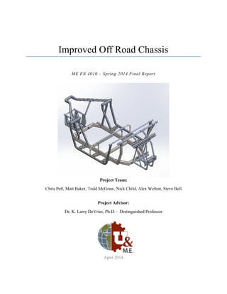
  • 1. Improved Off Road Chassis ME EN 4010 – Spring 2014 Final Report Project Team: Chris Pell, Matt Baker, Todd McGraw, Nick Child, Alex Welton, Steve Bell Project Advisor: Dr. K. Larry DeVries, Ph.D. – Distinguished Professor April 2014
  • 2. ME EN 4010 Spring 2014 April 2014 Improved Off Road Chassis Final Report i Table of Contents Table of Contents............................................................................................................................. i 1. Front Matter ............................................................................................................................. 1 1.1. Executive Summary.......................................................................................................... 1 1.1.1. Introduction................................................................................................................ 1 1.1.2. Key Focus Areas........................................................................................................ 1 1.1.3. Conclusion ................................................................................................................. 2 1.2. Acknowledgements........................................................................................................... 3 1.2.1. Student Design Team................................................................................................. 3 1.2.2. Teaching Team........................................................................................................... 4 1.2.3. Corporate Sponsors.................................................................................................... 5 1.2.4. Additional Acknowledgements.................................................................................. 5 2. Design Requirements............................................................................................................... 5 2.1. Overview........................................................................................................................... 5 2.2. Improved Repairs.............................................................................................................. 5 2.2.1. Faster and Cheaper Repairs ....................................................................................... 6 2.2.2. Easier Repairs ............................................................................................................ 6 2.3. Rigidity ............................................................................................................................. 6 2.3.1. Increase Energy Transferred to Shock Absorbers ..................................................... 6 2.3.2. Allow for Adjustments to Suspension ....................................................................... 6 2.3.3. Prevent Misalignment ................................................................................................ 6 2.3.4. Reduce Unwanted Noise............................................................................................ 7 2.4. Increased Customization................................................................................................... 7 2.4.1. Increased Rigidity...................................................................................................... 8 2.4.2. Decreased Weight ...................................................................................................... 8 2.4.3. Decreased Cost........................................................................................................... 9 2.5. Decreased Need for Welding............................................................................................ 9
  • 3. ME EN 4010 Spring 2014 April 2014 Improved Off Road Chassis Final Report ii 2.5.1. No Heat Damage........................................................................................................ 9 2.5.2. More Consistent Performance.................................................................................... 9 2.6. Widely Applicable Technology........................................................................................ 9 3. Design Specifications............................................................................................................... 9 3.1. Overview........................................................................................................................... 9 3.2. Improved Repairs............................................................................................................ 10 3.2.1. Ease of Repair.......................................................................................................... 10 3.2.2. Time of Repair ......................................................................................................... 10 3.2.3. Cost of Repair .......................................................................................................... 11 3.3. Rigidity ........................................................................................................................... 11 3.3.1. Amount of Stress...................................................................................................... 11 3.3.2. Linear Displacement ................................................................................................ 12 3.3.3. Alignment of Parts ................................................................................................... 12 3.4. Material Customization................................................................................................... 12 3.4.1. Use of Diverse Materials ......................................................................................... 12 3.4.2. Cost of Frame Manufacturing.................................................................................. 13 3.4.3. Weight of Frame ...................................................................................................... 13 3.5. Decreased Welding......................................................................................................... 13 3.6. Widely Applicable Technology...................................................................................... 13 3.6.1. Technology is Widely Accessible............................................................................ 14 3.6.2. Technology Instills a Sense of Pride in Machine..................................................... 14 4. Conceptual Design................................................................................................................. 14 4.1. Initial Concepts ............................................................................................................... 14 4.1.1. Lapped Joint............................................................................................................. 14 4.1.2. Bonded Sleeve Joint................................................................................................. 15 4.1.3. Welded Sleeve Joint................................................................................................. 15 4.2. Adhesive Selection.......................................................................................................... 15
  • 4. ME EN 4010 Spring 2014 April 2014 Improved Off Road Chassis Final Report iii 4.3. Product Architecture ....................................................................................................... 16 4.3.1. High-Level System Design...................................................................................... 16 4.3.2. Detailed Subsystems ................................................................................................ 17 5. Final Design........................................................................................................................... 17 6. Performance Verification....................................................................................................... 19 6.1.1. Physical Sleeve Joint Prototypes ............................................................................. 20 6.1.2. Analytical Modeling ................................................................................................ 22 6.1.3. Physical Testing....................................................................................................... 26 7. Project Planning..................................................................................................................... 27 7.1. Schedule.......................................................................................................................... 28 7.1.1. Fall Semester............................................................................................................ 28 7.1.2. Spring Semester ....................................................................................................... 28 8. Budget.................................................................................................................................... 31 9. Conclusion ............................................................................................................................. 32 9.1. Future Work.................................................................................................................... 32 10. References............................................................................................................................ 33 11. Appendix.............................................................................................................................. 34
  • 5. ME EN 4010 Spring 2014 April 2014 Improved Off Road Chassis Final Report 1 1. Front Matter 1.1.Executive Summary 1.1.1. Introduction The project consists of improvements on existing side by side off road vehicle frame technology. There were almost 350,000 side-by-side vehicles sold in the 2012 model year, and those numbers are expected to jump to over 375,000 vehicles during the 2015 model year. In this fast growing market, chassis technology has not seen any major improvements for some time. The Off Road Chassis design team aims to change that with the introduction of structural bonding technology to the side-by- side market. Currently, manufacturers use traditional welding processes to build frames. Welding is a tested and proven method of frame construction, but also introduces several noteworthy problems:  Welding limits frame manufacturers to the use of only one type of material; in most cases steel.  The extreme temperatures of 3100ºF and higher experienced during welding cause heat damage to frame components, and reduce the tempering of the material.  Welding makes the material more susceptible to corrosion and fatigue damage.  Repairs on a welded frame are difficult, time-consuming, and expensive. Often an entire welded frame must be replaced if any part of it is damaged.  Welding is a hazardous process, especially if attempted by a rider making repairs in their garage. The improved off road chassis will make several improvements over traditional welded designs, and will be desirable for all customers including manufacturers and end users. The improved chassis will allow the customer to utilize several different materials in each section of the frame, reduce the amount of welding used during manufacturing, and make repairs faster, cheaper, and easier, all while maintaining necessary levels of structural rigidity for customer satisfaction. 1.1.2. Key Focus Areas The goal of the project is to create a functional chassis for a Polaris RZR side-by-side off road vehicle as a proof of concept. Structural bonding using an acrylic based adhesive will be used to replace many of the welded joints in the chassis. The bonded chassis must perform at least as well as the welded chassis while making improvements in several key focus areas:  Improved repairs  Rigidity  Material customization  Decreased welding The cost of, time needed for, and complexity of repairs are some of the greatest improvements achieved with the structurally bonded chassis. Instead of replacing an entire frame, which is often the norm with welded chassis ($2000+), the structural bonding technology allows for replacement of only the damaged frame section. This technology saves the user time in the shop, and saves money in both material and labor costs.
  • 6. ME EN 4010 Spring 2014 April 2014 Improved Off Road Chassis Final Report 2 The structurally bonded chassis must perform at least as well as the original chassis in the areas of strength and rigidity to be accepted by the off road community. For this project, carbon steel similar to what is used on the original chassis was combined with 6061-T6 aluminum for construction. All FEA modeling and analysis showed that the improved chassis performs at least as well as, and often better than the original chassis in the areas of structural rigidity, static strength, and fatigue strength. The testing of the completed chassis was mostly analytical, and before the frame could safely be used on a machine, further verification through physical testing would need to be completed. The use of bonding also allows manufacturers and users the freedom to customize the materials used in the chassis. For this project one variation of steel and one variation of aluminum were used, but any number of materials could be utilized in the future including other metals or even composites. This allows for customization and optimization of weight, cost, and rigidity for each individual customer. The use of bonding technology replaced 32 welded joints in the chassis built for this project. The bonded sections of the chassis will never experience temperatures above 400°F, which reduces the amount of heat damage and corrosion cracking that would normally occur in welded sections of the frame. Hazards for workers during welding are also reduced. While this iteration of the improved chassis eliminated 32 welded joints, future iterations could increase this number to further take advantage of this technology. 1.1.3. Conclusion Structural bonding is an exciting alternative to welding in the chassis of side by side off road vehicles. The structurally bonded frame maintains the necessary geometry to be compatible with all components while making repairs cheaper, easier and faster, maintaining or increasing the rigidity of the frame, increasing the freedom to customize materials, and decreasing the need for welding. While further physical testing is needed to verify the frame is safe for normal use, the design team is confident that the bonded chassis will perform at least as well as traditional welded frames and be accepted and embraced by the off road motorsports community.
  • 7. ME EN 4010 Spring 2014 April 2014 Improved Off Road Chassis Final Report 3 1.2.Acknowledgements 1.2.1. Student Design Team Nick Child – Team Captain Nick_cem@hotmail.com Nick took on the role of team captain. He oversaw the team efforts, and coordinated meetings and tasks involved in creating the off road chassis. Nick has excellent communication, engineering, and presentation skills, as well as an extensive background in the off road motorsports industry. Steve Bell –3D Modeling and FEA skbell@eng.utah.edu Steve took on the responsibility of reverse engineering a current Polaris RZR 800 chassis and designing the new chassis in SolidWorks. He also ran all finite element analysis of the frame through ANSYS workbench. Steve brings a quality skill set and hardworking personality that served him well during his time serving in the United States Marine Corps. Matthew Baker – Manufacturing and Prototyping Mattbaker160@gmail.com Matt has always enjoyed working with his hands, and is very meticulous in his work. He brings valuable knowledge in solid mechanics as well as proficiency in SolidWorks. Matt has a background in managerial skills that will aid in guiding the team through the decision making process. Todd McGraw – Manufacturing and Material Acquisition toddjmcgraw@gmail.com Todd has 8 years of manufacturing experience, and there is not a tool in the shop that he does not have knowledge about. He has exhibited an ability to find unique parts through various resources. Todd also has great fabrication skills, especially welding, that will be valuable during the assembly process. Chris Pell – Computer Science, Solid Mechanics and Communications chrispell@hotmail.com Chris has an extensive background in computer science with notable MATLAB and C++ experience. He possesses the problem solving ability of a seasoned engineer, and has acquired a wide array of knowledge in multiple fields. Chris is also gifted with the ability to write and prepare professional quality documents.
  • 8. ME EN 4010 Spring 2014 April 2014 Improved Off Road Chassis Final Report 4 Alex Welton – Material Selection and Composites Awelton515@yahoo.com Alex has a lot of experience working with different materials and their behavioral characteristics. He will oversee the material selection for various sections of the chassis. Alex also has background in advanced strengths and composites, which was useful when discussing composite materials for subsections of the chassis. 1.2.2. Teaching Team Dr. K Larry Devries, Ph.D. – Distinguished Professor and Project Advisor kldevries@mech.utah.edu P: 801.581.7101 Dr. DeVries is an industry-leading expert when it comes to material properties, and especially the use of adhesives. He will oversee the entire project, and offer his guidance and suggestions to help the team create a high-quality finished chassis. Some of his main research interests include: failure in materials, behavior of adhesive joints, and mechanical testing of materials. Shadrach Roundy – shad.roundy@utah.edu Dr. Roundy was the lecture professor for the senior design sequence, and guided the team throughout the semester on how to manage the project and develop the product. Dr. Roundy is an expert in energy harvesting, inertial sensing, self-powered wireless sensors, and MEMS. His many years of industry experience, and his ability to convey his knowledge to the class were valuable during the design process. John Heit Heit88@gmail.com John was on the SAE Baja team in 2011-2012, and offers a wide array of knowledge that will be beneficial for the design team. His knowledge of solid mechanics, chassis modeling, and chassis manufacturing will be invaluable during the design and manufacturing process.
  • 9. ME EN 4010 Spring 2014 April 2014 Improved Off Road Chassis Final Report 5 1.2.3. Corporate Sponsors  Easton Technical Products 1.2.4. Additional Acknowledgements  Shasha Bambas - Welding Instructor at USU Eastern  Lon Youngberg - Associate Professor – Welding, USU Eastern  Chandler Peacock - Pursuing B.S. Welding Engineering, TIG Welding  Brad Child - Fabrication Assistance  Justin Child - Fabrication Assistance  Tucker Foulkes - Fabrication Assistance  Justin Jetter - Fabrication Assistance  Austin Stout - TIG Welding  Metal Supermarkets 2. Design Requirements 2.1.Overview The project requirements agreed upon by the advisor and design team for the Improved Off Road Chassis will address the needs of customers ranging from recreational “weekend warriors” to the more extreme off road enthusiasts who push their machine to the edge. For this reason, the technology must be applicable across a wide range of models. Through personal experience, and talking to experienced riders, the design team identified several important customer needs beginning with the need for quicker, cheaper, and easier repairs in the event of the frame becoming damaged. Another important customer need is the ability to customize the frame by selecting varied materials based on the requirements of each section of the chassis. This customization will allow each user optimization of cost, weight, and strength of the frame depending on the needs of individual customers. Using this technology, the user can create a more rigid, higher performance product, or a cheaper, lower performance product as needed. The design will also allow welding, and the associated heat damage, to be eliminated from several areas of the frame during the manufacturing process. Table 1 outlines the hierarchy of design requirements, and Table 2 lists the customer needs in order of importance. 2.2.Improved Repairs Currently, repairs are time consuming, difficult, and expensive for the user. If a part of a welded frame becomes damaged, either the entire frame must be replaced, or the damaged section must be cut out and a replacement part welded back in. Customers desire a chassis that is cheaper, easier, and faster to repair, so they can get back on the trail faster.
  • 10. ME EN 4010 Spring 2014 April 2014 Improved Off Road Chassis Final Report 6 2.2.1. Faster and Cheaper Repairs The design team aimed to make repairs cheaper and faster by eliminating the need to replace an entire frame. Customers want to get back on the trail as soon as possible, and waiting for an entire frame to be shipped to a dealer greatly increases the time needed for repairs. Repairs can be quite expensive due to the need to purchase a new frame, and high labor costs. It is desired that both material and labor costs be decreased for repairs. 2.2.2. Easier Repairs Along with making repairs cheaper and faster, the Improved Off Road Chassis aims to make localized repairs a reality. Instead of requiring full frame replacement, as with traditional chassis, the localized area of damage can be located, de-bonded, and replaced. This method of repairs requires no specialized welding skills, and can be accomplished by anyone with the proper tools and knowledge of the adhesive. 2.3.Rigidity The next crucial design requirement for the Improved Off Road Chassis is to increase the rigidity of the chassis. The safety and enjoyment of the vehicle all begin with a high-quality rigid chassis. A rigid chassis that is unlikely to fail will ensure that any occupants of the vehicle remain safe during use. A more rigid chassis also allows for a more enjoyable ride by allowing the shock absorbing system to create a smoother, quieter ride. 2.3.1. Increase Energy Transferred to Shock Absorbers Users want as much energy as possible from riding impacts to be absorbed by the shock absorbers. By transferring as much impact energy as possible to the shock absorbers, frame fatigue will be decreased, the dynamic response of the suspension system will be improved, and the life of the frame will increase. 2.3.2. Allow for Adjustments to Suspension Many high performance aftermarket suspension systems are highly adjustable, but require a rigid frame as the starting point for adjustments. Users tackling technical trails or difficult terrain must be able to fine-tune their suspension to the individual needs of their machine. 2.3.3. Prevent Misalignment Any flexing, bending, or twisting in the frame can cause other parts of the machine to become misaligned. Maintaining alignment will prevent failures of other systems and the associated costly repairs.
  • 11. ME EN 4010 Spring 2014 April 2014 Improved Off Road Chassis Final Report 7 2.3.4. Reduce Unwanted Noise Designing a more rigid frame will decrease noise due to movement of plastic parts, and doors rattling. A structurally bonded frame using ideal materials will reduce unwanted noise during high performance. Table 1. Hierarchy of Design Requirements Primary Need Secondary Need  More rigid frame  More impact energy transferred to shock absorbers instead of frame  Precisely adjustable suspension  Prevent parts from becoming misaligned  Less unwanted noise during use  Increased customization ability for manufacturer and/or end user (Ability to choose different materials for different areas of the frame)  Increased rigidity in high stress areas  Decreased weight in low stress areas  Lower costs by way of material selection  Improved repairs  Quicker and cheaper repairs  Easier to repair in specific locations  Decrease need for welding during manufacturing  No heat damage during manufacturing  More consistent performance from machine to machine  Technology applicable across wide range of models 2.4.Increased Customization When using welding techniques to manufacture a frame, similar materials must be used throughout the entire frame. It is desired by manufacturers and end users alike that unique materials can be selected for different sections of the chassis. This not only allows the
  • 12. ME EN 4010 Spring 2014 April 2014 Improved Off Road Chassis Final Report 8 manufacturer and user more options when building their desired machine, but also allows for gains in the areas of rigidity, weight, and cost. Table 2. Customer Needs Ranked From Most Critical (5) to Least Important (1) Number Need Importance 1 Easier to repair in case of damage 5 2 Ability to choose different materials for different areas of the frame 5 3 Quicker repairs 4 4 More rigid frame 4 5 More impact energy transferred to shock absorbers instead of frame 3 6 Prevent parts from becoming misaligned 3 7 Technology applicable across wide range of models 3 8 Decreased cost for manufacturer and/or end user 3 9 Decreased weight in frame 3 10 Cheaper repairs 3 11 Precisely adjustable suspension 3 12 More consistent performance from machine to machine 3 13 Less heat damage to metal parts during welding process due to decreased welding 3 14 Less unwanted noise during use 1 2.4.1. Increased Rigidity From Table 2 and section 2.3 it can be seen that a more rigid frame is an important design requirement. Structural bonding will allow for more expensive, stronger materials to be used only as needed in high stress areas of the. 2.4.2. Decreased Weight To increase machine performance it is desirable to decrease the weight of the chassis. Structural bonding allows lighter materials to be used in the frame without the need for special fasteners and connections.
  • 13. ME EN 4010 Spring 2014 April 2014 Improved Off Road Chassis Final Report 9 2.4.3. Decreased Cost Users desire a high quality product at the best price possible. Through the use of different materials the manufacturer and end user can closely control the cost and quality of the chassis. A user who does not require a top of the line machine can choose to use less expensive materials to decrease overall cost. 2.5.Decreased Need for Welding Welding during manufacturing and repairs requires special tools and training, is hazardous for the laborer, and can cause heat damage and decreased strength in the critical areas of the frame due to the high temperatures used during welding. The use of structural bonding technology greatly diminishes the need for welding in the off road chassis. 2.5.1. No Heat Damage Localized pockets of heat damage or softening are encountered in a traditional chassis due to the welding process. Structural bonding requires no heat during assembly and only temperatures of 400° F if a part must be removed. The low temperatures used eliminate defects due to heat. 2.5.2. More Consistent Performance The defects and variations in weld quality lead to variation in the feel and performance of each individual chassis. Structural bonding will reduce this variability from frame to frame leading to more consistent performance for each user. 2.6.Widely Applicable Technology Once the base technology is developed, it can be adapted to fit a wide range of models. Structural bonding can be used for basic low-end machines, or for high-end performance machines. Structural bonding allows slight changes to be made in the quality and size of materials to transform a low-end chassis into a frame fit for a top of the line model. 3. Design Specifications 3.1.Overview The design specifications for the Improved Off Road Chassis design project focus on improving the repair process, increasing rigidity of the frame, increasing customization options for the frame, decreasing the need for welding, and developing a technology that is applicable across a wide range of models. By considering the metrics, and meeting or exceeding the design specifications outlined in Tables 3 - 7, the Off Road Chassis design team aims to produce a successful product that is desirable to the customer. The structurally bonded chassis design will provide the customer with a higher quality machine than is currently available.
  • 14. ME EN 4010 Spring 2014 April 2014 Improved Off Road Chassis Final Report 10 Several members of the design team have extensive experience using and selling off road vehicles. Personal experience, feedback from customers, and talking to other experienced users were all tools utilized during the process of determining design specifications. It was determined that many design specifications must either meet (marginal value) or exceed (ideal value) the performance of the original equipment manufacturer (OEM) frame. In these cases finite element analysis (FEA) was used extensively to benchmark the current design, and set target specifications for the improved chassis. FEA results will be discussed further in section 6. 3.2.Improved Repairs A unique feature of the structurally bonded frame is the ability to perform quicker, cheaper, and easier repairs. The improved repairs will be a significant step up from conventional welded designs, and will be a very desirable characteristic in side-by-side vehicles. Table 3 displays all design specifications directly related to repairs. Table 3. – Design Specifications Related to Repairs Metric # Customer Need # Metric Importance (1-5) Units Marginal Value/ Range Ideal Value 3.2.1 1, 2, 3, 10 Ease of repair (1 – easiest, 5 – hardest) 5 Subj. (1-5) 3 2 3.2.2 1, 3 Time needed to repair frame 4 Hr. < 5 < 2 3.2.3 1, 2, 3, 10, 13 Cost of repairs to frame 3 $ < 1000 < 750 3.2.1. Ease of Repair Typically when a frame is damaged, a piece must be cut out and a replacement welded in, or the entire frame must be replaced. Unless the user has specialized welding experience, a damaged frame must be taken to a dealer or repair shop for repairs. The structural bonding method will be easy enough to perform that the user can perform most repairs at home in the comfort of their own garage without the need for specialized equipment. On a subjective scale from 1 (easiest) to 5 (hardest) repairs on the structurally bonded chassis should be in the 2 – 3 range as compared to 5 for the welded chassis. 3.2.2. Time of Repair Structural bonding will allow for repairs of single parts, avoiding the need to disassemble the entire vehicle. By eliminating much of the disassembly and reassembly process, the structural bonding method will save a significant amount of time. While time must be allowed for the bonding agents to reach their full operating strength (~24 hours), the adhesive will reach handling strength within roughly one hour. Actual labor time to make repairs will
  • 15. ME EN 4010 Spring 2014 April 2014 Improved Off Road Chassis Final Report 11 be low compared to welded repairs. Repairs using structural bonding technology should take 2 – 5 hours when compared to the days that repairs on a welded frame often require. 3.2.3. Cost of Repair Using structural bonding will allow a damaged chassis to be repaired by buying only one or two parts instead of purchasing an entirely new frame. Labor costs for structural bonding repairs will be lower than the labor costs for typical welding repair methods because the repairs can be completed at home. Repair costs on a structurally bonded frame should be between $200 and $300 as compared to $2000+ to replace a damaged welded frame. 3.3.Rigidity The design of any vehicle starts with the chassis, and one of the most important characteristics of the chassis in an off road vehicle is structural rigidity. The chassis must be able to absorb impacts while keeping the rider safe, and maintaining a solid support structure for other components of the vehicle. Table 4 displays all design specifications directly related to rigidity. Table 4. – Design Specifications Related to Rigidity Metric # Customer Need # Metric Importance (1-5) Units Marginal Value/ Range Ideal Value 3.3.1 2, 4, 5, 6, 11 Maximum stress experienced during simulated random vibration analysis 4 ksi < 29 < 25 Maximum stress experienced during simulated static load on front suspension ksi <60 < 40 3.3.2 2, 4, 5, 6, 14 Simulated linear displacement of frame under static loading on front suspension 4 in < 2.45 < 2 3.3.4 4, 6, 14 All parts remain in proper alignment (3.3.1 and 3.3.2 satisfied) 3 binary yes yes 3.3.1. Amount of Stress The most important function of any off road vehicle chassis is keeping the occupants of the vehicle safe. Failure of any part of the frame can lead to an accident resulting in bodily injury to the occupants. Fatigue stress levels in the improved frame during random vibration simulations should remain at or below the 29 ksi stress levels seen by the OEM chassis.
  • 16. ME EN 4010 Spring 2014 April 2014 Improved Off Road Chassis Final Report 12 3.3.2. Linear Displacement The amount of linear displacement in the frame will be determined using analytical tests. Less deformation in the frame leads to better suspension performance, more precise adjustability of the suspension, and less chance that other parts of the machine will become misaligned during use. The improved chassis must perform at least as well as the 2.45 in displacement seen in the OEM chassis during simulated static loading. 3.3.3. Alignment of Parts Misalignment of any parts during use can lead to critical malfunctions. Movement in plastic parts of the machine can also contribute to unwanted noise during operation, detracting from the overall user experience. The parts of the improved chassis should move less than parts in the original chassis. If specifications 3.3.1 and 3.3.2 are met, it will be assumed that parts will remain within an acceptable level of displacement, and specification 3.3.3 will also be met. 3.4.Material Customization One of the most unique and important aspects of the Improved Off Road Chassis design is the ability to select unique materials for different sections of the frame. Using structural bonding allows material choice to be based on necessary functionality for each individual section. The ability to customize materials allows for more choices in the cost, quality and weight of the frame. Stronger materials may be selected for areas of the frame where rigidity is crucial; this will improve performance of the design specifications discussed in section 3.3. Table 5 displays all design specifications directly related to material customization. Table 5. – Design Specifications Related to Material Customization Metric # Customer Need # Metric Importance (1-5) Units Marginal Value/ Range Ideal Value 3.4.1 2, 4, 7, 8, 9, 10 Different materials may be used for different parts of the frame (number of materials used) 5 # 2 3 3.4.2 2, 8 Cost of frame manufacturing 3 $ < 900 <800 3.4.3 2, 9 Weight of frame 3 lbs <120 <90 3.4.1. Use of Diverse Materials Unlike welding where only similar materials may be used, structural bonding will allow for joining of unlike materials throughout the frame. This will create more customization
  • 17. ME EN 4010 Spring 2014 April 2014 Improved Off Road Chassis Final Report 13 options for the manufacturer and the end user. More customization options will lead to more options in material cost and weight, while ensuring that strength needs are met in critical areas of the frame. At least two different materials will be used in the construction of the improved chassis. 3.4.2. Cost of Frame Manufacturing Due to decreased welding and the ability to select diverse materials, the overall manufacturing costs of a structurally bonded chassis can be accurately controlled. A middle of the line (steel and aluminum) improved chassis must be manufactured for less than approximately $900.00 to be competitive with current welded designs. 3.4.3. Weight of Frame The overall weight of the frame is an important factor in performance. Structural bonding techniques will allow for improved weight characteristics in the chassis. Overall weight will be determined by the manufacturer or end user. The chassis being constructed for this project must be lighter than the OEM chassis (120 lbs.) and will ideally weigh less than 90 lbs. 3.5.Decreased Welding Decreasing the amount of welding in the design is desirable for both the manufacturer and the end user. Welding is time consuming, and causes localized heat damage due to the extreme temperatures. Structural bonding eliminates the need for temperatures higher than 400°F, avoiding any heat damage to frame materials. Decreasing the amount of welding also is beneficial in the areas of customization, cost, and ease of repairs. Table 6 displays the design specification directly related to welding. Table 6. – Design Specification Related to Welding Metric # Customer Need # Metric Importance (1-5) Units Marginal Value/ Range Ideal Value 3.5 1, 2, 3, 8, 10, 12, 13 Number of welded joints eliminated 3 # >20 >30 3.6.Widely Applicable Technology Ultimately structural bonding technology should be applicable across a wide range of models. The increased customization and decreased welding will allow the technology to be applied from the most basic model to high-end performance machines. Table 7 displays all design specifications directly related to technology.
  • 18. ME EN 4010 Spring 2014 April 2014 Improved Off Road Chassis Final Report 14 Table 7. – Design Specifications Related to Technology Metric # Customer Need # Metric Importance (1-5) Units Marginal Value/ Range Ideal Value 3.6.1 2, 7, 8 Frame technology is applicable across a wide range of models 3 binary yes yes 3.6.2 1, 2, 5, 14 Frame instills a sense of pride in the machine (1 – lowest, 5 – highest) 2 Subj. (1-5) 4 5 3.6.1. Technology is Widely Accessible Structural bonding technology should benefit all types of off road users from the low-end recreational users to high-end performance users. The ability to customize materials will allow a basic, inexpensive model to be created using less expensive materials. The technology can also be used with higher quality materials to create a more expensive, higher- end model. 3.6.2. Technology Instills a Sense of Pride in Machine Manufacturers and customers selling and buying this technology will feel a sense of pride when showing or riding in a structurally bonded chassis. Structural bonding will be an exciting innovation in the off road industry, and off road enthusiasts will be eager to use it in their machines. 4. Conceptual Design To maintain compatibility with all existing parts, the geometry of the improved chassis had to match that of the OEM chassis. An OEM chassis was acquired and reverse engineered to determine the geometry of the improved frame. Certain joints were selected for replacement of welding with bonding, modifications were made to the frame to ensure all customer needs were addressed, and all design specifications met. 4.1.Initial Concepts Brief descriptions of the different initial joint design concepts are listed below. To successfully reverse engineer the OEM chassis and improve upon it, joint design will be critical for a successful chassis. 4.1.1. Lapped Joint This joint takes two members and connects them by over lapping them (often on a flat face) and bonding the overlapped section.
  • 19. ME EN 4010 Spring 2014 April 2014 Improved Off Road Chassis Final Report 15 4.1.2. Bonded Sleeve Joint This Joint takes a larger diameter tube as the female and a smaller diameter as the male. This joint is similar to a standard lapped joint, but gives the joint a larger bond area than the lapped joint. This joint design was used most extensively in the final design due to the large bond surface area. 4.1.3. Welded Sleeve Joint Similar to the bonded sleeve joint, this joint welds multiple larger diameter tubes allowing members to be joined at any angle. 4.2.Adhesive Selection The most important part of the joint design in the improved chassis is the adhesive. There were multiple criteria to consider while ensuring the proper adhesive was chosen to meet the customer needs. The two main criteria of concern were the ability to remove and replace a damaged member from a joint, and the ability of the adhesive to withstand at least 2750 psi in tension. Table 8 aided in the selection of the final adhesive used in the chassis. Table 8. Selection Matrix for Structural Bonding Adhesive Selection Criteria Lord 406/19 Acrylic Loctite Acrylic Gorilla Epoxy Devcon Generic Epoxy 3M Epoxy Ability to reheat and break the bond + - - - + Environmentally resistant + + + + + No-Sag + - + - + Versatile material selection + + + 0 + Tensile Strength + + 0 - - Operating Temp 0 0 0 0 + Handling Time 0 + 0 + 0 Net Score 5 3 3 3 5 Rank 1 3 4 5 1 Continue? Yes Yes No No Yes
  • 20. ME EN 4010 Spring 2014 April 2014 Improved Off Road Chassis Final Report 16 The Lord 406, Loctite acrylic, and 3M adhesives were selected for further analysis. Physical prototypes were built to test the properties of each adhesive in a tensile load frame. These tests are discussed further in section 6. Ultimately because of the mix of good mechanical properties, and ability to release the bond, the Lord 406 adhesive was selected for final construction. 4.3.Product Architecture 4.3.1. High-Level System Design A high-level system diagram was created and can be seen in Figure 1. The diagram illustrates the five main subsystems identified in the Improved Off Road Chassis. The main “chunks” are the front suspension, main chassis, rear suspension, steering/dash, and the aesthetic side portions. These high level “chunks” are also presented in a rough geometric layout in Figure 2. Figure 1 – High-level system diagram of the chassis showing the five main subsystems. Figure 2 – Geometric layout of system with geometric location of the main chunks shown. Chassis Front Suspension Main Supports Rear Suspension Steering/Dash Aesthetic pieces / Body Supports
  • 21. ME EN 4010 Spring 2014 April 2014 Improved Off Road Chassis Final Report 17 4.3.2. Detailed Subsystems After identification of the five main subsystems, each of those subsystems was broken down into more detailed subsystems. One of the great advantages of the structurally bonded frame is the ability to customize material choice in each area or subsystem of the frame. In the improved chassis, the main chassis section was made entirely of steel as it will undergo the highest loads. The front suspension and rear suspension subsystems were created using a mix of steel and 6061-T6 aluminum to maintain structural rigidity and integrity while decreasing the overall weight of frame. The steering/dash and aesthetic subsystems were created entirely out of aluminum because they do not support any large loads. 5. Final Design The final design of the structurally bonded off road chassis integrated the geometry of the OEM chassis with the bonded joints required to meet customer needs and design specifications. For this, the design team used three metals and the Lord 406/19 acrylic adhesive. The front and rear suspension subsections were fabricated from 6061-T6 aluminum, while the main base structure was built from mild carbon steel with 4130 chromoly tubing used as mounting sleeves for the front and rear subsystems. These subsections were then bonded using Lord 406/19 acrylic adhesive. The choice of adhesive was critical to design requirements and specifications. Testing determined that several adhesives were near the specified 2750 psi shear strength. However, the only adhesive that allowed for easy de-bonding was the Lord 406 acrylic adhesive. Because this adhesive met strength specifications while also allowing for improved repairs, it was selected for final construction. The prototype chassis was designed to display the advantages of the structural bonding method while keeping the dimensions of the OEM chassis for proof of concept purposes. This prototype has shown the following:  The structural bonding method has the potential for widespread use in off road chassis manufacturing  Lighter weight in conjunction with increased strength is possible through structural bonding  Ease of repairs for the average consumer is improved over the OEM chassis, and can be reasonably performed from home The final SolidWorks model of the improved chassis is presented in Figure 3. The darker grey areas were fabricated from mild carbon steel and the lighter grey areas were made with 6061-T6 aluminum. The bill of materials used in construction of the frame is presented in Table 9. More
  • 22. ME EN 4010 Spring 2014 April 2014 Improved Off Road Chassis Final Report 18 information from SolidWorks models can be found in the appendix, and complete SolidWorks models can be provided electronically as necessary. Figure 3 – 3D model of improved chassis showing steel sections (lighter brown/gray) and aluminum sections (darker gray). The frame constructed for this project used only two types of materials to prove that structural bonding is a viable concept, and can maintain the necessary strength characteristics to compete with the OEM chassis. In the future, additional materials, including additional metals and composites could be utilized in the frame as desired. SolidWorks models of each major subsection, and an exploded view showing all bonded joints can be found in the appendix. Aluminum Steel
  • 23. ME EN 4010 Spring 2014 April 2014 Improved Off Road Chassis Final Report 19 Table 9. Bill of Materials for Improved Off Road Chassis CHASSIS BILL OF MATERIALS Steel Dimensions Thickness Description QTY Vendor Price 1.25" x 1.25" 1/16" Square Tubing 5 ft Metal Supermarkets $8.50 1" x 1" 1/16" Square Tubing 14 ft Metal Supermarkets $15.00 6" x 10" 1/16" Sheet 6 Pieces Metal Supermarkets $7.00 30"x30" 1/16" Sheet 1 Piece Metal Supermarkets $36.00 Aluminum Dimensions Thickness Description QTY Vendor Price 1.25" x 1.25" 1/16" Square Tubing 10 ft Metal Supermarkets $30.00 1.5" x 1.5"` 1/16" Square Tubing 7 ft Metal Supermarkets $24.00 1" x 1" 1/16" Square Tubing 12 ft Metal Supermarkets $15.00 1.75" OD 1/16" Round tube 3 ft Metal Supermarkets $13.25 1.5 OD" 1/16" Round tube 5 ft Metal Supermarkets $10.50 1.25" OD 1/16" Round tube 20 ft Metal Supermarkets $40.00 1" OD 1/16" Round tube 22 ft Metal Supermarkets $30.00 10" x 24" 1/16" Sheet 1 Piece Metal Supermarkets $7.75 16" x 10" 1/16" Sheet 1 Piece Metal Supermarkets $4.00 14" x 10" 1/8" Sheet 6 Piece Metal Supermarkets $45.00 Adhesives Product Description QTY Vendor Price Lord 406/19 Acrylic Based Adhesive 5Tubes Lord Adhesives $105.00 Total Cost $391.00 6. Performance Verification Both physical and analytical tools played a large part in the testing and performance verification of the improved chassis. Testing methods and results are discussed in the following sections, and values achieved for each design specification are displayed in Table 10. Some values were determined during physical and analytical testing, while others were determined based on experiences constructing the chassis.
  • 24. ME EN 4010 Spring 2014 April 2014 Improved Off Road Chassis Final Report 20 6.1.1. Physical Sleeve Joint Prototypes Figure 4 – Photographs of bonded and welded physical prototype joints. A close up view on the right shows the joints after they were loaded to failure. Figure 5 – Photograph of a bonded joint, setup for testing on a load frame in the Strengths of Materials lab. To aid in the selection of the best adhesive, four different adhesives were tested on prototype overlapping tube joints. The prototype joints were loaded in tension until failure, or until the operator became uncomfortable continuing the test. For visualization of the joint geometry and testing setup please see Figures 4 and 5, respectively. The results of this first round of prototype testing are shown in Figure 6. From the results it was determined that all adhesives performed comparably to each other. No one adhesive seemed to have a distinct advantage, while the Devcon epoxy was the only adhesive that appeared to perform worse than the others. While some adhesives failed before others, in most cases this was attributed to variation in surface prep and poor application during construction of some joints. Because it performed comparably to all other adhesives, and had Welded joint Bonded joints Bonded joint Welded joint Bonded Joint
  • 25. ME EN 4010 Spring 2014 April 2014 Improved Off Road Chassis Final Report 21 the added benefit of being de-bondable, the Lord 406 acrylic adhesive was selected to move forward with further testing, and ultimately final construction. Figure 6 – Approximation of shear stress in each adhesive during testing of four different adhesives. The maximum shear stress at failure or unloading is noted in the figure for each adhesive. Please note that the strain hardening apparent in joint constructed with 3M adhesive was due to strain hardening of the base material, and was not attributed to the adhesive. Another round of prototype joints was created to analyze how the overlap length of each joint affected mechanical properties, and compare results to a welded joint. Four bonded joints and one welded joint were created using aluminum tubing and Lord 406/19 adhesive. Overlaps in the bonded joints ranged from one inch to three inches. Figure 7 – Stress/strain response for four bonded, and one welded aluminum joints with stress at failure or unloading noted on the plot. Yield stress of 7075-T0 aluminum is approximately 15 ksi.
  • 26. ME EN 4010 Spring 2014 April 2014 Improved Off Road Chassis Final Report 22 The team was pleased to find that the bonded joints behaved very favorably compared to the welded joint. Stress/strain behavior was very similar in the bonded and welded joints (see Figure 7), validating the fact that a bonded joint will act similarly to a welded joint. The adhesive failed in some joints, but in all cases the joint base material began to yield before failure. Many of the bonded joints failed adhesively, indicating that surface prep and application methods still needed improvement. The welded joint did not fail completely, but after inspection it was found that the weld might have been faulty. Because of this, another round of prototypes were necessary. For the final round of physical prototypes two bonded steel joints were created using Lord 406 adhesive, and a similar welded steel joint was also created. As seen in Figure 8, the stress/strain response of the bonded joints was very similar to the welded joint, verifying that the Lord 406 adhesive can be used in the chassis as a suitable substitute for a welded joint. In all cases the base metal began yielding before failure at the joint. The welded joint never completely failed, while the bonded joints failed cohesively very near the stresses specified by the manufacturer, indicating that surface prep and application methods had been improved. The bonded joints did not reach the same ultimate strength before failure as the welded joint, but this may be desirable in the bonded chassis so that failure occurs in the adhesive which can be replaced, rather than in a structural member which cannot be easily replaced. Figure 8 – Stress/strain response for two bonded, and one welded steel joints. As seen in the plot, base material began to yield before failure was reached. 6.1.2. Analytical Modeling Finite Element Analysis was conducted on the 3D model of the chassis with ANSYS Workbench version 14.5. There were two major analyses that were conducted: a modal and random vibration, and a static loading. Initial analysis on the OEM chassis provided a
  • 27. ME EN 4010 Spring 2014 April 2014 Improved Off Road Chassis Final Report 23 benchmark for the design of the improved chassis. Many design specifications for the improved chassis were set to meet or beat the results of the OEM chassis. Models were imported from SolidWorks Education Edition 2013 into ANSYS Workbench in order to keep them in their native file format, as this reduces potential sources of error in the analysis. The meshing of the parts was refined iteratively until a convergence criteria of 1% was achieved; that is, until the Von Mises Stress in the model changed by no more than 1%. The vibrational load inputs came from data provided in MIL-STD-810G, and were applied at the suspension mounting locations. This loading scenario represents vehicle usage with an average speed of 26 km/hr in an environment that was 65% off-road, with 1/3 of the off-road usage considered “severe”. The failure mode of the loading was fatigue, which is represented by stress in the material. Figure 9 – Random vibration input for modal analysis of OEM chassis. The results from the modal analysis showed the first several natural frequencies to be higher in the improved chassis than for the OEM chassis, which is desired because higher frequencies are less likely to be experienced during vehicle usage. Results from the random vibration analysis showed that the fatigue stress in the improved chassis was lower than the fatigue stress in the OEM chassis. Fatigue stresses were 29,100 psi for the OEM chassis and 28,900 psi for the improved chassis.
  • 28. ME EN 4010 Spring 2014 April 2014 Improved Off Road Chassis Final Report 24 Figure 10 - Frequency normal modes for the OEM and improved chassis from the modal analysis. Figure 11 - Fatigue stress results in the OEM chassis from the random vibration analysis. 0.000 20.000 40.000 60.000 80.000 100.000 120.000 140.000 160.000 0 5 10 15 20 25 Frequency(Hz) Mode Modal Analysis Results (OEM vs Improved Chassis) OEM Improved
  • 29. ME EN 4010 Spring 2014 April 2014 Improved Off Road Chassis Final Report 25 Figure 12 - Fatigue stress results in the improved chassis from the random vibration analysis. The same convergence criteria of 1% change in Von Mises stress was used for a static deflection analysis. This analysis was used as a baseline to analyze the stiffness of each chassis as well as to provide a benchmark for verification of the Finite Element Analysis. Each chassis was fixed from the bottom of the rear, main member and a 500 pound load was applied to the forward most suspension mounting location. Again, the bonded chassis improved on the performance of the OEM chassis by displaying a maximum total deflection of 1.57 inches compared to 2.45 inches for the OEM chassis. Figure 13 - Total deformation of the improved chassis from the static structural analysis. The rear end was constrained and the load applied at the front of the chassis.
  • 30. ME EN 4010 Spring 2014 April 2014 Improved Off Road Chassis Final Report 26 Figure 14 - Total deformation of the OEM chassis from the static structural analysis. 6.1.3. Physical Testing Physical testing is important for any product, and this one is no exception. However, large- scale physical testing of the improved chassis has not been performed in the time allotted for this project. The improved chassis was bolted to the deck of a semi sized flatbed trailer. A car jack was then used to load the front suspension mounting point of the frame. With the equipment available, accurate deflection measurements were not feasible. Due to limits on the load capability, and small amounts of deflection, the team was not able to gather measurements that were accurate and consistent enough to report. The improved chassis was also lacking many mounting brackets and other pieces that came on the OEM chassis. None of these parts were used in the 3D modeling and FEA for either chassis. These extra pieces, while not load bearing, introduced additional support and rigidity to some parts of the OEM chassis. Because of this, any testing performed on the improved chassis could not be directly compared to the physical benchmarking performed on the OEM chassis. Before the chassis could safely be used in a physical machine, extensive physical testing would need to be completed. With more time and resources, physical testing would be completed by the design team to further verify claims made about the improved chassis.
  • 31. ME EN 4010 Spring 2014 April 2014 Improved Off Road Chassis Final Report 27 Table 10. – Results Achieved by Structurally Bonded Off Road Chassis Metric # Customer Need # Metric Imp. (1-5) Units Marginal Value/ Range Ideal Value Improved Chassis Value 3.2.1 1, 2, 3, 10 Ease of repair (1 – easiest, 5 – hardest) 5 Subj. (1-5) 3 2 2 3.2.2 1, 3 Time needed to repair frame 4 hr < 5 < 2 3 3.2.3 1, 2, 3, 10, 13 Cost of repairs to frame 3 $ < 1000 < 750 650 3.3.1 2, 4, 5, 6, 11 Maximum stress experienced during simulated random vibration analysis 4 ksi < 29 < 25 28 Maximum stress experienced during simulated static load on front suspension ksi <60 < 40 51 3.3.2 2, 4, 5, 6, 14 Simulated linear displacement of frame under static loading on front suspension 4 in < 2.45 < 2.00 1.57 3.4.1 2, 4, 7, 8, 9, 10 Different materials may be used for different parts of the frame (number of materials used) 5 # 2 or more 3 or more 2 3.4.2 2, 8 Cost of frame manufacturing 3 $ < 900 <800 $840.00 3.4.3 2, 9 Weight of frame 3 lbs <120 <90 74 3.5 1, 2, 3, 8, 10, 12, 13 Number of welded joints eliminated 3 # >20 >30 32 3.6.1 2, 7, 8 Frame technology is applicable across a wide range of models 3 binary yes yes yes 3.6.2 1, 2, 5, 14 Frame instills a sense of pride in the machine (1 – lowest, 5 – highest) 2 Subj. (1-5) 4 5 4 7. Project Planning To help the team plan upcoming deadlines and stay on track to meet the deadlines, a design structure matrix (DSM), milestones table, Gantt chart were utilized. During the planning phase the team laid out an anticipated schedule, and used the DSM and Gantt chart to aid in visualization of the schedule, critical path, and design deadlines. The DSM and Gantt chart were very detailed during fall semester, but were vague for the spring semester. Once the needs for
  • 32. ME EN 4010 Spring 2014 April 2014 Improved Off Road Chassis Final Report 28 spring semester were more thoroughly understood, the milestones table was created to highlight the most critical deadlines, and the desired completion date for each milestone. As the project progressed, these tools allowed the team to understand if the project was ahead of schedule, on time, or behind schedule. The schedule and schedule tools were updated throughout the project as some tasks were completed ahead of time while others took more time and effort than expected. The DSM used by the team can be found in Figure 15, the milestones table in Table 11, and the Gantt chart is displayed in Figure 20 of the appendix. 7.1.Schedule 7.1.1. Fall Semester During the fall semester some unforeseen difficulties were experienced that delayed some aspects of the project. Constructing a working model to use with ANSYS took longer than expected, and was completed after the anticipated completion date. In a similar manner the team experienced some delays during material acquisition before building of the physical prototypes. The Gantt chart allowed the team to quickly see what other aspects of the project could potentially be delayed by these setbacks, and adjust future deadlines and workloads accordingly. By using the Gantt chart, DSM, and good teamwork, all significant deadlines such as the CFP presentations were still met on time. 7.1.2. Spring Semester As seen in Table 11, all milestones early in the spring semester were completed on or ahead of schedule. It was anticipated that the most challenging and time consuming parts of the project would be final construction and testing at the end of the semester, which proved to be true. For this reason strides were made early in the semester to complete milestones early to allow more time at the end of the semester for final fabrication and testing.
  • 33. ME EN 4010 Spring 2014 April 2014 Improved Off Road Chassis Final Report 29 Figure 15 - The Design Structure Matrix used for the off road Chassis senior design project. Each “X” represents tasks that are dependent on each other.
  • 34. ME EN 4010 Spring 2014 April 2014 Improved Off Road Chassis Final Report 30 Table 11. – Spring Semester Milestones Table Milestone Date Rev. Date Completed Status Complete Modal and Random Vibration Analysis 1/9/2014 1/7/2014 Complete Build Second Round of Prototype Joints 1/17/2014 1/15/2014 Complete Design Review #1 1/24/2014 Test Second Round of Prototype Joints 1/24/2014 1/21/2014 Complete Build 3D Model of Structurally Bonded Frame 2/12/2014 2/12/2014 Complete Complete FEA on Bonded Frame Using Static Loading and Vibrations 2/19/2014 2/19/2014 Complete Design Review #2 2/21/2014 Complete Final Material Selection and Purchasing 2/24/2014 2/24/2014 Complete Build Main Structural Support Sections of Frame 3/19/2014 2/8/2014 2/8/2014 Complete Design Review #3 3/21/2014 Build Front and Rear Subsections of the Frame 3/28/2014 3/28/2014 Complete Complete Final Bonding and Construction of Frame 3/30/2014 3/31/2014 Complete Complete Testing on Structurally Bonded Frame 4/7/2014 Replaced with further analytical testing Design Day 2014 4/15/2014
  • 35. ME EN 4010 Spring 2014 April 2014 Improved Off Road Chassis Final Report 31 8. Budget The budget for the development of the Improved Off-Road Chassis prototype came from a private donor who chose to remain anonymous, and from the student course fees paid by the six members of the design team. These two funding sources combined provided $5600.00 for the team to work with while working on the project. The major costs for the prototype development process included the cost to obtain an OEM chassis for reverse engineering, and the cost of the raw materials and tools associated with building the prototype. The aluminum tubing used for testing was donated to the team by Easton Technical Products, which saved a substantial amount of money early in the project. Table 12 below shows the budget for the project, various expenditures, and the remaining funds after the prototype was complete. Table 12. - Budget for Improved Off Road Chassis Prototype. Item Quantity Cost ($) Private funding (chose to remain anonymous) -- $5,000.00 Funding from student course fees 6 Students/ $50.00/ Student/ Semester $600.00 7075-T0 aluminum tubing (For Initial Testing) 100 feet donated 6061-T4 aluminum (For Initial Testing) 24 feet donated Carbon Fiber Tubing (Not used) 2 feet donated Complete Polaris RZR chassis for reverse engineering 1 $1,200.00 Lord 406/19 adhesive 50 ml (5 tubes) $105.00 Loctite Epoxy Quick Set 1 tube $4.90 Devcon adhesive 1 tube $3.88 3M Scotch-weld 460 1 tube $17.00 Miscellaneous tools Various $30.00 Welding Materials (Wire, Shielding Gases, Tips) Various $145.00 Chassis raw materials (Steel and Aluminum) Various $573.00 Machine Time (Waterjet use) 30 minutes $18.50 Design Day Materials Various $13.50 Initial Budget $5,600.00 Total Expenditures $2,110.78 Remaining Budget $3,489.22 Table 12 above shows the approximate costs to develop the prototype off-road chassis. The approximate cost of development was $2100, with approximately $840.00 going into the construction of the final prototype chassis. Of this cost, raw materials were the biggest expense. This is due to the high amount of waste incurred while fabricating the chassis. The bill of materials in Table 9 shows that the actual cost for the material on the chassis was less than $400.00, while the amount spent on raw materials was approximately $680.00. This equates to approximately 40% waste, which would be greatly reduced once the manufacturing process was
  • 36. ME EN 4010 Spring 2014 April 2014 Improved Off Road Chassis Final Report 32 refined. When considering what it would cost to build a single chassis, labor must be taken into account. The design team spent between 350 and 400 man hours fabricating and building this prototype chassis. However, of these hours, there was usually one or two unnecessary people working, and because of the nature of building a prototype, the fabrication of the chassis was a very inefficient endeavor. Therefore, it is estimated that a chassis built in a production environment by skilled workers with all of the necessary equipment, tooling, and jigs to build the chassis would take less than twenty hours. At a typical labor rate of $15.00/ hr. for a skilled assembly worker, this translates to a labor cost of approximately $300.00 per unit for the manufacturer. The raw material cost paid by the design team was also much higher than a large-scale manufacturer would pay for the same materials. This can be attributed to the massive quantities of raw materials that the manufacturer would be ordering, and their ability to buy raw materials at times when prices are lowest to keep raw materials in inventory until they are needed. Therefore, it is estimated that the manufacturer would pay approximately 30-40% less for raw materials than the average retail customer. This translates to a raw material cost of approximately $240.00- $280.00 per unit for the manufacturer. Combining the estimated labor and raw material cost for the manufacturer, it is estimated that the cost to manufacture one unit would be approximately $500.00 - $600.00. These estimates do not include any overhead cost for the manufacturer and would be slightly higher in reality. 9. Conclusion Overall the design and construction of the improved bonded off road chassis was successful. The prototype was a successful proof of concept showing that structural bonding can be a viable replacement for welding in the construction of off road vehicle chassis. The prototype met customer needs and design specifications through implementation of structural bonding. The improved chassis prototype successfully showed improvements over the OEM chassis by making the repair process easier and more manageable for an average user. The prototype also successfully implemented two materials into the frame, showing that the user can customize the weight, cost, and strength of the frame. The geometry of the OEM frame was kept, and the testing performed indicates that the strength and rigidity characteristics of the improved chassis will meet or exceed the original frame. 9.1.Future Work Future tasks consist mostly of much more physical testing of the prototype frame. Much more strenuous physical testing must be performed on the improved chassis before it can be deemed
  • 37. ME EN 4010 Spring 2014 April 2014 Improved Off Road Chassis Final Report 33 safe for use in a full-scale machine. The additional physical testing should focus on deflection of the frame under static loading, fatigue testing, and testing under simulated weather conditions for corrosion, and can be compared to benchmarks acquired by identical testing on the OEM chassis. Future work will also include experimentation with additional materials in the frame. The use of additional metals and composite materials will be tested both analytically and physically to verify that customers truly will have nearly unlimited options when building a chassis for their machine. 10.References  Davis, Max, and John Tomblin. Best Practice In Adhesive-Bonded Structures and Repairs. National Institute for Aviation Research for U.S. Department of Transportation, Apr. 2007.  Nemes, O., and F. Lachaud. "Modeling of Cylindrical Adhesively Bonded Joints." Journal of Adhesion Science and Technology 23.10 (2009): 1383-393.  Victor, Lucas, and Andreas Öchsner. Modeling of Adhesively Bonded Joints. Berlin: Springer, 2008.  Gooch, T. G. "Stress Corrosion Cracking of Welded Joints in High Strength Steels." Welding Research Supplement. Proc. of 55th AWS Annual Meeting, Houston. Miami, Fla: Society, 1974. 287-98.  Buckley, Tom. Structural Bonding: The Hidden Costs of "Instant" Assembly. Rep. N.p.: Henkel Corporation  Mirdamadi, Mansour, Mustafa Ahmed, Matt Turpin, and Alan Robinson. Application of Adhesives and Bonded Joint Design in Improving Vehicle Structure Performance. Rep. N.p.: Dow Automotive  "Products & Solutions." LORD Corporation. N.p., n.d. Web. 09 Dec. 2013. <http://www.lord.com/products-and-solutions/adhesives/product.xml/6>.  "PRO-RMK STRUCTURAL ADHESIVES: WHAT TO USE, WHERE TO GET IT [Archive] - SnoWest Snowmobile Forum." PRO-RMK STRUCTURAL ADHESIVES: WHAT TO USE, WHERE TO GET IT [Archive] - SnoWest Snowmobile Forum. N.p., n.d. Web. 09 Dec. 2013. <http://www.snowest.com/forum/archive/index.php/t-236325.html>.
  • 38. ME EN 4010 Spring 2014 April 2014 Improved Off Road Chassis Final Report 34 11.Appendix Figure 16 – 3D model of the front subassembly of the chassis, which is made of aluminum alloy. Figure 17 – 3D model of the rear subassembly of the chassis, which is made of aluminum alloy.
  • 39. ME EN 4010 Spring 2014 April 2014 Improved Off Road Chassis Final Report 35 Figure 18 – 3D model of the base of the chassis, which is made of steel. Figure 19 – An exploded view of all of the bonded sections in the chassis. Light grey areas depict parts made of aluminum alloy while dark grey sections depict parts made of steel.
  • 40. ME EN 4010 Spring 2014 April 2014 Improved Off Road Chassis Final Report 36 Figure 20 - Gantt chart for the Off Road Chassis senior design project. The critical path is shown to illustrate the tasks that will extend the timeline for the entire project if not completed on time.