

Empfohlen
Empfohlen
Weitere ähnliche Inhalte
Was ist angesagt?
Was ist angesagt? (18)
Andere mochten auch
Andere mochten auch (20)
Ähnlich wie 2
Ähnlich wie 2 (20)
Kürzlich hochgeladen
Kürzlich hochgeladen (20)
2
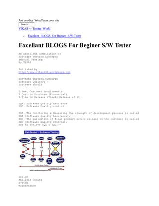
- 1. Just another WordPress.com site Search... VIKAS>> Testing World Excellant BLOGS For Beginer S/W Tester Excellant BLOGS For Beginer S/W Tester An Excellent Compilation of Software Testing Concepts (Manual Testing) By VIKAS Published by http://www.vikas101.wordpress.com SOFTWARE TESTING CONCEPTS Software Quality: - Software should 1.Meet Customer requirements 2.Cost to Purchase (Economical) 3.Time to Release (Timely Release of it) SQA: Software Quality Assurance SQC: Software Quality control SQA: The Monitoring & Measuring the strength of development process is called SQA (Software Quality Assurance). SQC: The Validation of final product before release to the customer is called SQC (Software Quality Control). How to achieve SQA & SQC: - Design Analysis Coding System Maintenance
- 2. Requirements Gathering (BRS) SRS (Software HLD Testing Requirements LLD �s Programming Specifications) Black Box Testing Reviews White Box Testing Testing Software Reviews changes SQA (Verification) SQC (Validation) BRS � Business Requirements Specification SRS � Software Requirements Specification HLD � High-Level Design LLD � Low-Level Design Page 2 BRS: - The BRS defines the requirements of customer to be developed. SRS: - The SRS defines the functional requirements to be developed and the system requirements to be used. Reviews: - A document level testing technique during this review, the responsible people are estimating the completeness & correctness of corresponding document. There are 3 ways i. Walk - through ii. Inspection iii. Peer Review i. Walkthrough - Study a document from 1st line to last line ii. Inspection � Search for a specific issue in a document (Without Intimation). iii. Peer Review � Compare a document with other similar document. Design: - pictorial representation of the project/Software to be developed. HLD: - The HLD documents defined the overall architecture of the system. HLD of a Mail/Chat Client Root `L ``O `GIN MAILING CHATTING Leaf LOGOUT The above overall design is also known as Architectural Design / External Design. Page 3 LLD: - the LLD documents define the internal structure of every module or Functionality USER User ID & Password LOGIN DB Invalid Valid NEXT PAGE LLD of a Login Screen Program: - A set of executable statements is called a program. Software consists of multiple programs. A program consists multiple statements. White Box Testing: - A program level testing technique. In this technique, the responsible people are verifying the internal structure of the corresponding program.
- 3. These White Box Testing techniques are also known as Open Box Testing / Glass Box Testing / Clear Box Testing Black Box Testing: - It is a Software level testing technique. During this test the responsible people are validating external functionality. V � Model: - V stands for Verification & Validation] This model defines the conceptual mapping in between Development stages & testing stages. Page 4 VERIFICATION VALIDATION BRS/CRS/URS User Acceptance Testing Black Box Review Testing Technique SRS System Testing HLD Review Integration Testing LLD�s Coding White Box Testing Techniques Unit Testing In the above model, the separate testing team is available for system testing phase because this phase is Bottleneck Phase to software development process. In remaining stages of testing, the same development people are involved. To decrease project cost. Reviews and Analysis: In general, the software development process starts with requirements gathering & analysis. In this phase, the Business Analyst category people develop BRS and SRS. They conduct review on the documents for completeness & correctness. The Business Analyst prepares these questions on BRS / SRS. Page 5 iv. i. i. .v i..i .i .i iv. v. Are they Right Requirements? Are they Complete Requirements? Are they Achievable Requirements? Are they Reasonable Requirements? Are they Testable Requirements? II. Reviews in Design After completion of Analysis & their reviews the designer category people develops HLD & LLD�s are conducts reviews on the documents for completeness & correctness. The designers prepare these questions on the HLD & LLD�s. iv. i.
- 4. i. .v i..i .i .i iv. v. Are they understandable designs? Are they meeting the right requirements? Are they complete designs? Are they followable designs? Are they handling errors? III. Unit Testing: - After completion of design & their reviews, the programmers start coding. In this phase, the programmers prepare programs & then test each program using White Box Testing Techniques. There are 4 White Box Testing Techniques: 1.Basis Path Testing 2.Control Structure testing 3.Program technique Testing 4.Mutation Testing These Techniques are applicable only for Programs. 1.Basis Path Testing: During this test the programmers concentrate on the execution of programs without any runtime errors. To conduct this test, the corresponding programmer follows the below approach. Write a program with respect to LLD (Low Level Design) Draw a flow graph for that program. Calculate cyclomatic complexity. Runt that program more than one time to cover all executable areas. Page 6 Eg: If (?) Condition T F else Cyclomatic Complexity = 2(1+1) One should run the above program 2 times to cover all executable areas. A programmer gets confidence that a program is running only when the cyclomatic complexity is reached in running the programs designed. NOTE: The above program should be run 2 times ° One time to check whether if condition is satisfied or not ° Next time to check whether the else condition is satisfied or not, without any runtime errors. 2. Control Structure Testing: During this test, the corresponding programmer concentrates on correctness of program execution in this test, they verify every statements of program execution. In this test, they verify every statements input state & Output state. Eg: Debugging 3. Program Technique Testing: During this test, the programmers concentrate on the execution speed of a program. If the execution speed is not reasonable, then programmers perform changes in the structure of the program without disturbing
- 5. functionality of the program. A B Eg: Swapping Program i. c=a; a=c+b; Page 7 a=b; b=a-c; b=c; c=b-a More Memory usage for fast running Low memory usage for fast running 4. Mutation Testing: During this test, the corresponding programmers estimate completeness & correctness of a program testing. Eg: Tests Tests Tests Change Change Passed Passed Failed (Complete Testing) (In Complete Testing) IV. Integration Testing: After completion of dependent programs development & Unit testing, the programmers interconnect them. Then the programmers verify the interconnection of the programs in any one of the below four ways. 1. Top-Down Approach 2. Bottom-Up Approach 3. Hybrid Approach 4. System Approach 1.Top-Down Approach: The interconnection of the main program & some sub-programs is called the Top-Down Approach. Programmers use temporary programs called stubs instead of sub-programs, which are under construction. The other name for stubs is �Called Programs�. A stub returns the control to the main program. Eg: MAIN STUB SUB 1 SUB 2 (Under Construction) * In this Approach first Parent Modules are developed * After that Child Modules are developed * Then interconnect Parent & Child Modules. Page 8 * In the interconnection process is there any the sub-module is under construction then the developers create temporary program Instead of sub modules that is called �Stub�. 2.Bottom � Up Approach: The interconnection of internal sub-programs without using main programs is called the bottom up approach. In this approach, programmers use a temporary program instead of main program, which is under construction. The temporary program is called �Driver� or �Calling Program�. Eg: MAIN (Under Construction) DRIVER SUB 1 SUB 2 *In this approach first Child Modules are developed. * After that parent modules are developed * Then interconnect Child Modules with Parent Modules. * In the interconnection Process is there any main module is under
- 6. construction then the developers create temporary program that is called �Driver�. Difference Between STUB & DRIVER: STUB DRIVER 1.Temporary Program is used instead of 1.Temporary Program used instead of main Sub-Programs, which are under Program, which is under construction Construction 2.Used in Top � Down approach 2.Used in Bottom � Up approach 3.Other name is �Called Programs� 3.Other name is �Calling programs� 4.Returns Control to the main program. Page 9 3.Hybrid Approach: Also known as �Sandwich approach�, this is a combination of the Process Top-Down Approach & Bottom-Up Approaches. Eg: MAIN (Under Construction) DRIVER SUB 1 STUB (Under Construction) SUB 2 SUB 3 4.System Approach: It is also known as �Big Bang Approach�. From this approach, the programmers interconnect programs after completion of all programs development & unit Testing. Build: A finally integrated set of all programs is called a �Build� or AUT (Application Under Testing). 5.System Testing: - After completion of integration testing, a separate testing team receives a software build from the development team. This team a set of block box testing techniques to validate that software build the system testing is satisfied into 3 categories. Page 10 1. Usability testing 2. Functional Testing 3. Non � Functional Testing 1.Usability Testing: In general, the separate testing team starts test execution with usability testing. During this test, the team concentrates on user-friendliness of the software build screens. The usability testing consists of 2 sub tests. a) User � Interface Testing b) Manuals Support Testing a) User - interface Testing: - In User Interface Testing software build is tested for ‰ Ease of use (Understandability) ‰ Look & Feel (Attractiveness) ‰ Speed in Interface (Short navigations) These are applied on every screen in the software build. b) Manuals Support Testing: - Also known as �Help - documents testing�. During this test, the testing team concentrates on correctness & completeness of Help � Documents / User Manuals.
- 7. NOTE: In general, the testing team conducts User- interface testing & then conducts functional & non�Functional Tests. All the end of testing process, the testing team concentrates on Manuals Support Testing Receive build from development team. User Interface Testing (Usability Testing) Functional & Non � Functional Testing Manuals Support Testing 2. Functional Testing: Page 11 A Moderator testing level during which the testing team concentrates on customer requirements interms of functionality. During this test, the testing team applies below sub-tests on the software build. i) Functionality Testing ii) Sanitation Testing i) Functionality Testing: - During this test, the testing team concentrates on correctness of every functionality with respect to requirements. In this test, the testing team follows the below coverage. ‹ GUI Coverage / Behavioral Coverage (Changes in Properties of Objects in Screen) ‹ Error Handling Coverage (Preventing incorrect Operations) ‹ Input Domain Coverage (Taking correct size & type of Inputs) ‹ Manipulations Coverage (Returning correct output) ‹ Backend Coverage (The Impact of front-end screens operations on backend tables) ‹ Order of functionalities Coverage ii) Sanitation testing: - This is also known as �Garbage Testing�. During this test, the testing team identifies extra functionalities in the software build with respect to customer requirements. 3. Non-Functionality Testing: A complex level in system testing during which the testing team concentrates on extra characteristics of the software. i. Recovery Testing ii. Compatibility Testing iii. Configuration Testing iv. Inter system Testing v. Installation Testing vi. Load Testing vii. Stress Testing viii. Data Volume Testing Page 12 ix. Parallel Testing i. Recovery Testing: - It is also known as �Reliability Testing�. During this testing team validates that whether the software build changes from abnormal mode to normal mode. (Abnormal) Back up & Recovery Procedures ii) Compatibility Testing: -
- 8. Normal Also Known as �Portability Testing�. During this test, the testing team validates whether the software build is running on customer expected platforms or not? Platforms are Operating Systems, Compilers, Browsers & Other system software. iii) Configuration Testing: - It is also known as �Hardware compatibility test�. During this test, the testing team validates whether the software the software build is supporting different technologies, hardware devices or not? Eg: Different printer technologies, various network technologies, etc. iv) Inter System Testing: It is also known �END � TO � END� Testing. During this test, the team validates whether the software build is co-existent with other software to share common resources or not? Eg: Front-end Backend Accounts S/W A/c No. Sharing of Resources Page 13 Loans S/W Front-end Backend v) Installation Testing: - S/W Build + Install Supported S/W Customer Expected Configuration Computer ‰ Set UP ‰Easy Installation ‰Occupied Space Below are the 3 key factors of installation ‰ Setup Program Execution ‰ Easy Installation of the Programs ‰ Occupied Space vi) Load Testing: - The execution of our software build in a customer expected configuration environment under customer expected load to estimate performance is called �Load Testing or Scale Testing�. The load or scale means that the no. of concurrent users access our application build. Eg: User SERVER Client 1 Client 2 *How make time is taken by the server to respond to each of the clients. vii) Stress Testing: - The execution of our software build in customer expected configured environment under various levels of load to estimate reliability is called �stress testing�. Eg: Client 1 Connectivity Level
- 9. Page 14 SERVER Client 3 Reliability * In this there will be many users. viii) Data Volume Testing: - During this test, the testing team estimates the peak limit of data handled by our software build. Eg: Account Software A/C S/W Front end Back end NOTE: This should be in terminology of customer. ix) Parallel Testing: - It is also known as �Comparative Testing� or �Competitive Testing�. During this test, the testing team is comparing the recent software build with previous versions of the software build or with the competitive software in market to estimate competitiveness. This testing is only applicable to software products. 5. User Acceptance Testing: After completion of system testing & their modifications, the project management concentrates on User acceptance testing to collect feedback. These are two ways to conduct user acceptance testing. They are - testing and â - Testing. - Testing â - Testing 1. By real customers 1. By Model Customers 2. In development site 2. In Model Customer site 3. Suitable for Applications 3. Suitable for Products 6. Release & Maintenance: - Page 15 After completion of user acceptance testing and their modifications, the project management concentrates on the release team. This release team consists of a few programmers few test engineers & some hardware engineers. a) Port Testing b) Test Software Changes a) Port Testing: - The corresponding release team conducts port testing on the customer site. During this test, the release team observes the below factors. V Compact Installation V Overall Functionality V Input device handling V Output device handling (Like Monitor, Printer, etc) V Secondary storage device handling (Like Floppy disk, CD-Rom, etc) V Operating System with other handling V Co � Execution with other software. After comparison of Port testing, the responsible release team Provides required training sessions to the customer. Side people & get back to the organization. b) Test Software Changes: - During the utilization of the released software, the customer side people send change requests (CR) to the organization. To receive these CRs, the organization establishes a special team along with a few programmers, some test engineers & a project manages category person. This team is called �Change
- 10. Control Board� (CCB). Change Requests Enhancement Missed Defects Impact Analysis Impact Analysis Perform Software Changes Perform Software changes Page 16 Test Software Changes Test Software Changes Improve Capability of Testing Team Testing Phase Responsibility Testing Techniques 1. Reviews in Analysis Business Analyst Walk - through Inspection & peer - review 2. Reviews in Design Designer Walk - through Inspection & Peer - review 3. Unit Testing Programmers White Box Testing techniques 4. Integration Testing Programmers Top - Down, Bottom - up, Hybrid & System 5. System Testing Test - Engineers Black Box Testing Techniques 6. User Acceptance Testing Real Customers (or) Alpha (á) Testing & Model Customers Beta (â) Testing 7. Release Release Team Port Testing 8.Test Software Changes CCB In Maintenance (Change Control Board) Regression Testing 7. Ad-hoc Testing: - In general, every testing team conducts planned testing, but testing team adopts informal testing sometimes due to some challenges or risks. Eg: Lack of time, lack of resources, lack of team size, lack of skill, etc. This informal testing is also known as Ad-hoc testing. There are different styles in Ad-hoc testing. a) Monkey Testing Page 17 b) Buddy Testing c) Exploratory Testing d) Pair Testing e) Defect Seeding / Debugging a) Monkey Testing: - Due to lack of time, the testing team concentrates on some of the main activities in the software build for testing. This style of testing is known as �Monkey testing� or �Chimpanzee testing� or �Gorilla testing�. b) Buddy Testing: - Due to lack of time, the management groups programmers & testers as �Buddies�. Every buddy group consists of programmers & testers. Eg: 1:1 (or) 2:1 (or) 3:1 (preferable) c) Exploratory Testing: - Due to lack of proper documentation of the software being built, the test engineers depend on past experience, discuss with others, browse the Internet or Operate similar projects and contact customer side people if possible. This style of testing is called �Exploratory Testing�. d) Pair Testing: - Due to lack of knowledge on project domain the management groups a senior tester & a Junior Programmers are developed and conducted testing, these all are called Pair testing. e) Defect Sending: -
- 11. To estimate the efficiency of test engineers, the programmers add some bugs to the build. This task is called defect seeding / debugging. Testing Terminology: - 1. Test Strategy 2. Test Plan 3. Test Case 4. Test Log 5. Error, Defect & Bug 6. Summary Report 7. Test Bed Page 18 8. Test Suite 9. Testing Policy 10. Testing Process 11. Testing Standard 12. Testing Measurement 1. Test Strategy: - It is a Company level document and developed by Quality Analyst. A testing strategy defines Testing approach followed by testing team (or) (An approach to be followed by testing team in testing a build). 2. Test Plan: - A schedule to be followed by testing team in testing. 3. Test Case: - A test condition to be applied on software build. 4.Test Log: A result of test case interms of passed / failed. 5. Error, Defect & Bug: - A mistake in coding is called error. This error detected by tester during testing is called defect or issue. This defect or issue accepted by programmers to resolve is called bug. 6. Summary Report: - Defines work progress Eg: Daily reports, weekly reports and Monthly report. 7. Test Bed: - Total Testing, information and test environment is called as test bed. 8. Test Suite: - All the combination of all the different test cases is called as test suite. 9. Testing Policy: - It is a Company level Document and developed by Quality Control Document and developed by quality control people (almost Management). The testing policy defines Testing Objective. Page 19 10. Testing Process: - Proper Planning before starts testing 11. Testing standard: - 1 defect per 250 LOC (Lines of Code) 1 defect per 10 FP (Functional Points) (Eg: No. Of Screens, (or) no. Of forms, (or) no. Of reports, no. Of queries etc.) 12. Testing Measurement: - QAM (Quality Assessment Measurements) TMM (Test Management Measurements) PCM (Process Capacity Measurements) NOTE: The other name for test case document is functional test plan VIII. Regression Testing: - The Re-Execution of selected tests on modified build to estimate
- 12. completeness and correctness of modification is called Regression Testing. Related passed Test Tests Remaining Tests Build Failed Tests Modified Build Passed Defect Report Failed Developers Testing Process: - Test Initiation Test Planning Test Design Test Execution Test Closure Test Reporting Page 20 DEVELOPMENT PROCESS V/S TESTING PROCESS: - Gathering Requirements (BRS) Analysis (SRS) Design (HLD, LLD�s) Test Initiation Coding & Unit Testing Test Planning Integration Testing Test Design Test Execution Test Reporting Test Closure I. Test Initiation: - In general, the system testing process starts with test initiation. In this stage, the project Manager category people selects reasonable tests to be applied. After selecting reasonable tests, the manager prepares �Test Strategy Document� also known as �Test Methodology�. SRS By Project Manager / Test Manager Test Initiation Strategy Page 21 Risks Output Document Input The Test strategy document consists of the below documents 1. Scope & Objective 2. Business Issues 3. Approach 4. Roles & Responsibilities 5. Communication & Status Reporting 6. Testing Measurements & Metrics 7. Change & Configuration Management 8. Test Automation & Testing Tools 9. Defect Reporting 10. Risks & Assumptions 11. Training Plan
- 13. 1.Scope/Objective: The Purpose of testing in this project. 2. Business Issues: Budget allocation for testing. As per US norms 100%‰ Project Cost 64% 36% Development Testing & Maintenance 3. Approach: Selected list of reasonable tests with respect to requirements in project, scope of the requirements & risks involved in the project. 4. Roles & Responsibilities: The names of jobs in testing team and their responsibilities. 5. Communication & Status Reporting: The required negotiation in between every 2 jobs in testing team. 6. Testing Measurements & Metrics: A list of quality, Management & capability measurements. 7. Change & Configuration Management: Maintenance of deliverables for future reference. Eg: Test cases, test Log, defect Reports and other summary report. 8. Test Automation & Testing Tools: The importance of Automation in corresponding project testing & available testing tools in the organization. 9. Defect Reporting & Tracking: Required negotiation in between testing team & Development team in test reporting. Page 22 10. Risks & Assumptions: A list of analyzed risks & solutions to overcome. 11. Training Plan: The required number of training issue or a testing topic there are 15 topics as maximum to define quality software. Test Factors: Test factor means a testing issue or a testing topic. There are 15 topics as maximum to define quality software. 1. Authorization: software, which allows valid users & prevents invalid users. 2. Access Control: Authorities of valid users to use specific functionality 3. Audit Trail: Maintains metadata about user operations. 4. Data Integrity: Taking correct size & 5. Correctness: Returning correct outputs 6. Continuity of processing: integration of internal functionalities. 7.Coupling: Co � Existence with other softwares to share common resources 8.Ease of use: User- friendly screens 9.Ease of Operations: Installation, un-installation, downloading 10.Portable: Run on different platforms. 11.Performance: Speed of processing 12.Reliability: Recovery from abnormal situations 13.Service levels: Order of functionalities to service to customer 14.Maintainable: Serviceable to customers� long time. 15.Methodology: Whether the testing team is following Quality standards or not while testing. Case Study # 1 CEO -------------‰ Quality Software Project Manager/Test Manger -------------‰ Test Factors Test Lead -------------‰ Testing Techniques Test Engineer -------------‰ Test Cases
- 14. Test Factor v/s Testing Techniques 1. Authorization : Security Testing 2. Access Control : Security Testing 3. Audit Trail : Functionality Testing 4. Data Integrity : Functionality Testing 5. Correctness : Functionality Testing 6. Continuity of Processing : Integration Testing (By Developers) 7. Coupling : Intersystem Testing 8. Ease of use : User interface, Manual Support Testing 9. Ease of Operation : Installation Testing Page 23 10.Portable : Compatibility & Configuration Testing 11.Performance : Load, Stress & Data Volume Testing 12.Reliability : Recovery Testing (Single User Level) Stress Testing (Multi User Level) 13.Service levels : Functionality Testing 14.Maintenable : Compliance Testing 15.Methodology : Compliance Testing (Whether standards are maintained by team) Case Study # 2 Total 15 � factors -4 - (Requirements) 11 +2 - (Scope of Requirements) 13 -4 - (Risks) 9 - (Finalized) In the above example nine factors are finalized to be applied in the system testing of a project. II. Test Planning: After selection of reasonable tests to be applied the project manager or Test Manager releases test strategy documents with all required details to the test lead. The test lead concentrates on test plans preparation. In this stage, the test lead prepares one system test plan and multiple detailed test plans. Test Strategy Team Formation Development Documents (BRS, SRS) Development Plan Identify Risks Prepare Test plans Review Test Plans Test Plan a) Team Formation: - Page 24 In general, the test planning process starts with testing team formation. In this phase, the test lead depends upon the below factors. -------------‰ Project Size -------------‰ Availability of test engineers -------------‰ Test Duration -------------‰ Availability of test environment resources. b) Identify Risks: - After completion of reasonable testing team formation, the test lead concentrates on risks at the team level. Eg:
- 15. Risk 1: Lack of knowledge of testing team on domain. Risk 2: Lack of time Risk 3: Lack of resources Risk 4: Lack of documentation Risk 5: Delays in delivery Risk 6: Lack of rigorous development process Risk 7: lack of Communication c) Prepare Test Plans: - After testing team formation and risks analysis the test lead prepares test plan documents. Format: 1. Test Plan ID: The identification no. or name. 2. Instructions: About the project 3. Test Items: Name of modules or functionalities or services. 4. Feature to be tested: The names of modules which are selected for testing Eg: a, b, c Modules are all to be tested. 5. Features not to be tested: The names of remaining tested modules. Eg: V1‰ V2 = V1+Some extra modules (These are to be tested) 6. Approach: The selected list of selecting techniques with respect to test Strategy (selected by Project Manager) 7. Test Environment: Required Hardware & Software to apply the selected test on specified features. Eg: a, b, c, d cd ----------‰ UI ST CI (Features) MI LT CI Page 25 FI 8. Entry criteria: ‰ Prepare complete & correctness ‰ Establish Test environment ‰ Receive stable build from developers. 9. Suspension criteria: ‰ Test environment is nor supporting ‰ Show stopper defect occurred (without resolving the problem, we cannot start testing) ‰ Pending defects are more (Quality gap) 10. Exit Criteria: ‰ All modules tested ‰ Meet the duration ‰ All major bugs resolved 11. Test Deliverables: The names of test documents to be prepared by test Engineers. Eg: ‰ Test Scenarios ‰ Test Case Documents ‰ Test logs ‰ Defect Reports ‰ Summary reports etc. 12. Staff & Training needs: The names of selected test engineers and required training sessions for them. 13. Responsibilities: The mapping in between test engineers and their available testing area. 14. Schedule: Dates & Time 15. Risks & Assumptions: List of previously analyzed risks & assumptions 16. Approvals: The signature of test lead and Project Manager. d) Review Test Plan:
- 16. After completion of preparation of test documents the test lead (TL) conducts a review meeting to check the completeness & correctness of the documents. Test Plan (1) ‰ Requirements oriented review ‰ Testing techniques oriented review ‰ Risks oriented review Page 26 After completion of the above review meeting, the test lead provides training sessions to selected test engineers. II. Test Training: - In these training sessions, the total testing team is responsible to understand the complete project requirements. III. Test Design: After completion of required no. of training sessions, the responsible test engineers concentrate on test cases selection. Every test case defines a unit unique test conditions to validate the software build in terms of usability, functional, non-functional aspects. These are 3 methods to prepare test cases 1. Functional & System specification based test case design 2. Use cases based test case design 3. Application/Prototype based test case design. 1. Functional and System specification based test case design: In general, the test engineers prepare maximum test case depending upon functional & system specifications in SRS. BRS Prepare SRS Test Cases HLD & LLD�s Coding (Build) - AUT From the above diagram, test engineers prepare test cases depending upon the SRS through the below mentioned approach Step 1: Collect responsible functional & system specification including dependents Step 2: Select one specification from that collected list. Step 3: Study the specification in terms of base state, inputs, outputs, normal flow, Page 27 end state, alternative flows and executions. Step 4: Prepare test case titles/test scenarios with respect to above studied info. Step 5: Review the test case titles for completeness & Correctness. Step 6: Prepare test case document. Step 7: Go to Step2 until all responsible specifications are studied. Functional Specification 1: - A login process allows user ID & password to authorize users. From customer requirements user ID takes 9-numarics in lower case from 4 to 16 characters long. The password object takes alphabets in lower case from 4 to 8 characters long. Prepare test case titles or scenario. Test Case Title 1: Verify user ID Boundary Value Analysis (Size) Equivalence Class partition (Type) Min-1 ----- 3 Characters -------Fail Valid Invalid Min ------- 4 Characters -------Pass a - z A - Z Min+1---- 5 Characters -------Pass 0 � 9 Special Chars. Max-1 ---15 Characters ------ Pass Blank field.
- 17. Max -----16 Characters ------ Pass Max+1- 17 Characters ------ Fail Test case Title 2: Verify password Boundary Value Analysis (Size) Equivalence Class Partition (Type) Min-1 ----- 3 Characters ---- Fail Valid Invalid Min ------- 4 Characters ---- Pass a � z A - Z Min+1 --- 5 Characters ---- Pass 0 - 9 Max-1---- 7 Characters ---- Pass Special Chars Max ----- 8 Characters ---- Pass Blank Field Max+1 � 9 Characters ---- Fail Test Case Title 3: Verify Login Information User ID Password Criteria Valid Value Valid Value Pass Valid Value Invalid Value Fail Page 28 Invalid Value Valid Value Fail Blank Value Valid Value Fail Valid Value Blank Value Fail Invalid Value Blank Value Fail Blank Value Invalid Value Fail Blank Value Blank Value Fail Functional specification 2: In an insurance application, can apply for different types of policies. From customer requirements, the system asks age, when a user selects type insurance. The age value should be >17 years and should be 10 months then the interest is also >10% Page 40 Prepare test case titles: Document 1: 1. Test case ID: - TC_FD_Thiru_06th Jan_1 2. Test case Name: - Verify Depositor Name 3. Test Suite ID: - TS_FD 4. Priority: - P0 5. Test Setup: - Depositor Name is taking Values 6. Data Matrix: I/P Object ECP (Type) Valid Invalid BVA (Size) Min Max Depositor Name a �z a� z without (with init init cap cap) A � Z, 0 � 9 Special Characters Blank field 1 chars 256 chars Document 2: 1. Test case ID: - TC_FD_Thiru_06th Jan_2 2. Test case Name: - Verify amount 3. Test Suite Id: - TS_FD 4. Priority: P0 5. Test Setup: - Amount field is taking values. 6. Data Matrix: - I/P Object ECP (Type) Valid Invalid BVA (Size)
- 18. Min Max Depositor Name amount 0 -9 a� z A � Z, Special Characters Blank field 1500 1,00,000 Document 3: - 1. Test case ID: - TC_FD_Thiru_06th Jan_3 2. Test case Name: - Verify Tenure 3. Test Suite Id: - TS_FD 4. Priority: P0 Page 41 5. Test Setup: - Tenure is taking values. 6. Data Matrix: - I/P Object ECP (Type) Valid Invalid BVA (Size) Min Max Interest 0 -9 a� z A � Z, Special Characters Blank field 1month 12 months Document 4: - 1. Test case ID: - TC_FD_Thiru_06th Jan_4 2. Test case Name: - Verify Interest 3. Test Suite Id: - TS_FD 4. Priority: P0 5. Test Setup: - Interest is taking values. 6. Data Matrix: - I/P Object ECP (Type) Valid Invalid BVA (Size) Min Max Depositor Name 0 - 9 , a � z 0 - 9 A � Z, with Special One Characters decimal Blank field 0 �9 with more than one decimal 0.1% 100% Document 5: - 1. Test case ID: - Tc_Login_Thiru_06th Jan_5 2. Teat case name: - Verify Fixed Deposit Operation 3. Test Suite ID: - TS_FD 4. Priority: - P0 5. Test setup: - Valid & Invalid Values available in hand. 6. Test Procedure: - Step no. Action I/P Required Expected
- 19. 1 Connect to Bank Server 2 Select Fixed Deposit Valid EMP ID None Menu appears Fixed deposit Page 42 Option in Menu 3 Enter Field values & Click OK Valid name & amount All are valid Any one valid Any on blank From form opened Next Page Error Message ------do------- -----do-------- Document 6: - 1. Test case ID: - Tc_Login_Thiru_06th Jan_6 2. Teat case name: - Verify existing rule 3. Test Suite ID: - TS_FD 4. Priority: - P0 5. Test setup: - Valid & Invalid Values are available in hand w.r.t rule. 6. Test Procedure: - Step no. Action I/P Required Expected 1 Connect to Bank Server 2 Select Fixed Deposit Option in Menu 3 Enter Field values & Click OK Valid EMP ID None Valid name & amount and Tenure > 10 With Interest >10 With Interest <=10 Menu appears Fixed deposit From opened Next Page Next Message Error message ------do------ Use cases based test case design: - In some situations, the testing team converts functional & system specifications in SRS into use cases to maintain complete & correct information. This is possible to outsourcing testing organizations. In this method, test engineers prepare test cases depending on use cases instead of functional & system specifications. BRS Use Cases Page 43
- 20. SRS Test Cases HLD & LLD�s Coding (Build) Use cases are more elaborate than functional & System specifications in SRS. Every use case follows a common format. Use Case Format: 1. Use case Id: Unique no. or name for future reference. 2. Use case description: The summary of use case functionality 3. Actors: The input requirements of corresponding functionality 4. Pre-Conditions: Necessary tasks before starting this functionality 5. Actions: A step-by-step procedure with required inputs and expected outputs 6. Post-Conditions: Necessary tasks after completion of this functionality 7. Alternative flows: a step-by-step alternative procedure if possible. 8. Flow Graph: Diagrammatic notation to understand functionality. 9. Prototype: Model screen to understand functionality 10.Exceptions or Rules: The possible conditions in that functionality if available. After completion of all reasonable use cases development with complete & correct information, the separate testing team concentrates on test case selection & documentation. 1. Collect required use cases and their dependencies. 2. Select on use case from the list 3. Study the use case in terms of inputs, base state, end state, outputs, normal flow, alternative flow and Rules. 4. Prepare test vase titles or scenarios. 5. Review the titles for completeness & correctness. 6. Document the test cases with complete information. 7. Go to step 2 until all collected use cases are studied. NOTE: Page 44 1. The functional & System specification based test case design is suitable for general organizations because subject exploring is possible in general organizations. The use cases based test case design is suitable for testing outsourcing companies because subject exploring is critical for them. SRS Test Cases General Organizations SRS Use Cases Test Cases Outsourcing Organizations 2. First method is suitable for applications where as the second method is more suitable for product based organizations. 3. Application or user interface based test case design: - It is not an alternative method to the previous two test case design methods. In this method, test engineers concentrate on usability test cases preparation depending on the common interface rules and the psychological level of customer side people. Example Usability Test cases: - Test Case 1: Verify spelling in every screen Test Case 2: Verify color uniqueness in screens Test Case 3: Verify font uniqueness in screens Test Case 4: Verify size uniqueness in every screen Test Case 5: Verify initcap Test Case 6: Verify alignment Test Case 7: Verify name spacing uniqueness in every screen.
- 21. Test Case 8: Verify space uniqueness in between controls. Test Case 9: Verify contrast in between controls. Test Case10: Verify related Objects grouping Test Case11: Verify Group edges/boundaries Test Case12: Verify positions of multiple data objects in screens. Test Case13: Verify scroll bars of screens. Test Case14: Verify the correctness of image icons Test Case15: Verify tool tips. Test Case16: Verify full forms of shortcuts (Eg: Abbreviations) Test Case17: Verify shortcut keys in keyboard. Test Case18: Verify formats. Test Case19: Verify help documents. Page 45 Review Test Cases: - After completion of selection of all reasonable test cases, test lead conducts a final review, test lead concentrates on those test cases. In this review test lead depends upon the test factors. V Requirements oriented test cases review V Testing techniques oriented test cases review. After completion of reviews & their modifications, testing team concentrates on test execution. IV Test Execution: - After completion of test design & review, the testing team conducts a formal meeting with development team. In this meeting, the development & testing teams concentrate on. i. Build Release process ii. Build version process iii. Defect tracking system SERVER INTERNET Development Testing Builds Documents Documents Configuration Repository (C.R) Development Environment Customer Environment Testing Environment From the above model, the testing people downloads build from common repository in server with permissions. In the common repository development people maintains old build coding & modified build coding. To distinguished old build & modified build, the development team assigns unique version no. s to that Page 46 builds. For this build version control, the development team uses version control tools. (VSS � Visual Source Safe) Development team will send release note to testing team for every modified build. This release note provides information about changes in build. Levels of Test Execution: - Development Testing (Initial Build) Level 0 (Sanity) (Stable Build) Fixing Level 1(Comprehensive/Real (Defect Report) Testing)
- 22. Resolving (Modified Build) Level 2 (Regression Testing) Level 3 (Final Regression) 3. Levels of Test Execution Vs Test Cases: - Level 0: ‰ P0 Test Cases (Basic Functionality) Level 1: ‰ All P0, P1 & P2 Test Cases Level 2: ‰ Selected P0, P1 & P2 Test Cases with respect to Modifications Level 3: ‰ Selected P0, P1 & P2 Test Cases with respect to bug density. NOTE: 1. P0 priority Test cases indicate functionality testing, P1 priority test cases indicate non-functional testing & P2 test cases indicate usability testing. 2. Level � 0 (Sanity) on initial build Level � 1(Comprehensive) on suitable build. Level � 2(Regression) on modified build Level � 3(Final Regression/Post Mortem) on Master build. (User-Acceptance Testing) on Golden build. Page 47 4. Level 0 (Sanity Testing): After the establishment with required software & Hardware then Testing Team conducts Sanity Testing to estimate Testability of that initial software build. If the initial build is not testable, then the Testing team rejects that build & waits for suitable build to receive from developers. If the build is testable without any functionalities missing then the testing team concentrates on level 1 Real or Comprehensive Testing. In this level 0 Sanity testing, the testing team estimates testability with the help of the below factors. ‰ Understandability ‰ Simplicity ‰ Operatability ‰ Observability ‰ Consistency ‰ Maintainable ‰ Automatable (Optional) ‰ Controllable The combination of the above 8 factors is called testability. These 8 factors coverage on build estimates testability. The level 0 sanity testing is also known as smoke testing or testability testing or tester acceptance testing. Level 1 (Comprehensive Testing): After receiving stable build from developers the testing team concentrates on level 1 or comprehensive testing. In this stage, the testing arranges the dependent test cases as batches, every batch is also known as test suite or test set or test belt or test chain. After creating test batches, the test engineers execute case by case in every batch through manual testing or automated testing. Build Test Cases Execution (By Tester) Manual Testing Build Testing Tool By Tester Automated Testing
- 23. Page 48 During test execution, either in manual or in automation, test engineers purpose test log document. This document consists of three types of entries. ‰ Passed --- all expected values in test case are equal to actual values of build. ‰ Failed --- anyone expected is varying with actual values of build. ‰ Blocked � Test case execution postponed due to incorrect failed functionality Test engineers prepare the above entries in test log for every test case in every test batch. Arrange Test Cases as Queue Skip Execution Manual / Passed Test Batches Blocked Automation Failed Partial Pass / Fail (or) Warning Closed Level 1 (Comprehensive) Test Cycle From the above comprehensive test cycle diagram, the final status of every test case is that: Skip or Passed or Closed Level 2 (Regression Testing): During level 1 comprehensive testing the testing reports mismatches, if any to the development team defects reports. After accepting those defects, the developers perform changes in build coding and releases the modified build with release note. The testing on that modifies build to ensure completeness & correctness of the modifications in the build. Level � 0 Page 49 Level 1 Test Reporting Level 2 Level 3 In Level 2 Regression testing, the test engineers re-execute previously executes test on modified build to ensure modification. The selection of test cases to be re-executed depends upon the release note. Identify resolved defect severity with respect to release with respect to release note of modified build. High Medium Low All P0, All P0, Some P0, All P1, Carefully Selected Some P1, Carefully Selected P1 & Some Some P2, P2 Test Cases P2 Test Cases Test Cases Case 1: If the defect resolved by the development team is of high severity, the test engineers re-execute all P1 & carefully selected P2 Test case. On that modified build with respect to modification specified in release note.
- 24. Case 2: If the defect resolved by the development team is of medium severity, then test engineers. Re-execute all P0, carefully selected P1 & some of P2 Test cases with respect to modification specified in release note. Case 3: If the defect resolved by the development team is low severity, then the test engineers re-execute some P0, some P1 & Some P2 Test cases on that modified build with respect to modifications specified in release note. Case 4: Page 50 If the development team releases modified build due to sudden changes in requirements of customer then the test engineers execute all P0 & carefully selected P2 test cases Test cases on that modified build with respect to changes in requirement. In this level 2 Regression Testing, the testing people user two indicators for modified build: Check �In & Check � Out. Check-In Level 2 Check-Out (Regression Testing) IV. Test Reporting: During level 1 & level 2 test execution, test engineers report mismatches to the development team. In this reporting test engineers uses the format similar to the one given below. Format: 1. Defect ID: A Unique no. or name 2. Description: The summary of the defect including type. 3. Build Version ID: The version no. of build, in this build test engineers deleted defect. 4. Feature: The name of module or functionality in which the test engineers deleted that defect. 5. Test Case Name: The name of failed test case, in this test case execution test engineer detected that defect. 6. Reproducible: Yes/No (Yes � if the defect appears every time during test execution. (No � if the defect rarely appears during test execution)) 7. if no.6 is yes, Attach test procedure. 8. Test Plans, Test Procedure & Snapshots. 9. Severity: The severity of the defect interms of functionality. HIGH/SHOWTOPPER ‰ Important & Urgent. Mandatory to resolve & Unable to continue testing without resolving. MEDIUM/CRITICAL ‰ Important but not urgent. Mandatory to resolve but able to continue testing. LOW/NONCRITICAL ‰ Not Important & Not urgent. May or may not resolve but able to continue testing. Page 51 10. Priority: The Importance of the defect to be resolved with respect to the customer (HIGH/MEDIUM/LOW) 11. Status: New/Re-open New: Reporting first time Re-Open: Reporting same defect 12. Detected by: Thiru.K (Name of the Tester) 13. Detected On: 09th January 2007 (Date of detection & Reporting both should be same. 14.Assigned To: The responsible person at development side to receive this defect
- 25. 15. Suggested fix: (Optional): Suggestions to developers to accept resolve that defect. NOTE: In the above format, test engineers fill all fields, but the �Suggested fix� field is optional & �Priority� field is modifiable by developers. Defect Submission Process: - Project Manger Test Manager Team Lead Test Lead Programmer Test Engineer Long � Scale Organizations Project Manger Test Lead Team Lead Test Engineer Programmer Page 52 Small & Medium Scale Organizations In the above defect submission processed, testing team uses defect tracking softwares. Eg: Test Director, Bugzilla, Quality Center����etc., these softwares use mailing concepts. Defect Life Cycle: NEW Open Rejected Deferred Closed Re-Open New ‰ Open ‰ Closed New ‰ Open ‰ Re-Open ------ ‰ Closed New ‰ Reject ‰ Closed New ‰ Reject ‰ Re-Open ----- ‰ Closed New --------- ‰ Deferred ** What is defect Age? Ans: Time gap between defect reporting & defect closing or deferring. New Closed Defect Age New Deferred Page 53 ** Defect Density: - The average no. of defects found in a module or function is called defect density. Leave a Reply Recent Posts
- 26. Global LOGIC Walk in NAGPUR on 23-24 MARCH 2013 Archives March 2013 Categories Uncategorized Meta Register Log in Entries RSS Comments RSS WordPress.com Create a free website or blog at WordPress.com. The Bueno Theme. Follow Follow “VIKAS>> Testing World” Get every new post delivered to your Inbox. Build a website with WordPress.com