2. 1
Overview
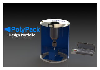
“PolyPack is our innovative solution to creating beautiful, sturdy and environmentally sustainable
packaging.”
The packaging consists of a
soft fibrous interior
transitioning to a hard
plastic shell to provide
twofold protection.
The PolyProducer converts
shredded PET—sourced
from plastic bottles—into an
impact resistant, fibrous
material using a process
inspired by candyfloss
machines.
The PolyPacker uses
heated moulds to
add a rigid,
customisable outer
shell to the
packaging.
Table of contents
Overview
Inspiration and Existing Products
PolyProducer - Initial Prototyping
PolyProducer - Further Prototyping
PolyProducer - Final Iterations
PolyProducer - Final Design
PolyProducer - Exploded View
PolyPacker - Initial Design and Prototyping
PolyPacker - Prototyping
PolyPacker - Further testing
PolyPacker - Final Design
Product Analysis
Packaging Analysis
Presentation Drawing
3. 2
Inspiration & Existing Products
Candy floss machines : the inspiration for the raw material Packaging inspiration
Candyfloss machines: The process of
producing candyfloss is very simple: sugar
is inserted into a spinning central pod. As it
melts, it is flung out of small holes to
create thin fibres. The raw material can be
sugar, boiled sweets, Our concept was to
recreate this using recycled plastic as the
raw material
Polyfloss fibres: Fi-
bres seen online were
rough and unappeal-
ing—this may be im-
proved with parame-
ter optimisation
Housing insulation: More sophisticated
plastic fibres are used in insulation,
suggesting this floss material may have
insulation properties
Sanguine perfume
bottle: packaging
design is often a major
selling point of high
end perfume
Prior art: This idea had already been
exploited by a firm called Polyfloss. They
use PP to make fibres which are used for
craft purposes. We believed this could be
applied in a more practical setting
Existing applica-
tions: often use
hot plates to form
hard layers from
the flossy materi-
al
Existing Polyfloss machine: designed mainly
for aesthetic purposes and an art/craft
setting. This design could be improved for an
industrial setting
It was suggested that the combinations of soft interior, hard
shell and insulation properties could be utilised in packaging,
to reduce the environmental impact of current solutions such
as EPS
Original candy floss patent:
Existing candyfloss machines can
be seen in patents for inspiration:
-Central pod contains rows of
holes to increase production rate
-Heated with elements using
brushes and slip rings because
the bowl rotates
-Opening required in bowl to
allow material to be inserted
Apple: known for making its
packaging “part of the expe-
rience” of purchasing an Ap-
ple product
Devotion ring box:
Jewellery is a high-end
product focussed highly on
fashion and aesthetics
Graze delivery box:
an increasing number
of firms operate
online only and
packaging forms a key
part of their brand
management
Coke bottle:
packaging has
the ability to
become an
iconic part of a
brands identity
Equilateral soap:
using shape to
convey brand
identity
Asylum CD cover: using
texture to draw attention
Nike air: novel material
used to give brand
identity and draw
attention
Colier sparkling wine:
make opening the
product a “grand
reveal” to add to
enjoyment
4. 2
PolyProducer - Initial Prototyping
What is the PolyProducer?
Once we had decided to pursue the idea of
transforming ‘candyfloss-like’ PET into packaging it
was clear that the first crucial stage would be to
work out how to produce the floss material.
Research into existing candyfloss machines
revealed that there are two basic components : a
perforated spinning container and a heat source.
This page details the first steps we took to produce
such a machine which shall henceforth be
referenced as the “PolyProducer”. It was decided
that we would produce our own machine because
existing candyfloss machines would not be able to
reach the 260°C melting temperature of PET , they
were very costly and we wished to redesign them
for an industrial context.
First Sketches
Heat gun used as
the heat source
Contains shredded PET
Electric drill used
to provide the
rotational motion
Cable ties used to
attach to frame
Two steel bowls
welded together
Large hole for
shredded PET
Small holes to
allow extrusion of
PETInserted into drill
Large enclosure
surrounds
everything
Vacuum formed
rounded base
Acrylic sheet
or cardboard
First Prototype
Tried pre-heating
bowl without
spinning but resulted
in one spot getting
too hot
Bowl welded slightly
off centre so
vibrations occurred
Observation window got
too hot and started
to deform (ABS)
A single heat gun was not
heating the PET sufficiently
Stable platform
for drill and heat
gun
Produced our first fibres! - This
proved that our method could
work and now just needed
improvement
Decided that cardboard
would be suitable for the
shield
Holes drilled in
bowl using a
milling machine
Thin fibres showed that
the hole sizing in the bowl
was correct
Sheet steel rolled and spot welded
rather than a second bowl
Addition of a lid
A lid was added
to retain heat
A thick acrylic viewing window was
used because temperatures were
increasing
Concrete blocks were
used to restrain vibrations
The additional heat
retention allowed the PET
to melt and form floss
Some floss melted
onto the heat gun
The floss had not cooled when it
struck the walls, so bonded into
layers
Air-cooled floss had the
properties we desired
Second Prototype
New larger enclosure to allow air-
cooling of floss
Heat gun mounted above
for more direct heating
Vibrations broke the first
heat gun, so made a
separate frame
Fine fibres and no longer melting
together
Folded over to retain
more heat
Need larger
quantities
3
5. 2
PolyProducer - Further Prototyping
Parameter optimization
Once the PolyProducer was reliably producing floss,
it was time to optimise parameters. The diagram on
the right shows how the rotational velocity of the
pod affects the force exerted on the fibres.
Rotational velocity was easy to adjust using the
speed control on the drill. The heat gun only had
two settings and so heat was controlled by raising
and lowering the heat gun relative to the pod.
More holes
Initially, the steel sheet was only
added to prevent spillage. However,
it soon became apparent that the
molten PET was climbing up the
walls. Therefore we were able to
vastly increase the floss production
rate by adding 7 more rows of holes.
Heat gun stand
Relocating the heat gun prevents
the floss hitting it; increases the
temperature in the bowl; separates
it from vibrations and decreases the
start-up time. However, the stand
caught floss before it had fully air
cooled. This should be avoided in
the final product.
Speed Result
Too low No extrusion
Too high
Waste of energy and
damage to fibres
Heat Result
Too low No extrusion
Too high
Dangerous burning of
PET
Heat gun
adjustment
Regularly adjusting the heat gun
meant that it was not always
securely fastened. In one test, the
heat gun came loose and hit the
spinning pod. This broke the weld
at the bottom of the pod and
demonstrated the importance of
rigidity in the final design.
PET shredding
For the first tests we cut up
PET bottles by hand using
scissors. However, clearly
this would not scale up for
an industrial machine.
Therefore, we purchased a
garden shredder which
quickly tears through PET
bottles and reduces them to
chips.
Hole sizing
The hole size was originally set as the
smallest centre drill in the workshop
which could withstand drilling into
stainless steel (the bottom section).
There was concern that these holes
would be too large for fine fibres.
However, as the photo and sketch show,
what actually happens is that the PET
initially extrudes thickly but is then
pulled out into thin fibres by the
centrifugal force. This meant that
hole sizing was not a parameter
which needed changing.
Rows of holes added using the mill
Rotational velocity affects
force on PET
Much larger quantities of floss produced
Getting wrapped around the stand
Not air-cooled therefore bonds together
Proposed solution: suspend heat
gun from the outer casing.
Rotates to allow PET to be added
Heat gun very close to spinning pod Broken pod Dislodged heat gun
Initial extrusion is thick
Sequence of floss formation
1. 2. 3.
4. 5. 6.
Further extrusion results in more force
Necking occurs Snapping releases floss
Garden shredder used for
PET
Shredded PET 4
6. 5
PolyProducer - Final Iterations
Before adding the constraints of what could feasibly be made within budget, in the time frame
and in the IFM and CUED workshops, it was decided that we would use CAD to design what the
PolyProducer would ideally look like. This freedom from constraints allowed us to create the eye
-catching concept shown below. We were then able to adapt this to be feasible.
Issues with concept
The concept on the left was printed onto a large poster which acted as a visual aid and allowed us to discuss how we
would realistically manufacture the PolyPack machine. Each component was considered separately with regards to its
ease of manufacture and its functionality. The results of this discussion are detailed below.
This discussion ended in an agreement as to how to build the final product for the design show. CAD was used to dimension these ideas and
enable us to more carefully think about how all the parts fit together. The CAD is shown below.
Clear domed
lid to observe
floss making
Hopper for
feeding in
shredded PET
Side window to allow
observation of floss making
at production level
Tube with
suction to collect floss
PolyPacker
machine
(discussed later in
portfolio)
Floss
collection bin
800mm diameter to allow air cooling
Houses motor for spinning
pod
Mounting plate
bolted to
factory floor
The largest vacuum
former could not
accommodate the
800mm diameter
required for the
domed lid.
This method of adding PET
is not well suited to
precision placement in the
small, hot, spinning pod.
The indented profile would does not add functionality
and would be very difficult to make due to complex
rolling and welding.
Side window adds complications in manufacture
without offering much benefit because the lid will
be clear.
A vacuum in tube adds
additional complications
but is not necessary due
to other possible
methods of floss
collection.
Retains a clear (acrylic) section which
is both aesthetically interesting and
practical for observing
floss production
Hinges allow clear half to
lift for routine maintenance
Discovered that we could
laser engrave our logo onto
a painted surface
Looks-like concept
Lid Design
Funnel Design
Heat gun is mounted within funnel to allow
PET to be added centrally
Bottom section
Heat gun fits in the tube
Base Assembly
Top plastic sheet for aesthetic continuity
Ventilation holes for the drill
Design for Manufacture
Plastic
casing is
bent using a
strip heater
Pod is
similar to
the
prototype
because it
worked well
Drill slots
firmly
between
pillars
Sides can be
removed for
maintenance
Top section is in two
halves to clamp the drill
in place
Final CAD before manufacture
7. 6
PolyProducer - Final Design
Purpose
Shown on this page is the pre-production prototype which we
have manufactured. The purpose of this prototype is to show that
it is possible to create a PolyProducer which is suitable for a
factory environment. This robust prototype not only looks like it
should be in a factory but also functions very effectively at
producing the PET floss material which is needed for our
moulding stage.
Brick platforms
Early prototypes used con-
crete blocks to weigh the base
down and prevent vibrations.
In the final design we used
the laser cutter to shape re-
cesses for bricks as this is a
much tidier and more efficient
way to weigh down the base.
Decoupling latching
The large steel shield is made of
two halves to make
transportation easier (otherwise
it would not fit through doors).
These halves are easily fastened
using toggle latches and two
pieces of steel. This decouples
positioning and fixing of the
steel shield.
Angled floor
The floor is angled and a
hole cut in the side of
one half of the steel
shield to aid collection
of the floss. The idea is
that once the floss has
cooled it will slide
down the angled floor
and out of the square
hole.
Base plate
It was decided that the steel
sheet should not sit directly on
the factory floor due to the
risk of corrosion and the fact
that factory floors are often
not flat. Instead a painted MDF
base with adjustable rubber
feet was added.
Height increase
The shield was originally designed to be 800mm tall, however, it was decided to
increase this to 1m. This reduces the risk of the air within the shield overheating
and floss not air cooling before it hits the wall.
Frame Design
A table frame has been used to
support the drill. This is primarily
made from 45x45mm wooden
columns which are rigid and strong.
The drill housing is completely
separate from the steel shield to
reduce the length of force loops
and prevent vibrations in the heat
gun as we discovered that this
damages them.
Lid Design
The lid is not totally transparent due to limitations in the
size of acrylic sheet available to us.
9. 8
First Sketches Idea 1 Prototype
Sandwich maker
What is the PolyPacker?
In order to convert the floss material into
packaging we had to design a mould / forming
device. This was a larger unknown than the
PolyProducer, with very little existing technology
to inspire us. Two design ideas were generated
and the simplest, design idea 1, was taken forward
and tested. Its success led to more extensive
development which is detailed below.
PolyPacker - Initial Design & Prototyping
Cool base keeps one side as
soft “floss”- two of these
sections would come
together to form
a package
Heated mould melts outer layer of
plastic, forming hard shell as
mould cools
Simple design would suit wide
range of shapes
of products
Design Idea 1
Pushed manually but
could be automated
Could include more
heated/moving parts
to reduce manufac-
turing steps
Design Idea 2 To increase pressure, heated plates
are pushed inwards to form 2 hard
sides. The part is then rotated and
Simple prototype
Overheating caused
discolouration
Smooth
surface finish
-Simply proved concept in
minimum time
-Tests carried out by applying
heat with a heat gun to melt the
plastic
Due to its simplicity, design
idea 1 was selected to be pro-
totyped .If successful, design
idea 2 would be dismissed
Test 1: heat from top
Plastic fell away from mould– would be
unable to have pattern/ dimensional
accuracy
Test 2: heat from base
Stuck firmly to base: need to consider
material and potential release agents
Shell and floss
remained well
connected
the process is repeated
Following tutor recommendations,
a toasted sandwich maker was
purchased as this replicated the
heated mould we were after
Thick, strong
shell formed
-No modifications to machine
-Insufficient heat to have any
effect on floss (limited to 140°C)
Test 2: 260°C for 2 minutes
Too hot: all floss melted into
hard layer
Demonstrated strength that
could be formed- very high
Thermal switch removed to allow
higher temperatures. All tests car-
ried out using temperature probe
to ensure safe limits were kept.
Closer to desired result:
reasonable shell thickness
Fibres well attached to shell
Test 3: 220°C for 2 minutes
Incomplete shell
due to insufficient
floss
Molten plastic from top
had dropped down
causing damage—from
now on only one side of
mould will be heated
Clear pattern with
good finish
This was sufficient to prove the
viability of the design. In order to
avoid wasting time optimising
parameters for a design we would not
be using, we progressed to producing
our own mould with which testing
and optimisation could be carried out.
Test 1: Standard setting
Existing circuit
Both easy to
remove due to non-
stick coating
10. 9
This gave a thin film as the outer shell ,
to which the fibres were still attached.
The flash was substantial and could be
used for joining 2 halves. The surface
finish was excellent and milling marks
could be seen (although not visible in
photo)
PolyPacker– PrototypingPolyPacker–
Custom mould 1
-A mould milled from aluminium was
inserted into the sandwich maker
-Size was based on the latest iPhone
dimensions
-Corner radiuses were based on avail-
able tools and depth was constrained
by sandwich maker dimensions
-Milling marks were left to test wheth-
er these could be seen after moulding
Test 1: 260°C for 30 seconds
Test 2: 230°C for 2 minutes
Test 3: 230°C for 2 minutes with weight (half mould)
Far too hot: in the fibres instantly
became molten and burned. This
was extremely hard to remove and
left staining and scratches on the
mould
-Weight was used to apply more pressure to base. This resulted in a thicker
shell but also gave a deep recess (could be exploited for later designs).
-External discolouration was due to staining of the mould from test 1.
Mould release
“Fry-light” Cooking
spray
“Buffalo” silicone free lubricant
“Rocol” mould release spray +270°C
All tests experienced issues with the material stick-
ing to the mould. This issue was exaggerated with
the thicker shells. Parameters included tempera-
ture of removal (whilst still above Tg), mould de-
sign and the application of lubricants (discussed)
A low cost and easy to source option. This
seemed to make removal slightly easier
but the majority of it evaporated at the
temperatures required so was not a suita-
ble solution
Used by
the department for vacuum former moulds, this is
ideal for plastic removal. This made removal notice-
ably easier but at temperatures approaching and
above 200°C there was sever discolouration which
went on to stain the mould and product
Severe mould dis-
colouration
Custom mould 2
Following tutor recommendations the
mould was redesigned. This mould was
smaller which would allow more testing
with the material available. The shape was
much more contoured which we hoped
would offer multiple benefits:
-Improved aesthetics
-Easier mould removal
-Improved solidification of mould walls
Test 1: 200°C for 2 minutes, 11g floss (high floss density for pressure)
Test 2: 220°C for 1 minute, 11g floss
Test 3: 240°C for 30 seconds, 11g floss
This only set in some sections but held the shape of the mould well. There was
discolouration due to release spray but generally, surface finish was good
CAD of moulded shape
Designed for high temperature
moulding, this spray was the most
expensive option (£19.89).
However, it let the product be
removed easily with no
discolouration. This was used from
test 4 in mould 2 onwards (see next
page)
Temperature still too low. The flash could not be removed due to insufficient
release spray around the mould– will be applied in future
This temperature was far too high. The plastic instantly melted (similar, but not
as extreme, as mould 1 test 1). A temperature between 220°C and 240°C must
therefore be used
Cont. on next page
11. 10
PolyPacker– Further Testing
Custom mould 2 Cont.
Test 4: 230°C for 1 minute, 11g floss
Test 5: 230°C for 1 minute, 16g floss, Rocol mould
The Rocol mould release allowed easy removal with no discolouration. The shell
formed was sufficient to provide rigidity and was equal on base and walls. There
was slight colour variation, maybe due to differential temperatures in the mould.
The interior remained flossy and was well combined with the shell. Flash was
substantial and strong.
Failure to remove packag-
ing
This could not be removed from the mould due to
insufficient mould spray. However, a shell could be
seen in the mould. The shards that could be re-
moved showed imprints from the milling marks–
showing a high standard of surface finish. The floss
had compressed to leave a cavity so more will be
used in future.
Joining moulded halves
Initial Idea: Hot Plate Welding
Flash removal: Scissors Flash removal: Hot wire
Hot Plate Weld– Initial Test
Logo imprinting
The Vision
Moulded logo
Mould 1 was repurposed and CAM was
used to mill an apple logo into the base
(depth 1mm, height 60mm)
Each mould could only make one half of the packaging. Once these were
made we needed to join 2 together to make a full parcel.
Standard hot plate welding technique. Should work but may result in floss
melting inside so must be tested. (Product must also be inserted between steps
2 and 3)
The Mould
-Completed at 250°C using existing PolyPacker machine, with flat plate inserted
-Where flash was present, join was strong and took only a few seconds to set
-Floss did not melt, retaining internal properties
Flash
Cut edge Cut edge
-Brittle material snapped during cut
-Rough finish achieved
- Simple, low energy process
-Material fused after wire– had to be
pulled apart during process
-Additional melting aided hot weld
bond
Test 6: 230°C for 90 seconds, 16g floss, Rocol mould release
Increased time at temp lead to floss compacting more. The interior was more
brittle and cavities appeared on the
wall.
Resolution very good with high quality
surface finish. Occasional air holes,
believed to be due to excessive
temperatures
12. 11
PolyPacker– Final Design
Control unit
Aesthetics
Grip forks
Ejector pins
Sliding plate: SMED
In basic model this offers on and
off functions. Additionally ,
there is temperature
control, as well as a live
temperature readout to
ensure parameters are
acceptable.
Grip forks hold floss in place on top plate, allowing them
all to be lowered into moulds at the same time. This also
ensures floss is always placed centrally in mould.
Tested in real life with secure results.
8 mould halves were
selected as a balance
between size of
machine and high rate
of production. In reality
may be balanced based
on mould size and floss
production rate.
-Colours chosen to convey brand and fit
with existing PolyProducer aesthetic
-Overall form is functional to fit
industrial setting
- Kept plain to allow focus on control
features
Top plate can be slid in and out to allow floss to be loaded
onto forks before insertion into mould. This allows floss
to be inserted swiftly, reducing cooling and labour
required. Multiple plates would be supplied with each
PolyPacker.
These rise automatically when lid
is opened to help push packaging
out, allowing it to be lifted on
grip forks. Imprint will be seen so
tolerance must be very tight .
Mould cut-through
-A slight recess at top of mould
contains flash in useful area
-Curved walls give consistent wall
finish
Our existing design was sufficient to produce simple
packaging, but changes would need to be made for an
industrial setting. The second generation of machine was
designed with this in mind: improving production rate and
reducing labour time. Details of this design are shown below:
Introduction
Mould quantity
13. 11
Product AnalysisProduct Analysis
PolyProducer
Manufacturing
Part Count: 186
Time to assemble (hours): 1.5
Cost of parts (£): 100
Use
Time to heat up (minutes): 15
Output (g/minute): 2
PolyPacker
Manufacturing
Part Count: 18
Time to assemble (hours): 0.25
Cost of parts (£): 30
Use
Time to heat up (minutes): 30
Time to mould (minutes): 7
Statistics for manufactured machines
The statistics on the left relate
to the pre-production
prototypes which have been
created for the design show.
These clearly need more
refinement before being leased
as a finished product, which is
why the PolyPack machine will
spend a full year being
developed before releasing it to
our partners. Below is a brief
introduction to the types of
changes which we would be
looking to make in those 12
months.
Alterations for commercial productionPolyPacker
The existing PolyPacker which
we have produced is functional
but could be improved to better
meet industry demands.
PolyProducer
The PolyProducer which we
manufactured is functional and
has an aesthetic which would be
suitable for a factory. However,
due to our production quantity
only being one and being
constrained to a budget, there
were some features which could
not be incorporated (see
annotations).
Design for assembly
Jigs would be made to aid all welding and
assembly steps. For
example this
magnetic welding jig
for holding the floor
at 20°.
Currently many
components are held
on using bolts. This is
because bolts are easily
adjustable. However,
once the design is
finalised these can be replaced by welds. This
reduces the number of components.
More reliable, less power
intensive motor used instead of
a drill. For example:
TEC Electric
Motor
0.33HP Foot
Mount
1380rpm—
£76.13
Heating elements encompassed in the spinning
pod much like in a candyfloss machine. This
gives more efficient heat transfer than a heat
gun.
Bolt to factory floor instead of
using bricks
Automated transport from
producer to packer
More intelligent control of
temperatures, pressures and
times
Steel and
plastic used
instead of
wood and
MDF because
they are more
durable
Use steel for
opaque side
of lid due to
durability
Automated floss insertion
to reduce labour required
Treated mould surface to
eliminate need for release
spray
12
14. 13
Packaging Analysis
Shell Properties
-Latest iterations had a shell thickness (avg) of 1.13mm
-Vickers hardness testing showed shell HV=19.5. This
could be approximated for tensile strength Ϭ=65kg/mm2
(=HV/0.3) .
- PET offers tensile strength of 55-75 which offers room
for improvement, potentially through parameter optimi-
sation
-Dimensions are currently constrained by
the feasibility of producing sufficient floss.
- Dimensions currently proven to be feasi-
ble are shown
-This is sufficient for high end items such
as jewellery and perfume, but more work
is needed for larger items such as phones
Aesthetics
-Colour is beige and mottled. We believe this may be due
to overheating in the polyproduction process.
-This could be improved by changing parameters (during
both processes)
-This could be hidden by using a coloured source material
Interior
-During final tests the interior remained flossy.
The quality of this is directly related to the quality
of floss used
-But offered a protective, adaptable and
aesthetically pleasing interior
Embossed Features
-Apple logo proved that features, even of small
size ,(height 1mm) were possible, with good
definition and surface finish
Joining and Opening: Current Method
-Currently uses hot wire methods but unsuited to high volume
production.
-Where the flash is able to meet the join is strong: sufficient
material must be used to provide sufficient flash and parameters
must ensure it is flat .
-Gives a joint which is plane of weakness: could be used for
opening but also could cause failure during transport.
Feasible Dimensions
Joining and Opening: Future Vision
Weight
Weight = 32g = 3 plastic bottles
-Gap in hot plate results in 2mm opening which can be levered/
cut open by consumer using conventional letter opener
-Suction end-effector removes package (which is now joined) once
hot plate is removed
-Hot wire end-effector removes excess flash
-Highly automated system reduces labour required and increases
repeatability
gap in
hot plate