
Empfohlen
Empfohlen
Weitere ähnliche Inhalte
Kürzlich hochgeladen
Kürzlich hochgeladen (12)
Empfohlen
Empfohlen (20)
Diy chrono bluetooth procedure bt2 s
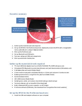
- 1. Executive summary On/Off switch A fully self-contained Bluetooth-to-ProChrono interface powered by three AA batteries Steady LED indicates Bluetooth connection Jack connects to ProChrono 1. Gather up the materials and tools required. 2. Set up the BT2S for the ProChrono baud rate. (Optionally rename the BT2S with a recognizable name, optionally set a unique 4-digit passcode.) 3. Wire-up the ProChrono jack. 4. Set up Bluetooth and COM ports. 5. Test your wiring and COM port assignments. 6. Wire-up and install in battery box. Gather up the materials & tools required TTL-level USB Serial adapter (such as a Prolific PL2303HX TTL/UART) (Amazon.com) Virtuabotix BT2S Bluetooth-to-serial slave (Amazon.com) and documentation (Virtuabotix.com) 4 AA Battery Box with switch (Radio Shack) 3.5mm male-to-male patch cord (Radio Shack) or a 3.5mm jack and some 3-conductor wire Rubber grommet that is a snug fit for the patch cord (Radio Shack) Zip tie (hardware store) 10K 1/8W resistor (Radio Shack) Soldering iron, solder, wire cutters, heat shrink tubing or electrical tape Terminal software such as AccessPort (free download) Built-in Bluetooth (BT) on your computer, or a BT dongle ProChrono software (PCRemote, free download from Competition Electronics website) Set up the BT2S for the ProChrono baud rate: 1. Install the USB serial adapter software on your computer.
- 2. 2. Connect the USB serial adapter to the BT2S using the connector pins on the adapter: Prolific PL2303HX TX RX RX TX GND 10K VCC (3.5-6V) BT2S 10K Note: I found it easiest to solder the 10K resistor directly to the pins on the BT2S board. Be careful soldering on the BT2S board. 3. Plug into your computer the USB serial adapter and use Device Manager to identify the COM port assigned to the adapter. (Start, Control Panel, Device Manager, Ports (COM & LPT), should say something like “Prolific USB-to-Serial COMM Port (COM?).) The red LED on the BT2S board should blink, indicating power is on but the Bluetooth connection has not been established. Note: You cannot proceed with the following steps if the Bluetooth connection is established with the BT2S. Read the BT2S documentation for more information. 4. Launch the terminal software, select the COM port for the adapter, and adjust the port settings as follows: Baud: 9600 Parity: NONE Data Bit: 8 Stop Bit: 1 Buffer Size: 8192 (don’t know if this is important) CHAR format for Send/Display (if shown) The rest of the settings should default to an acceptable value 5. Using ALL CAPS, type AT and click Send (or press Enter depending on your terminal program) and the BT2S should return OK. (AT means “attention”, and OK means the BT2S heard the command and understood it.) This confirms the BT2S is ready to receive programming commands. 6. Using ALL CAPS, type AT+BAUD1 and click Send. The BT2S should return OK, and the baud rate should now be set to 1200. 7. Go to the settings for your terminal program (as in step 4 above) and change the baud rate to 1200. Type AT and click Send, and the BT2S should return OK. This indicates the baud rate is now correctly set to 1200 and the BT2S is ready to receive more commands. 8. If you want to change the name of the device as it will appear in your Bluetooth menu, for example type this: AT+NAMEProChrono and click Send (it’s okay to use lower case for the BT name of the device). Now when you link BT to the BT2S it will appear as ProChrono. 9. If you want you can change the default pin code 1234 to any 4-digit code. I don’t recommend this, but if you want to do it read the documentation from Virtuabotix.
- 3. 10. Just to make sure all is well, type AT and click Send, the BT2S should return OK. 11. If you have trouble with any of this, I probably cannot help you as everything I know is contained in these steps. I’m not holding out. You can contact Virtuabotix support as I have found them to be very responsive and helpful. Wire-up the ProChrono jack 1. Unplug the USB serial adapter from the computer. 2. Disconnect the TX and RX wires at the USB serial adapter from the BT2S. Leave the GND and VCC wires connected (provides reliable power for the BT2S for testing purposes). 3. Wire-up the 3.5mm stereo jack to the BT2S (cut the patch cord in half). Be sure to connect the GND from the USB adapter to the shield on the jack. 3.5mm Stereo Jack Keep connected To PL2303HX TIP RING SHIELD TX RX RX TX BT2S 10K GND VCC (3.5-6V) Set up Bluetooth and COM ports 1. Enable Bluetooth if it’s internal to your computer. Otherwise, install the Bluetooth dongle. 2. Connect the USB adapter to your computer to supply power to the BT2S board. The red LED should blink indicating power to the board is on, but it is not linked via BT. 3. “Add a Bluetooth Device” on your computer, using whatever method is required for BT on your computer. The device should show as ProChrono if you set that name when setting up the baud rate. 4. Enter the pin 1234 when prompted. 5. The BT2S will momentarily connect via BT, and then immediately disconnect. You probably won’t even notice. 6. “Open Settings” for Bluetooth hardware on your computer. Methods vary depending on the Bluetooth hardware.
- 4. 7. If the COM ports for Bluetooth don’t look like this, you’ll need to make some adjustments in Device Manager: Note: I found through some painful trial and error, that with my setup, the Bluetooth COM Ports had to be set up as shown in this screen snapshot. If not, the ProChrono software would not recognize the com port. The virtual Bluetooth serial COM ports are automatically assigned by Windows, and if you get lucky they will be correct. If not, you’ll need to change the assigned ports using Device Manager. Note: With the above settings, when you launch the ProChrono software, you will select COM5 as the communication port. The other two ports are “phantom virtual ports” used by Windows to make the asynchronous full-duplex serial communications work with Bluetooth. 8. If you need to adjust the automatically-assigned COM ports to match the screen snapshot above, do this:
- 5. 2. Click Device Manager. 5. Click Advanced. 6. Click COM number and choose correct port. 3. Click Ports (COM & LPT). 4. Click the port to change. 1. Click Start, Control Panel. 7. Click OK to close all windows and save changes. NOTE: You may need to “move around” a previously-assigned COM port that you need to assign to one of the three Bluetooth serial ports: 9. When you’re finished re-assigning ports in Device Manager, repeat Step 7 and make sure the ports are assigned as shown. Test your wiring and COM port assignments 1. Install the ProChrono software on your computer. The software (at the time of this writing) is available as a free download from Competition Electronics. If you Google “competition electronics prochrono software” you should be able to find the page with the download. 2. Connect the 3.5mm jack to the chronograph, turn on the chronograph, and make sure the USB cable is plugged into your computer. The red LED should be blinking on BT2S indicating it has power but is not linked via BT. Remember the USB serial adapter needs to be plugged into your computer to provide power to the BT2S. 3. Launch the ProChrono software, select COM5, and the red LED should go steady indicating the BT communication link has been established. 4. Test the communication link by clicking String Change, the display should increment Current String by one and the ProChrono display should also increment by one. That’s it; the two-way communications have been established.
- 6. Wire-up the battery & finalize 1. Disconnect the USB serial adapter from the computer and the 3.5mm jack from the ProChrono. 2. Disconnect all of the wires from the BT2S board; they will all be re-soldered to the board. 3. Modify the battery box to accept the BT2S board and to provide 4.5 VDC from three AA batteries: Drill hole for grommet & wires Cut battery terminal here Cut battery terminal here Solder red wire to back side of terminal Switch is under here a. The idea here is to wire three AA batteries in series for a total of 4.5 VDC (1.5+1.5+1.5=4.5). To do this, you’ll need to move the red wire “back” one battery in the 4-battery compartment. This works great because the BT2S board will fit in the space where the 4th battery would be. b. Pull out the battery terminals at the end of the box that are farthest away from the switch. The red wire(+) should be soldered to one of these terminals. c. Cut the terminals in half, de-solder the red wire, and re-solder it to the terminal at the end opposite the switch. d. Reinsert the battery connectors. e. Drill a hole to accept the patch cord wire and grommet. f. (Optional) Drill a hole to allow the red LED on the BT2S to be seen while the battery box is closed. 4. Install the grommet on the box and slide the patch cord through. 5. Solder the wires directly to the back side of the BT2S board at the pins:
- 7. Be careful soldering wires to back side of board – do not cause shorts! Hole here allows red LED to be visible NOTE: Soldering wires to the back side of board and leaving the pin header soldered to the board allows the USB serial adapter to be connected later for troubleshooting or for changing parameters. a. Red (+) from the battery box to VCC. b. Black (-) from the battery box and shield from the patch cord to GND (one end of the 10K resistor is also soldered here). c. Ring (RX) from the 3.5mm jack to TX. d. Tip (TX) from the 3.5mm jack to RX (the other end of the 10K resistor is also soldered here). 6. Put a zip tie on the end of the patch cord to prevent it from being pulled against the solder connections. 7. Install 3 AA batteries and test the set up: Carefully install the BT2S board in the “unoccupied” slot of the battery compartment a. Plug the 3.5mm jack into the ProChrono.
- 8. b. Turn on the BT2S. c. Turn on the ProChono. d. Launch the ProChrono software and test the communications. Install some self-adhesive Velcro under here and under the ProChrono Notes If you are not completely comfortable with any of the steps in this document, DON’T DO IT! I am not responsible for your ability or lack thereof, and I will not be responsible for any damage you might cause while following, or attempting to follow, these instructions. I have told you everything I know about making this work. If I have made an error please let me know and I will fix it. If you’ve tried making it work and it doesn’t, you can post a query on the forum where you found this document and if possible, I will try to help, but I am giving this away freely and I do not warrant or guarantee any response. This document is freely made available. If you paid for this document, somebody has cheated you. This interface represents my intellectual property. You can make as many as you wish, but you may not sell them for a profit without my permission. If you find an error please let me know and I’ll fix it. If you find better ways to do any of these things, that’s great, feel free to post that advice on the forum where you found this document. As of this writing (May 2, 2013) the ProChrono software called PCRemote was made available for free by Competition Electronics on their web site. If for whatever reason that software is no longer available on their web site, don’t ask me for it because I won’t give it to you. That would violate copyright laws. I DO NOT provide help or support for the ProChrono software.