Structural Analysis and Design of Foundations: A Comprehensive Handbook for S...
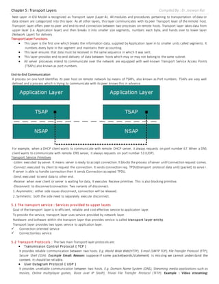
transport layer
1. Chapter 5 : Transport Layers Compiled By : Er. Jeewan Rai
Next Layer in OSI Model is recognized as Transport Layer (Layer-4). All modules and procedures pertaining to transportation of data or
data stream are categorized into this layer. As all other layers, this layer communicates with its peer Transport layer of the remote host.
Transport layer offers peer-to-peer and end-to-end connection between two processes on remote hosts. Transport layer takes data from
upper layer (i.e. Application layer) and then breaks it into smaller size segments, numbers each byte, and hands over to lower layer
(Network Layer) for delivery.
Transport Layer Functions
This Layer is the first one which breaks the information data, supplied by Application layer in to smaller units called segments. It
numbers every byte in the segment and maintains their accounting.
This layer ensures that data must be received in the same sequence in which it was sent.
This layer provides end-to-end delivery of data between hosts which may or may not belong to the same subnet.
All server processes intend to communicate over the network are equipped with well-known Transport Service Access Points
(TSAPs) also known as port numbers.
End-to-End Communication
A process on one host identifies its peer host on remote network by means of TSAPs, also known as Port numbers. TSAPs are very well
defined and a process which is trying to communicate with its peer knows this in advance.
For example, when a DHCP client wants to communicate with remote DHCP server, it always requests on port number 67.When a DNS
client wants to communicate with remote DNS server, it always requests on port number 53 (UDP).
Transport Service Primitives
-Listen: executed by server. It means server is ready to accept connection. It blocks the process of server until connection request comes.
-Connect: executed by client to request the connection. It sends connection req. TPDU(transport protocol data unit) (packet) to serve r.
If server is able to handle connection then it sends Connection accepted TPDU.
-Send: executed to send data to other end.
-Receive: when ever client or server is waiting for data, It executes Receive primitive. This is also blocking primitive.
-Disconnect: to disconnect connection. Two variants of disconnect.
1. Asymmetric: either side issues disconnect, connection will be released.
2. Symmetric: both the side need to separately execute disconnect.
5.1 The transport service : Services provided to upper layers
Goal of the transport layer is to efficient, reliable and cost effective service to application layer.
To provide the service, transport layer uses service provided by network layer.
Hardware and software within the transport layer that provides service is called transport layer entity.
Transport layer provides two types service to application layer.
Connection oriented service
Connectionless service
5.2 Transport Protocols : The two main Transport layer protocols are:
Transmission Control Protocol ( TCP )
It provides reliable communication between two hosts. E.g. World Wide Web(HTTP), E-mail (SMTP TCP), File Transfer Protocol (FTP),
Secure Shell (SSH). Example :Email: Reason: suppose if some packet(words/statement) is missing we cannot understand the
content. It should be reliable.
User Datagram Protocol ( UDP )
It provides unreliable communication between two hosts. E.g. Domain Name System (DNS), Streaming media applications such as
movies, Online multiplayer games, Voice over IP (VoIP), Trivial File Transfer Protocol (TFTP). Example : Video streaming:
2. Chapter 5 : Transport Layers Compiled By : Er. Jeewan Rai
Reason: Suppose if some packet(frame/sequence) is missingwecan understand the content. Becausevideo is collection of frames.
For 1 second video, there should be 25 frames(image). Even though we can understand some frames are missing due to our
imagination skills.
The transmission Control Protocol (TCP ) is one of the most important protocols of Internet Protocols suite. It is most widely used protocol
for data transmission in communication network such as internet.
Features
TCP is reliable protocol. That is, the receiver always sends either positive or negative acknowledgement about the data packet
to the sender, so that the sender always has bright clue about whether the data packet is reached the destination or it needs to
resend it.
TCP ensures that the data reaches intended destination in the same order it was sent.
TCP is connection oriented. TCP requires that connection between two remote points be established before sending actual data.
TCP provides error-checking and recovery mechanism.
TCP provides end-to-end communication.
TCP provides flow control and quality of service.
TCP operates in Client/Server point-to-point mode.
TCP provides full duplex server, i.e. it can perform roles of both receiver and sender.
Header
The length of TCP header is minimum 20 bytes long and maximum 60 bytes.
Source Port (16-bits) - It identifies source port of the application process on the sending device.
Destination Port (16-bits) - It identifies destination port of the application process on the receiving device.
Sequence Number (32-bits) - Sequence number of data bytes of a segment in a session.
Acknowledgement Number (32-bits) - When ACK flag is set, this number contains the next sequence number of the data byte
expected and works as acknowledgement of the previous data received.
Data Offset (4-bits) - This field implies both, the size of TCP header (32-bit words) and the offset of data in current packet in the
whole TCP segment.
Reserved (3-bits) - Reserved for future use and all are set zero by default.
Flags (1-bit each)
o NS - Nonce Sum bit is used by Explicit Congestion Notification signaling process.
o CWR - When a host receives packet with ECE bit set, it sets Congestion Windows Reduced to acknowledge that ECE
received.
o ECE -It has two meanings:
If SYN bit is clear to 0, then ECE means that the IP packet has its CE (congestion experience) bit set.
If SYN bit is set to 1, ECE means that the device is ECT capable.
o URG - It indicates that Urgent Pointer field has significant data and should be processed.
o ACK - It indicates that Acknowledgement field has significance. If ACK is cleared to 0, it indicates that packet does not
contain any acknowledgement.
o PSH - When set, it is a request to the receiving station to PUSH data (as soon as it comes) to the receiving application
without buffering it.
o RST - Reset flag has the following features:
It is used to refuse an incoming connection.
It is used to reject a segment.
It is used to restart a connection.
o SYN - This flag is used to set up a connection between hosts.
o FIN - This flag is used to release a connection and no more data is exchanged thereafter. Because packets with SYN and
FIN flags have sequence numbers, they are processed in correct order.
Windows Size - This field is used for flow control between two stations and indicates the amount of buffer (in bytes) the receiver
has allocated for a segment, i.e. how much data is the receiver expecting.
3. Chapter 5 : Transport Layers Compiled By : Er. Jeewan Rai
Checksum - This field contains the checksum of Header, Data and Pseudo Headers.
Urgent Pointer - It points to the urgent data byte if URG flag is set to 1.
Options - It facilitates additional options which are not covered by the regular header. Option field is always described in 32-bit
words. If this field contains data less than 32-bit, padding is used to cover the remaining bits to reach 32-bit boundary.
Addressing
TCP communication between two remote hosts is done by means of port numbers (TSAPs). Ports numbers can range from 0 – 65535
which are divided as:
System Ports (0 – 1023)
User Ports ( 1024 – 49151)
Private/Dynamic Ports (49152 – 65535)
Connection Management
TCP communication works in Server/Client model. The client initiates the connection and the server either accepts or rejects it. Three-
way handshaking is used for connection management.
Establishment
Client initiates the connection and sends the segment with aSequence number.
Server acknowledges it back with its own Sequence number and ACK of client’s
segment which is one more than client’s Sequence number. Client after
receiving ACK of its segment sends an acknowledgement of Server’s response.
Release
Either of server and client can send TCP segment with FIN flag set to 1. When
the receiving end responds it back by ACKnowledging FIN, that direction of TCP
communication is closed and connection is released.
Bandwidth Management
TCP uses the concept of window size to accommodate the need of Bandwidth
management. Window size tells the sender at the remote end, the number of
data byte segments the receiver at this end can receive. TCP uses slow start
phase by using window size 1 and increases the window size exponentially after
each successful communication.
For example, the client uses windows size 2 and sends 2 bytes of data. When
the acknowledgement of this segment received the windows size is doubled to
4 and next sent the segment sent will be 4 data bytes long. When the
acknowledgement of 4-byte data segment is received, the client sets windows size to 8 and so on.
If an acknowledgement is missed, i.e. data lost in transit network or it received NACK, then the window size is reduced to half and slow
start phase starts again.
Error Control &and Flow Control
TCP uses port numbers to know what application process it needs to handover the data segment. Along with that, it uses sequence
numbers to synchronize itself with the remote host. All data segments are sent and received with sequence numbers. The Sender knows
which last data segment was received by the Receiver when it gets ACK. The Receiver knows about the last segment sent by the Sender
by referring to the sequence number of recently received packet.
If the sequence number of a segment recently received does not match with the sequence number the receiver was expecting, then it is
discarded and NACK is sent back.If two segments arrive with the same sequence number, the TCP timestamp value is compared to make
a decision.
Multiplexing
The technique to combine two or more data streams in one session is called Multiplexing. When a TCP client initializes a connection with
Server, it always refers to a well-defined port number which indicates the application process. The client itself uses a randomly generated
port number from private port number pools.
Using TCP Multiplexing, a client can communicate with a number of different application process in asingle session. For example, a client
requests a web page which in turn contains different types of data (HTTP, SMTP, FTP etc.) the TCP session timeout is increased and the
session is kept open for longer time so that the three-way handshake overhead can be avoided.
This enables the client system to receive multiple connection over single virtual connection. These virtual connections are not good for
Servers if the timeout is too long.
Congestion Control
When large amount of data is fed to system which is not capable of handling it, congestion occurs. TCP controls congestion by means of
Window mechanism. TCP sets a window size telling the other end how much data segment to send. TCP may use three algorithms for
congestion control:
Additive increase, Multiplicative Decrease
Slow Start
Timeout React
Timer Management
TCP Connection
4. Chapter 5 : Transport Layers Compiled By : Er. Jeewan Rai
TCP uses different types of timer to control and management various tasks:
Keep-alive timer:
This timer is used to check the integrity and validity of a connection.
When keep-alive time expires, the host sends a probe to check if the connection still exists.
Retransmission timer:
This timer maintains stateful session of data sent.
If the acknowledgement of sent data does not receive within the Retransmission time, the data segment is sent again.
Persist timer:
TCP session can be paused by either host by sending Window Size 0.
To resume the session a host needs to send Window Size with some larger value.
If this segment never reaches the other end, both ends may wait for each other for infinite time.
When the Persist timer expires, the host re-sends its window size to let the other end know.
Persist Timer helps avoid deadlocks in communication.
Timed-Wait:
After releasing a connection, either of the hosts waits for a Timed-Wait time to terminate the connection completely.
This is in order to make sure that the other end has received the acknowledgement of its connection termination request.
Timed-out can be a maximum of 240 seconds (4 minutes).
Crash Recovery
TCP is very reliable protocol. It provides sequence number to each of byte sent in segment. It provides the feedback mechanism i.e. when
a host receives a packet, it is bound to ACK that packet having the next sequence number expected (if it is not the last segment).
When a TCP Server crashes mid-way communication and re-starts its process it sends TPDU broadcast to all its hosts. The hosts can then
send the last data segment which was never unacknowledged and carry onwards.
CONNECTION ORIENTED : Connection-Oriented means that when devices communicate, they perform handshaking to set up an end-to-end
connection. The handshaking process may be as simple as syncrhonization such as in the transport layer protocol TCP, or as complex as
negotiating communications parameters as with a modem.
Connection-Oriented systems can only work in bi-directional communications environments. To negotiate a connection, both sides must
be able to communicate with each other. This will not work in a unidirectional environment.
CONNECTIONLESS : Connectionless means that no effort is made to set up a dedicated end-to-end connection.
Connectionless communication is usually achieved by transmitting information in one direction, from source to destination without
checking to see if the destination is still there, or if it is prepared to receive the information. When there is little interferance, and plenty
of speed available, these systems work fine. In environments where there is difficulty transmitting to the destination, information may
have to be re-transmitted several times before the complete message is received.
Walkie-talkies, or Citizens Band radios are a good examples of connectionless communication. You speak into the mike, and the radio
transmitter sends out your signal. If the person receiving you doesn't understand you, there's nothing his radio can do to correct things,
the receiver must send you a message back to repeat your last message.
The User Datagram Protocol (UDP)
UDP is simplest Transport Layer communication protocol available of the TCP/IP protocol suite. It involves minimum amount of
communication mechanism. UDP is said to be an unreliable transport protocol but it uses IP services which provides best effort delivery
mechanism.
In UDP, the receiver does not generate an acknowledgement of packet received and in turn, the sender does not wait for any
acknowledgement of packet sent. This shortcoming makes this protocol unreliable as well as easier on processing.
Requirement of UDP
A question may arise, why do we need an unreliable protocol to transport the data? We deploy UDP where the acknowledgement packets
share significant amount of bandwidth along with the actual data. For example, in case of video streaming, thousands of packets are
forwarded towards its users. Acknowledging all the packets is troublesome and may contain huge amount of bandwidth wastage. The
best delivery mechanism of underlying IP protocol ensures best efforts to deliver its packets, but even if some packets in video streaming
get lost, the impact is not calamitous and can be ignored easily. Loss of few packets in video and voice traffic sometimes goes unnoticed.
Features
UDP is used when acknowledgement of data does not hold any significance.
UDP is good protocol for data flowing in one direction.
UDP is simple and suitable for query based communications.
UDP is not connection oriented.
UDP does not provide congestion control mechanism.
UDP does not guarantee ordered delivery of data.
UDP is stateless.
UDP is suitable protocol for streaming applications such as VoIP, multimedia streaming.
UDP Header
UDP header is as simple as its function.
5. Chapter 5 : Transport Layers Compiled By : Er. Jeewan Rai
UDP header contains four main parameters:
Source Port - This 16 bits information is used to identify the source port of the packet.
Destination Port - This 16 bits information, is used identify application level service on destination machine.
Length - Length field specifies the entire length of UDP packet (includingheader). It is 16-bits field and minimum value is 8-byte,
i.e. the size of UDP header itself.
Checksum - This field stores the checksum value generated by the sender before sending. IPv4 has this field as optional so when
checksum field does not contain any value it is made 0 and all its bits are set to zero.
UDP application
Here are few applications where UDP is used to transmit data:
Domain Name Services
Simple Network Management Protocol
Trivial File Transfer Protocol
Routing Information Protocol
Kerberos
5.3 Port and Socket
PORT
• One of the circuit connection points on a front end processor or local
intelligent controller
• The TCP and UDP protocols use ports to map incoming data to a particular
process running on a computer
• At the transport layer, an address is needed to choose among multiple
processes running on the destination host called Port Number
Destination Port Number for delivery
Source Port Number for reply
• Port is represented by a positive (16-bit ) integer value between 0 and
65,535
• Some ports have been reserved to support common / well known services
ftp 21/tcp
telnet 23/tcp
smtp 25/tcp
login 513/tcp
• User level process/services generally use port number value >= 1024
SOCKET
• A Socket is one endpoint of a two-way communication link between two
processes running on the network
• A socket is bound to a port number so that the TCP layer can identify the
application that data is destined to be sent
• TCP connection can be uniquely identified by its two endpoints, multiple
connections are possible between host and the server
• Sockets provide an interface for programming networks at the transport
layer
• Process to Process delivery of data needs two identifiers, IP Address and Port Number at each endpoint
• Socket Address combination of IP address and a Port number
• Transport Layer Protocol needs a pair of Socket addresses
• Client Socket Address
• Uniquely defines the Client Process
• Server Socket Address
• Uniquely defines Server Process
• Both Socket Addresses contain IP Header and Transport Layer Protocol Header
• IP Header contains IP Addresses
• TCP & UDP Header contains the Port Numbers
Types of Socket
• Active Socket
Port
Fig.Port
Fig.SocketExample
Dest.
Host
P
o
r
t
SRC
Host
TCP
TCP or UDP
Port Port Port Port
Process 1 Process 2 Process 3 Process 4
Port# Data
Data
Packet
200.23.56.8 69
200.23.56.8 69
<-- Port NumberI P Address
Socket Address
6. Chapter 5 : Transport Layers Compiled By : Er. Jeewan Rai
o Connected to a remote active socket via an open data connection
o Closing the connection, destroys the active sockets at each point
• Passive Socket
o Connected, but awaits an incoming connection, which will spawn a new active socket
5.4 Connection Establishment and Connection Release
Scenarios for establishing a connection using a three-way handshake. CR denotes CONNECTION REQUEST.
(a) Normal operation,
(b) Old CONNECTION REQUEST appearing out of nowhere.
Connection Release
Connection at transport can be released in two way.
1.asymmetric: if one of host terminates connection,then
in both the direction, data communication will be
terminated.
2. symmetric: if one of the host disconnects connection,
then it cannot send the data but it can receive it.
- host A opens the connection with an ISN
- host B accepts the connect request by sending a TCP
segment which
o acknowledges host A's request (ACK flag on)
o sets acknowledgement number to ISN+1
o makes its own connection request (SYN flag on) with an ISN
- host A acknowledges this request
- note that the SYN flag "consumes" one byte of sequence space so that it can be acknowledged unambiguously
7. Chapter 5 : Transport Layers Compiled By : Er. Jeewan Rai
Asymmetric Release
Abrupt disconnection with loss of data.
(a) Normal case of a three-way handshake. (b) final ACK lost.
(c) Response DR lost (d) Response lost and subsequent DRs lost.
TCP Connection Release uses symmetric approach. It is called Four Way handshaking for connection termination.
a three-way handshake is also used to terminate a connection
in this example, host 1 terminates the connection by transmitting a segment with the FIN flag set containing optional data
host 2 acknowledges this (the FIN flag also consumes one byte of sequence space) and sets its own FIN flag
the third and last segment contains host 1's acknowledgement of host 2's FIN flag
8. Chapter 5 : Transport Layers Compiled By : Er. Jeewan Rai
5.5 Flow Control and Buffering
Transport layer manages end to end to flow. If the receiver is not able to copewith the flow of data, then data flow should be control
from sender side, that part is done on Transport layer.
Data link layer is also doing flow control, but it controls flow of data between adjacent nodes in path from source to destination.
Reasons of packet loss at receiver is slow processing speed or insufficient buffer to store the data.
Buffer are allocated at sender and receiver side. If the network service is reliable, so every send TPDU sent will be delivered to receiver
and will be buffered and processes at receiver, so no need to keep buffer at sender.
But if network service is unreliable and receiver may not able to handle every incoming TPDU then sender should also keep a buffer,
where copy of TPDU resides until it’s ACK comes.
Buffers can be allocate in fixed size when connection sets up or buffer can be varied dynamically according to free memory. First
case is called static buffer allocation.
(a) Chained fixed-size buffers. (b) Chained variable-sized buffers. (c) One large circular buffer per connection.
Dynamic Buffer Allocation: as connection are opened and closed,
memory available changes, so sender and receiver dynamically
adjust buffer allocations.
In dynamic buffer allocation, initially sender will request certain
number of buffers based on perceive need. receiver will grant as
many buffers as it can.
5.6 Multiplexing and Demultiplexing
a socket is the interface through which a process (application)
communicates with the transport layer
each process can potentially use many sockets
the transport layer in a receiving machine receives a sequence of
segments from its network layer
delivering segments to the correct socket is called demultiplexing
assembling segments with the necessary information and passing them to the network layer is called multiplexing
multiplexing and demultiplexing are need whenever a communications channel is shared
Sender Receiver
<Req. 8 buffers>
<Buff Alloc. 4>
<Seq.:0, data=m0>
< Seq.:1, data=m1>
< Seq.:2, data=m2 >
<Ack:2, Buf:2>
<Seq.:3, data=m3>
<Seq.:4, data=m4>
9. Chapter 5 : Transport Layers Compiled By : Er. Jeewan Rai
Connectionless Multiplexing and Demultiplexing
say a process on Host A, with port number 19157,wants to send data to a process with UDP port 46428 on Host B
transport layer in Host A creates a segment containing source port, destination port, and data
passes it to the network layer in Host A
transport layer in Host B examines destination port number and delivers segment to socket identified by port 46428
note: a UDP socket is fully identified by a two-tuple consisting of
o a destination IP address
o a destination port number
source port number from Host A is used at Host B as "return address":
Connection-Oriented Multiplexing and Demultiplexing
each TCP connection has exactly two end-points
this means that two arriving TCP segments with different source IP addresses or source port numbers will be directed to
two different sockets, even if they havethe same destination port number
so a TCP socket is identified by a four-tuple:
(source IP address, source port #, destination IP address, destination port #)
10. Chapter 5 : Transport Layers Compiled By : Er. Jeewan Rai
recall UDP uses only (destination IP address, destination port #)
Multiplexing and Demultiplexing Example
an example where clients A and C both communicate with B on port 80:
5.7 Congestion Control Algorithm : Token Bucket and Leaky Bucket Transport Layer
Congestion is an important issue that can arise in packet switched network. Congestion is a situation in Communication Networks in which
too many packets are present in a part of the subnet, performance degrades. Congestion in a network may occur when the load on the
network (i.e. the number of packets sent to the network) is greater than the capacity of the network (i.e. the number of packets anetwork
can handle.)
Causing of Congestion:
The various causes of congestion in a subnet are:
1.The input traffic rate exceeds the capacity of the output lines. If suddenly, a stream of packet start arriving on three or four input lines
and all need the same output line. In this case, a queue will be built up. If there is insufficient memory to hold all the packets, the packet
will be lost. Increasing the memory to unlimited size does not solve the problem. This is because, by the time packets reach front of the
queue, they have already timed out (as they waited the queue). When timer goes off source transmits duplicate packet that are also added
to the queue. Thus same packets are added again and again, increasing the load all the way to the
destination.
2.The routers are too slow to perform bookkeeping tasks (queuing buffers, updating tables, etc.).
3.The routers' buffer is too limited.
11. Chapter 5 : Transport Layers Compiled By : Er. Jeewan Rai
4.Congestion in a subnet can occur if the processors are slow. Slow speed CPU at routers will perform the routine tasks such as queuing
buffers, updating table etc slowly. As a result of this, queues are built up even though there is excess line capacity.
5.Congestion is also caused by slow links. This problem will be solved when high speed links are used. But it is not always the case.
Sometimes increase in link bandwidth can further deteriorate the congestion problem as higher speed links may make the network more
unbalanced.Congestion can make itself worse. If a route!" does not have free buffers, it start ignoring/discarding the newly arriving
packets. When these packets are discarded, the sender may retransmit them after the timer goes off. Such packets are transmitted by the
sender again and again until the source gets the acknowledgement of these packets. Therefore multiple transmissions of packets will force
the congestion to take place at the sending end.
How to correct the Congestion Problem:
Congestion Control refers to techniques and mechanisms that can either prevent congestion, before it happens, or remove congestion,
after it has happened. Congestion control mechanisms are divided into two categories, one category prevents the congestion from
happening and the other category removes congestion after it has taken place.
These two categories are:
1. Open loop
2. Closed loop
Open Loop Congestion Control
• In this method, policies are used to prevent the congestion before it happens.
• Congestion control is handled either by the source or by the destination.
• The various methods used for open loop congestion control are:
1. Retransmission Policy
• The sender retransmits a packet, if it feels that the packet it has sent is lost or corrupted.
• However retransmission in general may increase the congestion in the network. But we need to implement good retransmission policy
to prevent congestion.
• The retransmission policy and the retransmission timers need to be designed to optimize efficiency and at the same time prevent the
congestion.
2. Window Policy
• To implement window policy, selective reject window method is used for congestion control.
• Selective Reject method is preferred over Go-back-n window as in Go-back-n method, when timer for a packet times out, several packets
are resent, although some may have arrived safely at the receiver. Thus, this duplication may make congestion worse.
• Selective reject method sends only the specific lost or damaged packets.
3. Acknowledgement Policy
• The acknowledgement policy imposed by the receiver may also affect congestion.
• If the receiver does not acknowledge every packet it receives it may slow down the sender and help prevent congestion.
• Acknowledgments also add to the traffic load on the network. Thus, by sending fewer acknowledgements we can reduce load on the
network.
• To implement it, several approaches can be used:
1. A receiver may send an acknowledgement only if it has a packet to be sent.
2. A receiver may send an acknowledgement when a timer expires.
3. A receiver may also decide to acknowledge only N packets at a time.
12. Chapter 5 : Transport Layers Compiled By : Er. Jeewan Rai
4. Discarding Policy
• A router may discard less sensitive packets when congestion is likely to happen.
• Such a discarding policy may prevent congestion and at the same time may not harm the integrity of the transmission.
5. Admission Policy
• An admission policy, which is a quality-of-service mechanism, can also prevent congestion in virtual circuit networks.
• Switches in a flow first check the resource requirement of a flow before admitting it to the network.
• A router can deny establishing a virtual circuit connection if there is congestion in the "network or if there is a possibility of future
congestion.
Closed Loop Congestion Control
• Closed loop congestion control mechanisms try to remove the congestion after it happens.
• The various methods used for closed loop congestion control are:
1. Backpressure
• Backpressure is a node-to-node congestion control that starts with a node and propagates, in the opposite direction of data flow.
• The backpressure technique can be applied only to virtual circuit networks. In such virtual circuit each node knows the upstream node
from which a data flow is coming.
• In this method of congestion control, the congested node stops receiving data from the immediate upstream node or nodes.
• This may cause the upstream node on nodes to become congested, and they, in turn, reject data from their upstream node or nodes.
• As shown in fig node 3 is congested and it stops receiving packets and informs its upstream node 2 to slow down. Node 2 in turns may
be congested and informs node 1 to slow down. Now node 1 may create congestion and informs the source node to slow down. In this
way the congestion is alleviated. Thus, the pressure on node 3 is moved backward to the source to remove the congestion.
2. Choke Packet
• In this method of congestion control, congested router or node sends a special type of packet called choke packet to the source to
inform it about the congestion.
• Here, congested node does not inform its upstream node about the congestion as in backpressure method.
• In choke packet method, congested node sends a warning directly to the source station i.e. the intermediate nodes through which the
packet has traveled are not warned.
3. Implicit Signaling
• In implicit signaling, there is no communication between the congested node or nodes and the source.
• The source guesses that there is congestion somewhere in the network when it does not receive any acknowledgment. Therefore the
delay in receiving an acknowledgment is interpreted as congestion in the network.
• On sensing this congestion, the source slows down.
• This type of congestion control policy is used by TCP.
4. Explicit Signaling
• In this method, the congested nodes explicitly send a signal to the source or destination to inform about the congestion.
• Explicit signaling is different from the chokepacket method. In chokepacked method, a separate packet is used for this purpose whereas
in explicit signaling method, the signal is included in the packets that carry data .
• Explicit signaling can occur in either the forward direction or the backward direction .
13. Chapter 5 : Transport Layers Compiled By : Er. Jeewan Rai
• In backward signaling, a bit is set in a packet moving in the direction opposite to the congestion. This bit warns the source about the
congestion and informs the source to slow down.
• In forward signaling, a bit is set in a packet moving in the direction of congestion. This bit warns the destination about the congestion.
The receiver in this case uses policies such as slowing down the acknowledgements to remove the congestion.
packet loss typically results from buffer overflow in routers as the network becomes congested
congestion results from too many senders trying to send data at too high a rate
packet retransmission treats a symptom of congestion, but not the cause
to treat the cause, senders must be "throttled" (reduce their rate)
TCP implements a congestion control algorithm based on perceived congestion by the sender:
o if it perceives little congestion, it increases its send rate
o if it perceives there is congestion, it reduces its send rate
we will not cover the details of how TCP does this
The Leaky Bucket Algorithm used to control rate in a network.
It is implemented as a single-server queue with constant service -me.
If the bucket (buffer) overflows then packets are discarded.
The leaky bucket enforces a constant output rate (average rate) regardless of the burs-ness of the input. Does nothing when input
is idle.
The host injects one packet per clock -ck onto the network. This results in a uniform flow of packets, smoothing out bursts and
reducing conges-on.
When packets have the same size (as in ATM cells), one packet per -ck is okay. For variable length packets though, it is be[er to
allow a fixed number of bytes per -ck.E.g. 1024 bytes per -ck will allow one 1024-bytepacket or two 512-byte packets or four 256-
byte packets on 1 -ck.
Token Bucket (TB) Algorithm
The leaky bucket algorithm allows only an average (constant) rate of data flow. Its major problem is that it cannotdeal with bursty
data.
A leaky bucket algorithm does not consider the idle time of the host. For example, if the host was idle for 10 seconds and now it
is willing to send data at a very high speed for another 10 seconds, the total data transmission will be divided into 20 seconds
and average data rate will be maintained. The host is having no advantage of sitting idle for 10 seconds.
To overcome this problem, a token bucket algorithm is used. A token bucket algorithm allows bursty data transfers.
14. Chapter 5 : Transport Layers Compiled By : Er. Jeewan Rai
A token bucket algorithm is a modification of leaky bucket in which leaky bucket contains tokens.
In this algorithm, a token(s) are generated at every clock tick. For a packet to be transmitted, system must remove token(s) from
the bucket.
Thus, a token bucket algorithm allows idle hosts to accumulate credit for the future in form of tokens.
For example, if a system generates 100 tokens in one clock tick and the host is idle for 100 ticks. The bucket will contain 1 0,000
tokens.
Now, if the host wants to send bursty data, it can consume all 10,000 tokens at once for sending 10,000 cells or bytes.
Thus a host can send bursty data as long as bucket is not empty.
Difference between TCP and UDP
1) Connection oriented vs Connection less
First and foremost, difference between them is TCP is a connection oriented
protocol, and UDP is connection less protocol. This means a connection is
established between client and server, before they can send data. Connection
establishment process is also known as TCP hand shaking where control
messages are interchanged between client and server. Attached image
describe the process of TCP handshake, for example which control messages
are exchanged between client and server. Client, which is initiator of TCP
connection, sends SYN message to server, which is listening on a TCP port.
Server receives and sends a SYN-ACK message, which is received by client
again and responded using ACK. Once server receive this ACK message, TCP
connection is established and ready for data transmission. On the other hand,
UDP is a connection less protocol, and point to point connection is not
established before sending messages. That's the reason, UDP is more suitable
for multicast distribution of message, one to many distribution of data in
single transmission.
2) Reliability
TCP provides delivery guarantee, which means a message sent using TCP protocol is guaranteed to be delivered to client. If message is
lost in transits then its recovered using resending, which is handled by TCP protocol itself. On the other hand, UDP is unreliable, it
doesn't provide any delivery guarantee. A datagram package may be lost in transits. That's why UDP is not suitable for programs which
requires guaranteed delivery.
3) Ordering
Apart from delivery guarantee, TCP also guarantees order of message. Message will be delivered to client in the same order, server has
sent, though its possible they may reach out of order to the other end of the network. TCP protocol will do all sequencing and ordering
for you. UDP doesn't provide any ordering or sequencing guarantee. Datagram packets may arrive in any order. That's why TCP is
suitable for application which need delivery in sequenced manner, though there are UDP based protocol as well which provides ordering
Connection oriented
15. Chapter 5 : Transport Layers Compiled By : Er. Jeewan Rai
and reliability by using sequence number and redelivery e.g. TIBCO
Rendezvous, which is actually a UDP based application.
4) Data Boundary
TCP does not preserve data boundary, UDP does. In Transmission control
protocol, data is sent as a byte stream, and no distinguishing indications are
transmitted to signal message (segment) boundaries. On UDP, Packets are
sent individually and are checked for integrity only if they arrived. Packets
have definite boundaries which are honored upon receipt, meaning a read
operation at the receiver socket will yield an entire message as it was
originally sent. Though TCP will also deliver complete message after
assembling all bytes. Messages are stored on TCP buffers before sending to
make optimum use of network bandwidth.
5) Speed
In one word, TCP is slow and UDP is fast. Since TCP does has to create
connection, ensure guaranteed and ordered delivery, it does lot more than
UDP. This cost TCP in terms of speed, that's why UDP is more suitable
where speed is a concern, for example online video streaming, telecast or
online multi-player games.
6) Heavy weight vs Light weight
Because of the overhead mentioned above, Transmission control protocol
is considered as heavy weight as compared to light weight UDP protocol.
Simple mantra of UDP to deliver message without bearing any overhead of
creating connection and guaranteeing delivery or order guarantee keeps it
light weight. This is also reflected in their header sizes, which is used to
carry meta data.
7) Header size
TCP has bigger header than UDP. Usual header size of a TCP packet is 20
bytes which is more than double of 8 bytes, header size of UDP datagram
packet. TCP header contains Sequence Number, Ack number, Data offset, Reserved, Control bit, Window, Urgent Pointer, Options,
Padding, Check Sum, Source port, and Destination port. While UDP header only contains Length, Source port, Destination port, and
Check Sum.
8) Congestion or Flow control
TCP does Flow Control. TCP requires three packets to set up a socket connection, before any user data can be sent. TCP handles
reliability and congestion control. On the other hand, UDP does not have an option for flow control.
9) Usage and application
Where does TCP and UDP are used in internet? After knowing key differences between TCP and UDP, we can easily conclude, which
situation suits them. Since TCP provides delivery and sequencing guaranty, it is best suited for applications that require high reliability,
and transmission time is relatively less critical. While UDP is more suitable for applications that need fast, efficient transmission, such as
games. UDP's stateless nature is also useful for servers that answer small queries from huge numbers of clients. In practice, TCP is used
in finance domain e.g. FIX protocol is a TCP based protocol, UDP is used heavily in gaming and entertainment sites
10) TCP and UDP based Protocols
One of the best example of TCP based higher end protocol is HTTP and HTTPS, which is every where on internet. In fact most of the
common protocol you are familiar of e.g. Telnet, FTP and SMTP all are based over Transmission Control Protocol. UDP don't have any
thing as popular as HTTP but UDP is used in protocol like DHCP (Dynamic Host Configuration Protocol) and DNS (Domain Name System).
Some of the other protocol, which is based over User Datagram protocol is Simple Network Management Protocol
(SNMP), TFTP, BOOTP and NFS (early versions).
TCP Header Format
UDP Header Format