Zte cabinets
•Als PPTX, PDF herunterladen•
9 gefällt mir•7,930 views

The document provides information about ZTE cabinet hardware structures for various products, including: - The BTSV2.0 cabinet which uses CMM, TRM, BTM, and other modules. - The BS30(V1.2) cabinet which includes TSM, DPM, CMM, and other modules. - The M8206 cabinet hardware including antennas, LMT, RTU interface board, and other components. - Descriptions of the functions of key modules like CMM, TRM, and others.

Empfohlen
Weitere ähnliche Inhalte
Was ist angesagt?
Was ist angesagt? (20)
Andere mochten auch
Andere mochten auch (20)
Ähnlich wie Zte cabinets
Ähnlich wie Zte cabinets (20)
Zte cabinets
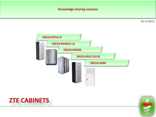
- 1. Knowledge sharing sessions 28/12/2010 ZXG10-BTSV2.0 ZXG10-BS30(V1.2) ZXG10-M8206 ZXG10-BS21 (V2.0) ZXG10-OB06 ZTE CABINETS
- 2. ZTE CABINETS 28/12/2010 1161 69 43 31 27 BTS V 2.0 BS21(V2.0) OB06 M8206 BS30(V1.2) ZTE Network ZTE CABINETS
- 3. WORKING PRINCIPLE 28/12/2010 Data Modelated base band signal Controller & Maintenance Antenna feeder processor link Base Band Processor Demodelated RF signal B Abis RF signal Um Module RF Unit interface S Control signal System C clock System clock Power Supply Module 220V Heat exchanger ZTE CABINETS
- 4. WORKING PRINCIPLE 28/12/2010 Data Modelated base band signal Controller & Maintenance Antenna feeder processor link Base Band Processor Demodelated RF signal B Abis RF signal Um Module RF Unit interface S Control signal System C clock System clock Downlink: The BTS receives data from BSC, including voice and signaling data. Power Supply Module The transmission unit sends signaling data to the operation & maintenance unit for processing. 220V The voice data are then sent to baseband processor for processing of rate conversion, encryption and interleaving. Heat exchanger Data are then sent to RF unit for modulation to high-frequency signals. Finally, data are then transmitted through the antenna feeder processor. ZTE CABINETS
- 5. WORKING PRINCIPLE 28/12/2010 Data Modelated base band signal Controller & Maintenance Antenna feeder processor link Base Band Processor Demodelated RF signal B Abis RF signal Um Module RF Unit interface S Control signal System C clock System clock Uplink: The antenna feeder processor receives the RF signals from the MS. It then Module signals to Power Supply sends these the RF unit to 220V into digital signals. convert The signals are then transmitted to baseband processor for rate signals conversion, decryption and de-interleaving. Heat exchanger After conversion to the code pattern, suitable for long-distance transmission, the signals are sent to the BSC through the Abis interface. ZTE CABINETS
- 6. Knowledge sharing sessions 28/12/2010 ZXG10-BTSV2.0 ZXG10-BS30(V1.2) ZXG10-M8206 ZXG10-BS21 (V2.0) ZXG10-OB06 ZTE CABINETS
- 7. Hardware Structure BTSV2.0 28/12/2010 MMI TR/ETRM1 Abis A Um BSC CMM TR/ETRM2 E M PDM TR/ETRM3 FCM BTM External communication bus ZTE CABINETS
- 8. Hardware Structure BTSV2.0 28/12/2010 MMI The CMM TR/ETRM1& Maintenance (Control Module) performs the following functions: Abis interface processing A Abis BTS operation & maintenance Um BSC CMM TR/ETRM2 Clock synchronization and generation E M Collection of internal/external alarms Fan management and the PDM TR/ETRM3 active/standby function FCM BTM External communication bus ZTE CABINETS
- 9. Hardware Structure BTSV2.0 28/12/2010 MMI The TRM/ETRM ( Transceiver Module ) TR/ETRM1 performs the following functions: Runs and Controls radio channels in A Abis system GSM Um BSC CMM Sends/receives radio channel data TR/ETRM2 E Modulates/demodulates baseband M signals on the radio carrier frequency PDM Sends/receives radio carrier signals and TR/ETRM3 collects alarms of the fans and AEMs. FCM BTM External communication bus ZTE CABINETS
- 10. Hardware Structure BTSV2.0 28/12/2010 MMI TR/ETRM1 Abis A Um BSC CMM TR/ETRM2 E M PDM TR/ETRM3 FCM The BTM (Backplane Transmission Module) contains Motherboard of CMM (MCMM), Motherboard of Transceiver BTM Module (MTRM). External communication bus ZTE CABINETS
- 11. Hardware Structure BTSV2.0 28/12/2010 MMI TR/ETRM1 AEM (Antenna Equipment Module) provides Abis the following functions: A Um Combines the transmit signals of multiple BSC CMM carriers. TR/ETRM2 E Provides bidirectional signal channels from M the BTS to the antenna for the transmitting PDM band and from the antenna to the BTS for TR/ETRM3 the receiving band. Gives an alarm when the VSWR of the FCM antenna portthe interference out of the Suppresses deteriorates. working band and spurious emission. Flexibly configures carriers. BTM Implements diversity receiving. External communication bus ZTE CABINETS
- 12. Hardware Structure BTSV2.0 28/12/2010 MMI TR/ETRM1 Abis A Um BSC CMM TR/ETRM2 E M PDM The PDM (Power Distribution Module) TR/ETRM3 performs the following functions: Distributes -48 V DC power to all the modules FCM Provides overload protection Stabilizes the input power BTM External communication bus ZTE CABINETS
- 13. Hardware Structure BTSV2.0 28/12/2010 MMI TR/ETRM1 Abis The FCM (Fan Control Module) monitors and A Um BSC CMM TR/ETRM2 collects the temperature in the carrier shelves E and dissipates heat through fans. M PDM TR/ETRM3 FCM BTM External communication bus ZTE CABINETS
- 14. Knowledge sharing sessions 28/12/2010 ZXG10-BTSV2.0 ZXG10-BS30(V1.2) ZXG10-M8206 ZXG10-BS21 (V2.0) ZXG10-OB06 ZTE CABINETS
- 15. Hardware Structure BS30(V1.2) 28/12/2010 TSM DPM HW signal TRM LNA Optical interface Backplane STM Receiving RX E1 CMM filter Dup TX Internal FAN PWM HTM AC 220V ZTE CABINETS
- 16. Hardware Structure BS30(V1.2) 28/12/2010 TSM DPM HW signal TRM LNA Optical interface Backplane STM Receiving RX E1 CMM filter Dup TX The transceiver for station module (TSM), consist of controller & maintenance module (CMM), transceiver module (TRM) and backboard connection unit (BCU) Internal FAN PWM HTM AC 220V ZTE CABINETS
- 17. Hardware Structure BS30(V1.2) 28/12/2010 TSM DPM HW signal TRM LNA Optical interface Backplane STM Receiving RX E1 CMM filter Dup TX The DPM (Duplexer Module ) provides bi- directional channels for signals between the BTS and the antenna, suppresses the interference and spurious radiation beyond Internal the working band, and implements SWR FAN PWM HTM alarm detection at the antenna port. AC 220V ZTE CABINETS
- 18. Hardware Structure BS30(V1.2) 28/12/2010 TSM DPM HW signal TRM LNA Optical interface Backplane STM Receiving RX E1 CMM filter CMM (Controller & Maintenance Module ) Dup provides such functions as Abis interface processing, BS operation & maintenance, clock synchronization and TX generation, and internal/external alarm collection and processing. CMM consists of a control O&M board. Internal FAN PWM HTM AC 220V ZTE CABINETS
- 19. Hardware Structure BS30(V1.2) 28/12/2010 TSM DPM HW signal TRM LNA Optical interface Backplane STM Receiving RX E1 CMM filter The ZXG10 BS30 supports built-in SDH Dup transmission equipment, which is implemented by configuring STM. The STM is the T150 researched and TX manufactured by ZTE. T150 provides the ZXG10 BS30 with 155 Mbits/s SDH interface, providing diversified BS transmission interfaces. Internal FAN PWM HTM AC 220V ZTE CABINETS
- 20. Hardware Structure BS30(V1.2) 28/12/2010 TSM DPM HW signal TRM LNA Optical interface Backplane STM PWM (Power Supply Module ) provides Receiving RX rectification, filtering and voltage E1 filter CMM stabilizing protection of 220 VAC (single- Dup phase three-lines), supplies 220 VAC for HTM, TSM, STM and internal/external fans, and provides 220 VAC input over/under-voltage dry contact alarm. TX Internal FAN PWM HTM AC 220V ZTE CABINETS
- 21. Hardware Structure BS30(V1.2) 28/12/2010 TSM DPM HW signal TRM LNA Optical interface Backplane STM Receiving RX E1 CMM filter Dup TX HTM (Heater Module) consists of a heater and a fan. It serves to control internal temperature and ensure the normal operation of the equipment. Internal FAN PWM HTM AC 220V ZTE CABINETS
- 22. Knowledge sharing sessions 28/12/2010 ZXG10-BTSV2.0 ZXG10-BS30(V1.2) ZXG10-M8206 ZXG10-BS21 (V2.0) ZXG10-OB06 ZTE CABINETS
- 23. Hardware Structure M8206 ANT ANT 28/12/2010 Delay ALM SYS CLK / 13M CLK LMT 3E1/T1 Abis ODU 48V 48V ZTE CABINETS
- 24. Hardware Structure M8206/RTU 28/12/2010 MDUP MDUP MPAU RTU Interface Board M P MTRB W R 48V ZTE CABINETS
- 25. Hardware Structure M8206/RTU 28/12/2010 MTRB (Micro Base Station Transceiver MDUP Board) MDUP consists of transmitter, receiver, local oscillator and base band processor. Main functions of MTRB are as follows: Transmission and reception of radio signal and uplink/downlink conversion. MPAU Processing the dual-carriers radio channels in downlink. Implement rate adaptation, channel encoding, interleaving, and encryption. Also generates TDMA burst pulse and implements GMSK/8PSK modulation. M Receives the system clock fromP CMB. R Implements and saves hardware management I MTRB W ID. B type, and Board version. R Implements RF hopping. 48V ZTE CABINETS
- 26. Hardware Structure M8206/RTU 28/12/2010 MDUP MDUP MPAU (Micro Base Station Power Amplifier Unit) is power amplifying unit and amplifies the downlink signal power. MPAU consists of two MPAU power amplifier boards which are installed on the bottom of base station cabinet respectively. M R P I MTRB W B R 48V ZTE CABINETS
- 27. Hardware Structure M8206/RTU 28/12/2010 MDUP MDUP MPAU This unit works as a duplexer and consists of transceiver duplexer, antenna interface VSWR detection unit and Low Noise Amplifier RTU Interface Board M (LNA). It detects VSWR alarms in three levels P MTRB W R 48V ZTE CABINETS
- 28. Hardware Structure M8206/RTU 28/12/2010 MDUP MDUP MPAU MPWR performs power distribution function. It provides RTU Interface Board different values of voltage M according to the requirements in P different parts of the RTU. MTRB W R 48V ZTE CABINETS
- 29. Hardware Structure M8206/CTU 28/12/2010 CIB PWR MCMB 5E1/T1 Test MMI 48V Heater MEIB 5E1/T1 T150 48V IDU ZTE CABINETS
- 30. Hardware Structure M8206/CTU 28/12/2010 CMB (control and maintenance board) stands for . Monitors, controls and maintains the whole BTS system. Provides 8 channels E1/T1 interfaces, but only 5 CIB channels are used in this system. PWR Implements the synchronization of radio clock and transmission clock. MCMB Provides transparent path for external environment alarm. 5E1/T1 Test MMI Implements shared PCM link for multi-BTS. 48V Supports cascaded capacity expansion of many Heater MEIB physical cabinets in one site. Provides various clocks required in BTS 5E1/T1 Administers the intra-system program of each board and version of FPGA configuration file. Supports near T150 end and far end version upgrade. 48V IDU Provides protection from reverse current. Its front panel provides reset button and forced power OFF button. ZTE CABINETS
- 31. Hardware Structure M8206/CTU 28/12/2010 CIB PWR CIFB (CTU Interface Board) implements the signal conversion MCMB between CMB and the bottom interface. 5E1/T1 Test MMI 48V Heater MEIB 5E1/T1 T150 48V IDU ZTE CABINETS
- 32. Hardware Structure M8206/CTU 28/12/2010 MEIB (Micro Base Station E1 Interface Board) performs the following functions: Provides circuit impedance matching for CIB five E1/T1 channels. PWR Maximum three E1/T1 channels can be MCMB used to connect embedded transmission equipment (optical or microwave transmission). Maximum three can be 5E1/T1 Test MMI used for cascading. 48V Heater Provides link bypass function for E1/T1 MEIB channels during the power down of cascading system (i.e. channel ‘A’ bypass 5E1/T1 to channel ‘C’). Provides lightening protection, and T150 48V signal isolation in the circuits. IDU It provides Abis interface board type information to CMB. ZTE CABINETS
- 33. Hardware Structure M8206/CTU 28/12/2010 CIB T150 is a PWR capacity AU-4 path STM-1 small level SDH equipment. It is usually used MCMB outdoors and is the auxiliary transmission equipment of GSM and CDMA BTSs. The function and interfaces are optimized5E1/T1 Test MMI according to the48V actual requirement of Heater GSM and CDMA. It provides STM-1 MEIB (155520 Kbps) link, which is equal to the capacity of four E1 links. 5E1/T1 T150 48V IDU ZTE CABINETS
- 34. Knowledge sharing sessions 28/12/2010 ZXG10-BTSV2.0 ZXG10-BS30(V1.2) ZXG10-M8206 ZXG10-BS21 (V2.0) ZXG10-OB06 ZTE CABINETS
- 35. Hardware Structure BS21 (V2.0) 28/12/2010 BTM TRM B Abis T AEM S M CMM Um interface C M TRM PSM Heater ZTE CABINETS
- 36. Hardware Structure BS21 (V2.0) 28/12/2010 BTM TRM B Abis T AEM S M CMM Um interface C M TRM The CMM (Controller & Maintenance PSM Module) implements such functions as Abis interface processing, BTS operation & Heater maintenance, clock synchronization and generation, internal/external alarm collection and processing. ZTE CABINETS
- 37. Hardware Structure BS21 (V2.0) 28/12/2010 BTM TRM B Abis T The BTM (Backboard Transmission AEM S M CMM Module) is responsible for transmitting Um interface C M messages between the CMM, TRM and AEM and at the same time provides TRM interfaces for inputting and outputting PSM external signals. Heater ZTE CABINETS
- 38. Hardware Structure BS21 (V2.0) 28/12/2010 BTM TRM B Abis T AEM S M The TMM (Transmission Management CMM Um interface Module) is an outsourcing device, and the C M BS21 only provides one standard chassis (19 inches × 3U) used forTRM built-in the PSM SDH, microwave and other transmission equipment. Heater ZTE CABINETS
- 39. Knowledge sharing sessions 28/12/2010 ZXG10-BTSV2.0 ZXG10-BS30(V1.2) ZXG10-M8206 ZXG10-BS21 (V2.0) ZXG10-OB06 ZTE CABINETS
- 40. Hardware Structure BS21 (V2.0) 28/12/2010 BTM TRM B Abis T AEM S M CMM Um interface C M TRM PSM Heater ZTE CABINETS
- 41. Knowledge sharing sessions 28/12/2010 ZXG10-BTSV2.0 ZXG10-BS30(V1.2) ZXG10-M8206 ZXG10-BS21 (V2.0) ZXG10-OB06 Thank you!