Physics cbse project
•Als DOCX, PDF herunterladen•
9 gefällt mir•16,970 views

this project illustrates about an inductor where we are measuring its impedance using ironcore and witout iron core

Empfohlen
Empfohlen
Weitere ähnliche Inhalte
Was ist angesagt?
Was ist angesagt? (20)
Ähnlich wie Physics cbse project
Ähnlich wie Physics cbse project (20)
Kürzlich hochgeladen
Kürzlich hochgeladen (20)
Physics cbse project
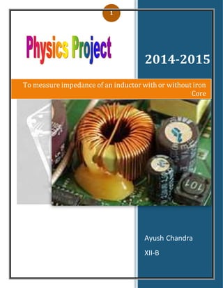
- 1. 1 2014-2015 Ayush Chandra XII-B To measure impedance of an inductor with or without iron Core
- 2. 2 Certificate This is to certify that Ayush Chandra student of class XII-B and Roll no: ___________________ of Lancers Convent School has completed the project titled “Impedance of an Inductor with and without iron core” during academic year 2014-2015 towards partial fulfillment of credit for the Physics practical evaluation of CBSE 2015 and submitted satisfactory report as compiled in the following pages under the supervision of Ms. Nushi Jain. .
- 3. 3 Signature:___________________ Acknowledgement I hereby express my gratitude to my Physics teacher Ms.Nushi Jain for their guidance throughout my studies. Their valuable guidance, support and supervision all through this project are responsible for attaining the present form. I thank my parents who supported me in all my endeavors. I also thank my classmates who have equally worked hard to make my project a success. And at last but not the least I thank the almighty for whatever I have achieved till now.
- 4. 4 Experiment Aim- To measure the resistance and impedance of an inductor with or without core APPRATUS AND MATERIAL 1. APPARATUS-A battery a high resistance rheostat, DC Ammeter, DC Voltmeter, one way key, variable output AC Source, AC Ammeter, AC Voltmeter, Connecting wires. 2. Material- A high resistance and large no of turns coil wrapped on a hollow cylindrical asbestos core, a soft iron rod fitting into the asbestos core THEORY An inductor, also called a coil or reactor, is a passive two terminal electrical component which resists changes in electric current passing through it. It consists of a conductor such as a wire, usually wound into a coil. When a current flows through it, energy is stored temporarily in a magnetic field in the coil. When the current flowing through an inductor changes, the time-
- 5. 5 varying magnetic field induces a voltage in the conductor, according to Faraday’s law of electromagnetic induction, which opposes the change in current that created it. Inductance (L) results from the magnetic field around a current-carrying conductor; the electric current through the conductor creates a magnetic flux. Mathematically speaking, inductance is determined by how much magnetic flux φ through the circuit is created by a given current i (1) For materials that have constant permeability with magnetic flux (which does not include ferrous materials) L is constant and (1) simplifies to Any wire or other conductor will generate a magnetic field when current flows through it, so every conductor has some inductance. The inductance of a circuit depends on the geometry of the current path as well as the magnetic permeability of nearby materials. In inductors, the wire or other conductor is shaped to increase the magnetic field. Winding the wire into a coil increases the number of times the magnetic flux lines link the circuit, increasing the field and thus the inductance. The more turns, the higher the inductance. The inductance also depends on the shape of the coil, separation of the turns, and many other factors. (1)ConstitutiveEQUATION
- 6. 6 Any change in the current through an inductor creates a changing flux, inducing a voltage across the inductor. By Faraday's law of induction, the voltage induced by any change in magnetic flux through the circuit is From (1) above (2) So inductance is also a measure of the amount of electromotive force (voltage) generated for a given rate of change of current. For example, an inductor with an inductance of 1 Henry produces an EMF of 1 volt when the current through the inductor changes at the rate of 1 ampere per second. This is usually taken to be the constitutive relation (defining equation) of the inductor. The dual of the inductor is the capacitor, which stores energy in an electric field rather than a magnetic field. Its current-voltage relation is obtained by exchanging current and voltage in the inductor equations and replacing L with the capacitance C. (2)Lenz's law The polarity (direction) of the induced voltage is given by Lenz's law, which states that it will be such as to oppose the change in current. For example, if the current through an inductor is increasing, the induced voltage will be positive at the terminal through which the current enters and negative at the
- 7. 7 terminal through which it leaves. The energy from the external circuit necessary to overcome this potential 'hill' is stored in the magnetic field of the inductor; the inductor is sometimes said to be "charging". If the current is decreasing, the induced voltage will be negative at the terminal through which the current enters. Energy from the magnetic field is being returned to the circuit; the inductor is said to be "discharging". (3)Inductor construction An inductor usually consists of a coil of conducting material, typically insulated copper wire, wrapped around a core either of plastic or of a ferromagnetic (or ferrimagnetic) material; the latter is called an "iron core" inductor. The high permeability of the ferromagnetic core increases the magnetic field and confines it closely to the inductor, thereby increasing the inductance. Low frequency inductors are constructed like transformers, with cores of electrical steel laminated to prevent eddy currents. Inductors come in many shapes. Most are constructed as enamel coated wire (magnet wire) wrapped around a ferrite bobbin with wire exposed on the outside, while some enclose the wire completely in ferrite and are referred to as "shielded". Inductors used to block very high frequencies are sometimes made by stringing a ferrite bead on a wire. Small inductors can be etched directly onto a printed circuit board by laying out the trace in a spiral pattern. Some such planar inductors use a planar core. Small value inductors can also be built on integrated circuits using the same processes that are used to make transistors. Procedure
- 8. 8 I Constructionofinductor-Using the drill bit as a template wrap the wire, counting up to the no of turns and keep the wire taught while turning. 1. When complete, snip off the reel at the 3cm distance from the last turn. 2. Use some needle nosed pliers to grip the coil on the bit as shown. Bend the legs as shown so that they are parallel. Remove from the drill bit. 3. The legs of the coil require tinning to remove the enamel and prime the surface for soldering onto the board. 4. Use some needle nosed pliers to grip the coil while tinning- it can be very hot. Heat one leg with the soldering iron for a few seconds. 5. Introduce some solder to the heated leg and continue applying the iron moving back and forth on the leg. 6. Continue adding solder until the leg is silvered all over. You will have to turn the coil over as you do this to ensure coverage. Coat any surplus solder and enamel to the end of the leg. 7. Repeat the procedure for the other leg. When complete, snip of the ends of the legs, with the surplus solder attached, leaving at least 1cm of straight leg before the turns. II Measurement ofresistance
- 9. 9 1. Clean the ends of the connecting wires with sand paper to remove the insulations, if any. 2. Make tight connections according to the circuit diagram. While making connections connect the inductor to the positive and negative ends of the battery and ensure that positive terminals of voltmeter and ammeter are joined towards the positive terminal of the battery. 3. Determine the least count of voltmeter an ammeter and voltmeter are working properly. 4. Adjust the sliding contact of the rheostat such that a small current passes through the resistance wire. 5. Note don the value of potential difference v from voltmeter and current I from ammeter. 6. Shift the rheostat contact slightly so that both ammeter and voltmeter show full divisions readings and not in fraction. Iii measurementofimpedancewithoutiron core 1. Disconnect the circuit and now connect the variable ac source is connected to AC mains, AC ammeter an AC voltmeter are used for measuring AC current and voltage. 2. The circuit will obey ohm’s law. The ratio of the voltmeter reading to the corresponding ammeter reading will give the impedance of the inductor without iron core. Iii measurementofimpedancewith iron core
- 10. 10 Now insert the iron core inside the hollowcylindrical asbestos core of the inductorwith iron core. OBSERVATION RECORD S.no Ammeter Reading Voltmeter Reading R=V/I Observed Corrected Observed Corrected 1 0.1 V 0.1 V 1.7 A 1.7 A 0.059Ω
- 11. 11 Measurementofresistanceandimpedance withoutiron core Measurementofresistanceandimpedancewithiron core S.no Ammeter Reading Voltmeter Reading R=V/I Observed Corrected Observed Corrected 1 0.1 V 0.1 V 1.6 A 1.6 A 0.062Ω 2 0.1 V 0.1 V 2 A 2 A 0.05 Ω 3 0.3 V 0.3 V 4 A 4 A 0.075Ω 4 0.4 V 0.4 V 6 A 6 A 0.06 Ω 2 0.1 V 0.1 V 3 A 3 A 0.033 Ω 3 0.3 V 0.3 V 5 A 5 A 0.06 Ω 4 0.4 V 0.4 V 7 A 7 A 0.057 Ω 5 0.5 V 0.5 V 8 A 8 A 0.062 Ω S.no (R)2 Z=(√𝑿 𝟐 + 𝒓 𝟐 (X=XL) 1 3.48 x 10⁻³ 1.46 Ω 2 1.08 x 10⁻³ 1.47 Ω 3 3.6 x 10⁻³ 1.58 Ω 4 3.26 x 10⁻³ 1.45 Ω 5 3.84 x 10⁻³ 1.52 Ω
- 12. 12 5 0.5 V 0.5 V 7 A 7 A 0.07 Ω Calculations 1.) Length of the wire=0.95 m 2.) Frequencyin India=50 Hz 1). Inductanceof L-R Circuit (L) = 𝜇𝑁2 𝐴 𝑙 = 𝜇 70 𝑋 70 𝑋 𝜋 1.7 𝑋 1.7 9.5 S.no (R)2 Z=(√𝑿 𝟐 + 𝒓 𝟐 ) (X=XL) 1 3.9 x 10⁻³ 1.54 Ω 2 2.5 x 10⁻³ 1.37 Ω 3 5.62 x 10⁻³ 1.71 Ω 4 4.35 x 10⁻³ 1.61 Ω 5 5.10 x 10⁻³ 1.68 Ω
- 13. 13 = 4𝜋X10−7X 4900 X 3.14 X 2.89 9.5 =0.0558 H 2.) Inductive Reactance=XL =2πνL =2 x 3.14 x 50 x 0.0558 =1.758 Ω Therefore (XL)2 =3.06 Ω 3) Mean Resistance without Iron Core=R1+R2+R3+R4+R5 =0.059+0.033+0.06+0.057+0.062 =0.054Ω 4) Mean Resistance with Iron Core=R1+R2+R3+R4+R5 =0.062+0.05+0.075+0.066+0.071 =0.064Ω 5) Mean impedance without Iron Core=Z1+Z2+Z3+Z4+Z5 =1.46+1.47+1.58+1.45+1.52Ω =1.496 Ω 5) Mean impedance with Iron Core=Z1+Z2+Z3+Z4+Z5 =1.54+1.37+1.71+1.61+1.68 = 1.582 Ω Result
- 14. 14 1.Total resistance of inductor with iron core =0.054 Ω 2.Total resistance of inductorwithout iron core =0.064 Ω 3.Total impedance of inductorwith iron core =1.496 Ω 4.Total impedance of inductorwithout iron core=1.582Ω Bibliography
- 15. 15 www.wikipedia.com APC Physics Manual