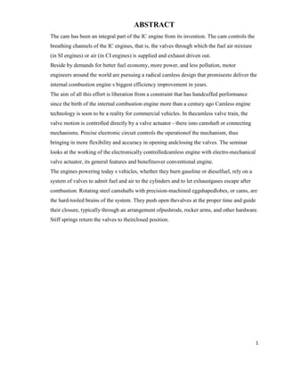
SlideShare ist ein Scribd-Unternehmen logo
1 von 22
ABSTRACT
The cam has been an integral part of the IC engine from its invention. The cam controls the
breathing channels of the IC engines, that is, the valves through which the fuel air mixture
(in SI engines) or air (in CI engines) is supplied and exhaust driven out.
Beside by demands for better fuel economy, more power, and less pollution, motor
engineers around the world are pursuing a radical camless design that promisesto deliver the
internal combustion engine s biggest efficiency improvement in years.
The aim of all this effort is liberation from a constraint that has handcuffed performance
since the birth of the internal combustion engine more than a century ago Camless engine
technology is soon to be a reality for commercial vehicles. In thecamless valve train, the
valve motion is controlled directly by a valve actuator - there isno camshaft or connecting
mechanisms. Precise electronic circuit controls the operationof the mechanism, thus
bringing in more flexibility and accuracy in opening andclosing the valves. The seminar
looks at the working of the electronically controlledcamless engine with electro-mechanical
valve actuator, its general features and benefitsover conventional engine.
The engines powering today s vehicles, whether they burn gasoline or dieselfuel, rely on a
system of valves to admit fuel and air to the cylinders and to let exhaustgases escape after
combustion. Rotating steel camshafts with precision-machined eggshapedlobes, or cams, are
the hard-tooled brains of the system. They push open thevalves at the proper time and guide
their closure, typically through an arrangement ofpushrods, rocker arms, and other hardware.
Stiff springs return the valves to theirclosed position.

1
CONTENTS
 INTRO
DUCTION

3

 WORKINGOF PUSH ROD ENGINE

4

Crankshaft
Camshaft
 Working

AN OVERVIEW OF CAMLESS ENGINE

7

Camless Valve Train
Hydraulic Pendulum
Valve Openinig& Closing
Valve Motion Control
Unequal Lift Modifier
Cylinder Head

COMPONENTS OF CAMLESS ENGINE

16

Engine Valve
Soleniod Valve
High Pressure pump
Low Pressure Pump
Cool Down Accumulator

 ADVANTAGES

20

 CONCLUSION22
 BIBLOGRAPHY

23

2
CAMLESS ENGINE
INTRODUCTION
The cam has been an integral part of the IC engine from its invention. The cam controls the
breathing channels´ of the IC engines,that is, the valves through which the fuel air mixture
(in SI engines) or air(in CI engines) is supplied and exhaust driven out. Besieged by
demandsfor better fuel economy, more power, and less pollution, motor engineersaround the
world are pursuing a radical camless´ design that promises to deliver the internal combustion
engines biggest efficiency improvementin years. The aim of all this effort is liberation from
a constraint that hashandcuffed performance since the birth of the internal combustion
enginemore than a century ago. Camless engine technology is soon to be areality for
commercial vehicles. In the camless valve train, the valvemotion is controlled directly by a
valveactuator there is no camshaft or connecting mechanisms .Precise electrohydraulic
camlessvalve traincontrols the valve operations, opening, closing etc. The seminar looks at
the working of the electrohydraulic camless engine, its general features and benefits over
conventional engines. The engines powering todays vehicles, whether they burn gasoline or
diesel fuel, rely on a system of valves to admit fuel and air to the cylinders and let exhaust
gases escape after combustion. Rotating steel camshafts with precision machined egg shaped
lobes, or cams, are the hard-tooled brains´ of the system. They
push open the valves at the proper time and guide their closure, typically through an
arrangement of pushrods, rocker arms, and other hardware.
Stiff springs return the valves to their closed position. In an overhead camshaft engine, a
chain or belt driven by the crankshaft turns one or two camshafts located atop the cylinder
head.
A single overhead camshaft (SOHC) design uses one camshaft to move rockers that open
both inlet and exhaust valves. The double overhead camshaft (DOHC), or twin-cam, setup
does away with the rockers and devotes one camshaft to the inlet valves and the other to the
exhaust valves.

3
WORKING OF PUSH ROD ENGINE
Pushrod engines have been installed in cars since the dawn of the horseless carriage. A
pushrod is exactly what its name implies. It is a rod that goes from the camshaft to the top of
the cylinder head which push open the valves for the passage of fuel air mixture and exhaust
gases.
Each cylinder of a pushrod engine has one arm (rocker arm) that operates the valves to bring
the fuel air mixture and another arm to control the valve that lets exhaust gas escape after the
engine fires. There are several valve train arrangements for a pushrod.

Figure1.Working of push rod engine

Crankshaft
Crankshaft is the engine component from which the power is taken. It receives the power
from the connecting rods in the designated sequence for onward transmission to the clutch
and subsequently to the wheels. The crankshaft assembly includes the crankshaft and
bearings, the flywheel, vibration damper, sprocket or gear to drive camshaft and oil seals at
the front and rear.

Camshaft
The camshaft provides a means of actuating the opening and controlling the period before
closing, both for the inlet as well as the exhaust valves, it also provides a drive for the
ignition distributor and themechanical fuel pump.
The camshaft consists of a number of cams at suitable angular positions for operating the
valves at approximate timings relative to the piston movement and in the sequence
according to the selected firing order. There are two lobes on the camshaft for each cylinder
of the engine; one to operate the intake valve and the other to operate the exhaust valve.
4
Working
When the crank shaft turn the cam shaft the cam lobs come up under the valve lifter and
cause the lifter to move upwards. The upward push is carried by the pushrods through the
rocker arm. The rocker arm is pushed by the pushrod, the other end moves down. This
pushes down on the valve stem and cause it to move down thus opening the port. When the
cam lobe moves out from under the valve lifter, the valve spring pulls the valve back upon
its seat. At the same time stem pushes up on the rocker arm, forcing it to rock back. This
pushes the push rods and the valve lifter down, thus closing the valve. The figureshows camvalve arrangement in conventional engines.

Figure-2.Cam-valve arrangement in conventional engines

Single cam and valve conventional valve train mechanism
Since the timing of the engine is dependent on the shape of the cam lobes and the rotational
velocity of the camshaft, engineers must make decisions early in the automobile
development process that affect the engines performance. The resulting design represents a
compromise between fuel efficiency and engine power. Since maximum efficiency and
maximum power require unique timing characteristics, the cam design must compromise
between the two extremes. This compromise is a prime consideration when consumers
purchase automobiles. Some individuals value power and lean toward the purchase of a high
performance sports car or towing capable trucks, while others value fuel economy and
vehicles that will provide more miles per gallon.
Recognizing this compromise, automobile manufacturers have been attempting to provide
vehicles capable of cylinder deactivation, variable valve timing (VVT), or variable camshaft
timing (VCT). These new designs are mostly mechanical in nature. Although they do
providean increased level of sophistication, most are still limited to discrete valve timing
changes over a limited range.
5
SENSORS ACTUATORS
AN OVERVIEW OF CAMLESS ENGINE
To eliminate the cam, camshaft and other connected mechanisms, the Camless engine makes
use of three vital components and the sensors, the electronic control unit and the actuator

ELECTRONICCONTROLUNIT
Mainly five sensors are used in connection with the valve operation. One for sensing the
speed of the engine, one for sensing the load on the engine, exhaust gas sensor, valve
position sensor and current sensor. The sensors will send signals to the electronic control
unit.
The electronic control unit consists of a microprocessor, which is provided with a software
algorithm. The microprocessor issues signals to the solid-state circuitry based on this
algorithm, which in turn controls the actuator, to function according to the requirements.

Camless valve train
In the past, electro hydraulic camless systems were created primarily as research tools
permitting quick simulation of a wide variety of cam profiles. For example, systems with
precise modulation of a hydraulic actuator position in order to obtain a desired engine valve
lift versus time characteristic, thus simulating the output of different camshafts. In such
systems the issue of energy consumption is often unimportant. The system described here
has been conceived for use in production engines. It was, therefore, very important to
minimize the hydraulic energy consumption.

1. Electromechanical Poppet Valves
This type of system uses an armature attached to the valve system. The outside casing
contains a magnetic coil of some sort that can be used to either attract or repel the armature,
hence opening or closing the valve.
Most early systems employed solenoid and magnetic attraction/repulsion actuating
principals using an iron or ferromagnetic armature. These types of armatures limited the
performance of the actuator because they resulted in a variable air gap. As the air gap
becomes larger (i.e when the distance between the moving and stationary magnets or
electromagnets increases), there is a reduction in the force. To maintain high forces onthe
armature as the size of the air gap increases, a higher current is employed in the coils of such
devices. This increased current leads to higher energy losses in the system, not to mention
non-linear behavior that makes it difficult to obtain adequate performance. The result of this
6
is that most such designs have high seating velocities (ie the valves slam open and shut
hard!) and the system cannot vary the amount of valve lift.
The electromechanical valve actuators of the latest poppet valve design eliminate the iron or
ferromagnetic armature. Instead it is replaced with a current-carrying armature coil. A
magnetic field is generated by a magnetic field generator and is directed across the fixed air
gap. An armature having a current-carrying armature coil is exposed to the magnetic field in
the air gap. When a current is passed through the armature coil and that current is
perpendicular to the magnetic field, a force is exerted on the armature.When a current runs
through the armature coil in either direction and perpendicular to the magnetic field, an
electromagnetic vector force, known as a Lorentz force, is exerted on the armature coil. The
force generated on the armature coil drives the armature coil linearly in the air gap in a
direction parallel with the valve stem. Depending on the direction of the current supplied to
the armature coil, the valve will be driven toward an open or closed position. These
latest electromechanical valve actuators develop higher and bettercontrolled
forces than those designs mentioned previously. These forces are constant along the distance
of travel of the armature because the size of the air gap does not change.
The key component of the Siemens-developed infinitely variable electromechanical valve
train is an armature-position sensor. This sensor ensures the exact position of the armature is
known to the ECU at all times and allows the magnetic coil current to be adjusted to obtain
the desired valve motion.
Referring now to Figure 1 an electromechanical valve actuator of the poppet valve variety is
illustrated in conjunction with an intake or exhaust valve. The valve includes a valve closure
member having a cylindrical valve stem and a cylindrical valve head attached to the end of
the stem. The valve actuator of the poppet valve system generally includes a housing
assembly consisting of upper and lower tubular housing members and , a magnetic field
generator consisting of upper and lower field coils and a core consisting of upper and lower
core member and , and an armature suitably connected to the valve stem .
The armature coil is preferably made from aluminium wire or other electrically conductive
lightweight material, which is highly conductive for its mass. Minimising the armature mass
is especially important in view ofthe rapid acceleration forces placed on it in both directions.
The ability of the electromechanical valve actuator to generate force in either direction and
to vary the amount of force applied to the armature in either direction is an important
advantage of this design. For instance, varying the value of the current through the armature
7
coil and/or changing the intensity of the magnetic field can control the speed of opening and
closing of the valve. This method can also be used to slow the valve closure member to
reduce the seating velocity, thereby lessening wear as well as reducing the resulting noise.
This system is able to operate without valve springs as shown in Figure 1 or can equally be
equipped with them as shown in Figures.
Siemens report that a special software algorithm is used to control the actuator coil currents
such that the valves are decelerated to a speed near zero as they land - in conjunction with a
switching time of barely three milliseconds. For the valves this means minimal wear and
minimum noise generation. The 16-valve four cylinder engine that is currently undergoing
tests in Germany, by Siemens, is equipped with 16 valve actuators and the corresponding
armature-position sensors. A Siemens ECU is used and two cable rails connect the actuators
to it. A 42-volt starter-generator provides the power.

Figure-3. Electromechanical Poppet Valves

2. Electromechanical Ball Valves
An alternative to theconventional poppet valve for use incamless valve trains is a ball
valve.This type of electromechanical valve system consists of a ball through which a
passage passes. If the ball is rotated such that the passage lines up with other openings in the
valve assembly, gas can pass through it. (Exactly like the ball valves many of us use valve is
accomplished by electromagnets positioned around its exterior. to control our boost.
Opening and closing the Referring to Figure , the valve housingis shown in two pieces. Ball
valve has two rigidly attached pivots . The disc is permanently attached and indexed to the
8
ball valve and contains permanent magnets around its perimeter. The electromagnets are
situated on both sides of the ball valve and they are fixed tothe valve housing. The
electromagnets are controlled through the ECU. A crank trigger sensor on the crankshaft
provides information about the position of the pistons relative to top dead centre. Thus, at
top dead centre of the power stroke, the ECM could be used to fix the polarity of both
electromagnets so that they are of opposite polarity to the magnets in the ball valve, rotating
the ball valve to the closed position.
The substitution of a simple, efficient ball valve and valve housing arrangement in aa four
stroke reciprocation piston engine eliminates all the independent moving parts in the valve
train. This may even be an improvement over the poppet valve camless system - the ball
valve needs only to rotate on its axis to achieve the desired flow conditions, rather than be
accelerated up and down in a linear fashion. A partially open ball valve state may also be
able to be used to create more turbulence.
Electromechanical valve train implementation would not be possible with a normal 12V
electrical system. As has been covered previously in AutoSpeed ("Goodbye 12 volts... hello
42 volts!"), the automotive industry has chosen a 42V electrical system as the next
automotive standard. Consequently, the energy demand of EMVT can be optimally matched
by a crankshaft-mounted starter-generator (KSG - in Siemens speak) operating at 42V; it is
integrated in the flywheel and designed for the starting process as well as generator
operation.

Electrohydraulic Poppet Valves
In general terms, present designs of electrohydraulic valves comprise poppet valves
moveable between a first and second position. Used is a source of pressurised hydraulic
fluid and a hydraulic actuator coupled to the poppet valve. The motion between a first and
second position is responsive to the flow of the pressurised hydraulic fluid. An electrically
operated hydraulic valve controls the flow of the pressurised hydraulic fluid to the hydraulic
actuator. In one design, the provision is made for a three-way electrically operated valve to
control the flow of the pressurized hydraulic fluid to the actuator. This supplies pressure
when electrically pulsed open, and dumps actuator oil to the engine oil sump when the valve
is electrically pulsed to close. The use of engine oil as the hydraulic fluid simplifies and
lowers the cost of the design by removing the need for a separate hydraulic system. The
basic design of the electrohydraulic valvetrain hardware is illustrated in Figure. The engine
poppet valves and the valve springs that are used to reset them are shown. The poppet
9
valves are driven by hydraulic actuators , which are controlled by electrically operated
electro-hydraulic valves supplying hydraulic fluid to the actuators via conduit . The
preferred hydraulic fluid is engine oil, supplied to the electro-hydraulic valves by the
pressure rail. An engine-driven hydraulic pump supplies the oil pressure, receiving the oil
from the engine oil sump . The pump output pressure is also limited by an unloadervalve, as
controlled by an accumulator connected tothe oil pressure rail. With this design the
hydraulic pump could be periodically disconnected, such as under braking, so that the valve
train would run off the stored accumulator hydraulic pressure.
As is the trend with all modern engine systems, the camless engine has an even greater
reliance on sensors. The valve actuation and control system typically needs a manifold
pressure sensor, a manifold temperature sensor, a mass flow sensor, a coolant temperature
sensor, a throttle position sensor, an exhaust gas sensor, a high resolution engine position
encoder, a valve/ignition timing decoder controller, injection driver electronics, valve coil
driver electronics, ignition coil driver electronics, air idle speed control driver electronics
and power down control electronics.
A valve developed by Sturman Industries is said to be about six times faster than
conventional hydraulic valves. To achieve such speeds, it uses a tiny spool sandwiched
between two electrical coils. By passing current back and forth between the coils, a
microprocessor -based controller can quickly move the spool back and forth, thereby
actuating the engine valves in accordance.
However, electrohydraulic systems are mostly being developed for diesel truck use because
it is currently not clear whether the technology will have the speed needed for higher
revving passenger car engines.

Figure-4. Electrohydraulic Poppet Valves
10
Valve opening and closing
A more detailed step-by-step illustration of the valve opening and closing process is given in
Figure . It is a six-step diagram, and in each step an analogy to a mechanical pendulum is
shown. In Step 1 the opening (high pressure) solenoid valve is opened, and the high-pressure
fluid enters thevolume above the valve piston. The pressure above and below the
pistonbecome equal, but, because of the difference in the pressure areas, the constant net
hydraulic force is directed downward. It opens the valve and accelerates it in the direction of
opening. The other solenoid valve and the two check valves remain closed. In Step 2 the
opening solenoid valve closes and the pressure above the piston drops, but the engine valve
continues its downward movement due to its momentum. The low pressure check valve
opens and the volume above the piston is filled with the low-pressure fluid. The downward
motion of the piston pumps the high-pressure fluid from the volume below the piston back
into the high pressure rail. This recovers some of the energy that was previously spent to
accelerate the valve. The ratio of the high and low-pressures is selected so, that the net
pressure force is directed upward and the valve decelerates until it exhausts its kinetic
energy and its motion stops. At this point, the opening check valve closes, and the fluid
above the piston is trapped. This prevents the return motion of the piston, and the engine
valve remains fixed in its open position trapped by hydraulic pressures on both sides of the
piston. This situation is illustrated in Step 3, which is the open dwell position. The engine
valve remains in the open dwell position as long as necessary. Step 4 illustrates the
beginning of the valve closing.
The closing (low-pressure) solenoid valve opens and connects the volume above the piston
with the low-pressure rail. The net pressure force is directed upward and the engine valve
accelerates in the direction of closing, pumping the fluid from the upper volume back into
the low pressure reservoir. The other solenoid valve and both check valves remain closed
during acceleration. In Step 5 the closing solenoid valve closes and the upper volume is
disconnected from the low-pressure rail, but the engine valve continues its upward motion
due to its momentum.
Rising pressure in the upper volume opens the high-pressure check valve that connects this
volume with the high-pressure reservoir. The upward motion of the valve piston pumps the
fluid from the volume above the piston into the high-pressure reservoir, while the increasing
volume below the piston is filled with fluid from the same reservoir. Since the change of
11
volume below the piston is only a fraction of that above the piston, the net flow of the fluid
is into the high-pressure reservoir. Again, as it was the case during the valve opening,
energy recovery takes place. Thus, in this system the energy recovery takes place twice each
valve event.
When the valve exhausts its kinetic energy, its motion stops, and the check valve closes.
Ideally, this should always coincide with the valve seating on its seat. This, however, is
difficult to accomplish. A morepractical solution is to bring the valve to a complete stop a
fraction of a millimeter before it reaches the valve seat and then, briefly open the closing
solenoid valve again. This again connects the upper volume with the however, is difficult to
accomplish. A more practical solution is to bring the valve to a complete stop a fraction of a
millimeter before it reaches the valve seat and then, briefly open the closing solenoid valve
again. This again connects the upper volume with the low-pressure reservoir, and the high
pressure in the lower volume brings the valve to its fully closed position. Step 6 illustrates
the valve seating. After that, the closing solenoid valve is deactivated again. For the rest of
the cycle both solenoid valves and both check valves are closed, the pressure above the
valve piston is equal to the pressure in the low-pressure reservoir, and the high pressure
below the piston keeps the engine valve firmly closed.

Valve motion control
Varying the activation timing of both solenoids varies the timing of the engine valve
opening and closing. This of course, also vanes the valve event duration. Valve lift can be
controlled by varying the duration of the solenoid voltage pulse. Changing the high pressure
permits control of the valve acceleration, velocity, and travel time. The valve can be
deactivated during engine operation by simply deactivating the pair of solenoids which
control it. Deactivation can last any number of cycles and be as short, as one cycle.
Increasing the number of valves in each cylinder does not require a corresponding increase
in the number of solenoid valves. The same pair of solenoid valves, which controls a single
valve, can also control several valves running in-parallel. Thus, in a four-valve engine a pair
of solenoid valves operates two synchronously running intake valves, and another
pair runs the two exhaust valves.
UNEQUAL LIFT MODIFIER - In a four-valve engine an actuator setconsisting of two
solenoid valves and two check valves controls the operation of a pair of intake or a pair of
exhaust valves. Solenoids and check valves are connected to a common control chamber
serving both valves. In a four-cylinder engine there is a total of eight control chambers
12
connected to eight pairs of valves. For each pair, the volumes below the hydraulic pistons
are connected to the high pressure reservoir via a device called the lift modifier. In a neutral
position the modifier does not affect the motion of the valves, and activation of the solenoid
valves moves both engine valves in unison.

Figure 5.Paired valves with unequal lift control.
To enhance the ability to vary the intake air motion in the enginecylinder, it is often
desirable to have unequal lift of the two intake valves, or even to keep one of the two valves
closed while the other opens. In some cases it may also be used for paired exhaust valves.
The lift modifier is then used to restrict the opening of one the paired valves. The modifier is
shown schematically in Figure as a Rotating rod with its axis of rotation perpendicular to the
plane of the drawing. The rod is installed in the cylinder head between the two intake valves.
A cutout in the rod forms a communication chamber connected to the volumes below the
hydraulic pistons of both intake valves. The communication chamber is always connected to
the high pressure reservoir. In the case A the modifier is in the neutral position, and both
valves operate in unison. In the case B the modifier rod is shown turned 90 degrees
clockwise. The exit of oil from the volume below the hydraulic piston in the valve No. 1 is
blocked and the valve cannot move in the direction of opening. However, the entry of oil
into the volume below the hydraulic piston is permitted by a one-way valve installed in the
modifier rod. This guarantees that, whenever deactivation takes place, the valve No. 1 will
close and remain closed, while the valve No.2 continues its normal operation. If the modifier
rod is turned 90 degrees counter-clockwise (from the position shown in the case A), the
valve No.2 is deactivated, while the valve No. 1 would continue normal operation. In the
case C the lift of one of the valves is reduced relative to the second one. The rod is turned a
13
smaller angle so that the exit of oil from the valve No. 1 into the communication chamber is
not completely blocked, but the flow is significantly throttled.
As a result, the motion of the valve No. 1 is slowed down and its lift is less than that of the
valve No.2. Varying the angular position of the modifier rod 26 varies the degree of oil
throttling, thus varying the lift of the valve No. 1.

Figure 6.Unequal lift control.

DESIGN APPROACH FOR CAMLESS ENGINE
The camless engine was created on the basis of an existing four cylinder, four-valve engine.
The original cylinder head with all the valves, springs, camshafts, etc. was replaced by a
new cylinder head assembly fully integrated with the camless valve train. The camshaft
drive was eliminated, and a belt-driven hydraulic pump was added. There was no need for
lubrication, and the access for engine oil from the engine block to the cylinder head was
closed off. No other changes to the engine have been made.

Cylinder head
Two cross sections of the cylinder head are shown in Figure. Thealuminum casting is within
the original confines and contains all hydraulicpassages connecting the system components.
The high- and low-pressurehydraulic reservoirs are integrated into the casting. The
reservoirs andthe passages occupy the upper levels of the cylinder head and are part of
the hydraulic system. The hydraulic fluid is completely separated from the engine oilsystem.
A finite element analysis was used to assure the cylinder head integrity for fluid pressures of
up to 9 Mpa. The lower level of the head contains the engine coolant.
14
Figure 7.Cross sections of cylinder head.
The engine valves, the check valves and the modifiers are completely buried in the body of
the head. The solenoid valves are installed on the top of the cylinder head and are kept in
their proper locations by a cylinder head cover. Hydraulic and electric connections leading
to the hydraulic pump and the electronic controller, respectively, are at the back end of the
cylinder head. The height of the head assembly is approximately 50 mm lower than the
height of the base engine head. Figure 13 is a photograph of the head on the engine with the
head cover removed.

COMPONENTS OF CAMLESS ENGINE
Main components of a camless engine are-Engine valve, solenoid valve, high pressure
pump, low pressure pump, cool down accumulator, etc.

Engine valve: A cross section of the engine valve assembly is shown in Figure. The valve
piston is attached to the top of the valve, and both the valve and the piston can slide inside a
sleeve. The sleeve openings above and below the valve piston allow the hydraulic fluid to
enter and exit. A seal in the lower part of the sleeve prevents leakage of fluid into the intake
or exhaust port. A leak-off (not shown) unloads the
seal from excessive pressure, which otherwise increases friction. There is a tight hydraulic
clearance between the valve and the sleeve. However ,the clearance between the sleeve and
the cylinder head is relatively large, which improves the centering of the valve in its seat
Circulation of hydraulic fluid through the chambers above and below the valve piston cools
and lubricates the valve. All the forces acting on the valve are directed along its axis.
Absence of side forces reduces stresses, friction and wear.

15
Figure 8. Engine valve
Solenoid valve : Figure shows a cross section of the solenoidvalve. The solenoid has
conically shaped magnetic poles. This reduces the air gap at a given stroke. The normallyclosed valve is hydraulically balanced during its movement. Only a slight unbalance exists
in the fully open and the fully-closed positions. A strong spring is needed to obtain quick
closing time and low leakage between activations. The hydraulic energy loss is the greatest
during the closing of either the high- or the low-pressure solenoid, because it occurs during
the highest piston velocity. Thus, the faster the solenoid closure, the better the energy
recovery. The valve lift and the seat diameter are selected to minimize the hydraulic loss
with a large volume of fluid delivered during each opening. Both high-pressure and low
pressure solenoid valves are of the same design.

Figure 9.Solenoid valve.
16
Lift modifier - The design of the lift modifier permits a simultaneous hydraulic control of a
group of modifiers with a single pulse-width modulated solenoid-valve that adjusts the
pressure in a control gallery.
Hydraulic system
A diagram of the hydraulic system is shown in Figure. An engine driven variabledisplacement pump automatically adjusts its output to maintain the required pressure. The
high-pressure and the low-pressure reservoirs are connected to all corresponding locations
serving the high and the low-pressure solenoids and the check valves.
High pressure pump: The quantity of fluid delivered by the high pressure pump with the
actual needs of the system at various engine speeds and loads is critical to assuring low
energy consumption. To conserve the mechanical power needed to drive the pump, its
hydraulic output should closely match the needs. A variable displacement, high efficiency,
axial plunger-type pump was initially selected for that reason.
Taking into account the prohibitively high cost of such pump for automotive applications, a
low-cost variable capacity pump was conceived. A cross section of the pump is shown in
Figure. The pump has a single eccentric-driven plunger and a single normally-open solenoid
valve. During each down stroke of the plunger the solenoid valve is open, and the plunger
barrel is filled with hydraulic fluid from the low pressure branch of the system. During the
upstroke of the plunger, the fluid is pushed back into the low pressure branch, as long as the
solenoid valve remains open. Closing the solenoid valve causes the plunger to pump thefluid
through a check valve into the high pressure branch of the system.
Varying the duration of the solenoid voltage pulse varies the quantity of the high-pressure
fluid delivered by the pump during each revolution.

Figure 10.High pressure pump.
17
Low pressure pump - A small electrically driven pump picks upoil from the sump and
delivers it to the inlet of the main pump. Only a small quantity of oil is required to
compensate for the leakage through the leak-off passage, and to assure an adequate inlet
pressure for the main pump. Any excess oil pumped by the small pump returns to the sump
through a low-pressure regulator. A check valve 1 assures that the inlet to the main pump is
not subjected to pressure fluctuations that occur in the low-pressure reservoir.
Cool down accumulator - The system also includes a cool down accumulator that, during
normal operation, is fully charged with oil under the same pressure as in the inlet to the main
pump. When the engine stops running, the oil in both the high- and the low-pressure
branches cools off and shrinks. As the system pressure drops, the accumulator discharges oil
into the system, thus compensating for the shrinkage and preventing formation of pockets of
oil vapor. The high - pressure branch is fed from the accumulator through a check valve 2
that is installed in-parallel to the main pump. The low-pressure branch is fed through an
orifice that is installed in-parallel to the check valve 1. The orifice is small enough to
prevent pressure wave propagation through it during each engine cycle, but sufficient to
permit slow flow of oil from the accumulator to the reservoir. In some applications, the
orifice can be incorporated directly in the check valve. After the oil in the system has cooled
off, the accumulator maintains the system at above atmospheric pressure by continuously
replenishing the oil that slowly leaks out through the leak-off passage. When the engine is
restarted, the accumulator is recharged again. If the engine is not restarted for a very long
time, as it is the case when a vehicle is left in a long-term parking, the accumulator will
eventually become fully discharged. In that case, the pressure in the accumulator drops to an
unacceptable level, and a pressure sensor, that monitors the accumulator pressure, sends a
signal to the engine control system which reactivates the electric pump for a short period of
time to recharge the accumulator. This process can be repeated many times, thus
maintaining the system under a low level of pressure until the engine is restarted. After the
engine restarts it takes less than one revolution of the main pump to restore the high
pressure. Operating the hydraulic system in a closed loop contributes to low energy
consumption. The amount of hydraulic power consumed by the system is determined by the
flow offluid from the high- to the low-pressure reservoir times the pressure differential
between the outlet from and the inlet to the high pressure pump. A small loss is also
associated with leakage. There are good reasons to use high hydraulic pressure in the
system, one of them being the need to maintain a high value of the bulk modulus of the oil.
18
In a closed-loop system the pressure in the low-pressure reservoir can also be quite
high,although lower than in the high-pressure reservoir (thus the pressure in the lowpressure rail is low only in relative terms). Hence, the system can operate with very high
hydraulic pressure, and yet the energy consumption remains modest due to a relatively low
pressure differential.
The ratio of high pressure to low pressure must be sufficiently higher than the ratios of the
pressure areas above and below the valve piston to assure reliable engine valve closure.
ADVANTAGES OF CAMLESS ENGINE
Electro hydraulic camless valve train offers a continuously variable and independent control
of all aspects of valve motion. This is a significant advancement over the conventional
mechanical valve train. It brings about a system that allows independent scheduling of valve
lift, valve open duration, and placement of the event in the engine cycle, thus creating an
engine with a totally uncompromised operation. Additionally, the ECV system is capable of
controlling the valve velocity, perform selective valve deactivation, and vary the activation
frequency. It also offers advantages in packaging. Freedom to optimize all parameters of
valve motion for each engine operating condition without compromise is expected to result
in better fuel economy, higher torque and power, improved idle stability, lower exhaust
emissions and a number of other benefits and possibilities. Camless engines have a number
of advantages over conventional engines.
In a conventional engine, the camshaft controls intake and exhaust valves. valve timing,
valve lift, and event duration are all fixed values specific to the camshaft design. The cams
always open and close the valves at the same precise moment in each cylinders constantly
repeated cycle of fuel-air intake, compression, combustion, and exhaust.
They do so regardless of whether the engine is idling or spinning at maximum rpm. As a
result, engine designers can achieve optimum performance at only one speed. Thus, t he
camshaft limits engine performance in that timing, lift, and duration cannot be varied.
The improvement in the speed of operation valve actuation and control system can be
readily appreciated with reference to Figure . It shows a comparison between valve speeds
of a mechanical camshaft engine and the camless engine valve actuation. The lengthof the
valve stroke ininches versus degrees of rotation of a mechanical camshaft is illustrated.
When graphed, the cycle of opening and closing of a valve driven by a mechanical camshaft
will display a shape similar to a sine curve. The opening period (as measured in crankshaft
degrees) remains constant for any engine load or rpm. However, the cycle of opening and
19
closing of valves driven by the electromechanical valve actuators operates much faster.
Designed to match valve-opening rates at the maximum engine rpm, the electromechanical
valve actuators open the valve at this same rate regardless of engine operating conditions.
Because of this improved speed, greater flexibility in programming valve events is possible,
allowing for improved low-end torque, lower emissions and improved fuel economy. The
massive opening period for the electromechanically driven valve can also be seen But in a
cam less engine, any engine valve can be opened at any time to any lift position and held for
any duration, optimizing engine performance. The valve timing and lift is controlled 100
percent by a microprocessor, which means lift and duration can be changed almost infinitely
to suit changing loads and driving 0conditions. The promise is less pollution, better fuel
economy and performance.
Another potential benefit is the cam less engines fuel savings. Compared to conventional
ones, the cam less design can provide a fuel economy of almost 7- 10% by proper and
efficient controlling of the valve lifting and valve timing. The implementation of camless
design will result in considerable reduction in the engine size and weight. This is achieved
by the elimination of conventional camshafts, cams and other mechanical linkages. The
elimination of the conventional camshafts, cams and other mechanical linkages in the
camless design will result in increased power output.
The better breathing that a camless valve train promotes at low engine speeds can yield 10%
to 15% more torque. Camless engines can slash nitrogen oxide, or Ox, pollution by about
30% by trapping some of the exhaust gases in the cylinders before they can escape.
Substantially reduced exhaust gas HC emissions during cold start and warm -up
operation.

20
CONCLUSIONS
1. An electro hydraulic camless valve train was developed for a camlessengine. Initial
development confirmed its functional ability to control the valve timing, lift, velocity, and
event duration, as well as to perform selectively variable deactivation in a four –valve
multicylinderengine.
2. The system employs the hydraulic pendulum principle, which contributes to low
hydraulic energy consumption.
3. The electro hydraulic valve train is integral with the cylinder head, which lowers the head
height and improves the engine packaging.
4. Review of the benefits expected from a camless engine points to substantial
improvements in performance, fuel economy, and emissions over and above what is
achievable in engines with camshaftbasedvalve trains.
5. The development of a camless engine with an electro hydraulic valve train described in
this report is only a first step towards a complete engine optimization. Further research and
development are needed to take full advantage of this system exceptional flexibility.

21
BIBLIOGRAPHY :Michael M.Schechter and Michael B.Levin‘Camless Engine´ SAE paper 960581
P. reuter, P. Heuser, and M. Schebitz, Strategies to ImpoveSIEnginePerformance by Means
of ariable Intake Lift, Timing and Duration , SAE paper 920449. K. Hatano, k. Lida, H.
Higashi, and S. Murata, Development of a ew Multi-Mode ariablealve Timing
Engine´,SAEpaper930878
J-C.Lee, C-W. Lee, and J. itkiewitz, The Application of a Lost Motion T System to a DOHC
SI Engine´,SAE paper 950816
John B. Heywood, Internal combustion engine fundamentals´ William H. crouse.
Automotive mechanics.´
John Steven Brader ,A Thesis on Development of a Piezoelectric Controlled Hydraulic
Actuator for a Camless Engine
www.machinedesign.com
www.halfbakery.com
www.deiselnet.com
www.greendieseltechnology.co
www.me.sc.edu

22

Weitere ähnliche Inhalte

Was ist angesagt?

Camless engines
Camless enginesCamless engines
Camless engines
Mani Kanta
 
Halderman ch032 lecture
Halderman ch032 lectureHalderman ch032 lecture
Halderman ch032 lecture
mcfalltj
 
Variable speed hydraulic drive
Variable speed hydraulic driveVariable speed hydraulic drive
Variable speed hydraulic drive
mitravanu mishra
 

Was ist angesagt? (20)

Camless engines
Camless enginesCamless engines
Camless engines
 
CAMLESS ENGINE
CAMLESS ENGINECAMLESS ENGINE
CAMLESS ENGINE
 
Soil sieve analysis
Soil sieve analysisSoil sieve analysis
Soil sieve analysis
 
Camless engines
Camless enginesCamless engines
Camless engines
 
Cam-Less Engines
Cam-Less EnginesCam-Less Engines
Cam-Less Engines
 
Freevalve share
Freevalve shareFreevalve share
Freevalve share
 
Internal Combustion Engines - Variable valve lift
Internal Combustion Engines - Variable valve liftInternal Combustion Engines - Variable valve lift
Internal Combustion Engines - Variable valve lift
 
Variable valve timing in internal combustion engine
Variable valve timing in internal combustion engineVariable valve timing in internal combustion engine
Variable valve timing in internal combustion engine
 
Koenigsegg cam-less engine
Koenigsegg cam-less engineKoenigsegg cam-less engine
Koenigsegg cam-less engine
 
Variable Valve Timing (VVT)
Variable Valve Timing (VVT)Variable Valve Timing (VVT)
Variable Valve Timing (VVT)
 
VALVE MECHANISM BY G.DINESHPIRAN
VALVE MECHANISM BY G.DINESHPIRANVALVE MECHANISM BY G.DINESHPIRAN
VALVE MECHANISM BY G.DINESHPIRAN
 
How Did Valvetronic Engine Technology With BMW Become The Best..
How Did Valvetronic Engine Technology With BMW Become The Best..How Did Valvetronic Engine Technology With BMW Become The Best..
How Did Valvetronic Engine Technology With BMW Become The Best..
 
Future valve system in engine
Future valve system in engineFuture valve system in engine
Future valve system in engine
 
Halderman ch032 lecture
Halderman ch032 lectureHalderman ch032 lecture
Halderman ch032 lecture
 
Camless Engines
Camless EnginesCamless Engines
Camless Engines
 
Gagan.Ppt
Gagan.PptGagan.Ppt
Gagan.Ppt
 
Design Of A Throttleless Engine For A F 1502
Design Of A Throttleless Engine For A F 1502Design Of A Throttleless Engine For A F 1502
Design Of A Throttleless Engine For A F 1502
 
Multi air engine[ jasim2
Multi air engine[ jasim2Multi air engine[ jasim2
Multi air engine[ jasim2
 
Variable speed hydraulic drive
Variable speed hydraulic driveVariable speed hydraulic drive
Variable speed hydraulic drive
 
Basic Significance of Variable Valve Timing Engine
Basic Significance of Variable Valve Timing EngineBasic Significance of Variable Valve Timing Engine
Basic Significance of Variable Valve Timing Engine
 

Andere mochten auch

Introduction to Pumps
Introduction to PumpsIntroduction to Pumps
Introduction to Pumps
mohdalaamri
 

Andere mochten auch (11)

Acc03 tai
Acc03 taiAcc03 tai
Acc03 tai
 
Sturman engines camless digital engines overview article
Sturman engines camless digital engines overview articleSturman engines camless digital engines overview article
Sturman engines camless digital engines overview article
 
A synopysis report on pedal operated washing machine
A synopysis report on pedal operated washing machineA synopysis report on pedal operated washing machine
A synopysis report on pedal operated washing machine
 
Report on advances in tribology
Report on advances in tribologyReport on advances in tribology
Report on advances in tribology
 
Proceedings of a Workshop on Hydraulic Ram Pump Technology - International De...
Proceedings of a Workshop on Hydraulic Ram Pump Technology - International De...Proceedings of a Workshop on Hydraulic Ram Pump Technology - International De...
Proceedings of a Workshop on Hydraulic Ram Pump Technology - International De...
 
Slider Crank Mechanism for Four bar linkage
Slider Crank Mechanism for Four bar linkageSlider Crank Mechanism for Four bar linkage
Slider Crank Mechanism for Four bar linkage
 
Slider crank
Slider crankSlider crank
Slider crank
 
Turning moment diagrams
Turning moment diagramsTurning moment diagrams
Turning moment diagrams
 
Pedal Powered Water Pump
Pedal Powered Water PumpPedal Powered Water Pump
Pedal Powered Water Pump
 
Introduction to Pumps
Introduction to PumpsIntroduction to Pumps
Introduction to Pumps
 
Kinematics of machines,rotating rigid body about axis,
Kinematics of machines,rotating rigid body about axis,Kinematics of machines,rotating rigid body about axis,
Kinematics of machines,rotating rigid body about axis,
 

Ähnlich wie New

Chapter 27
Chapter 27Chapter 27
Chapter 27
mcfalltj
 

Ähnlich wie New (20)

IRJET- Kinematic Structure and Reenactment of an Adaptable Valve Lift System ...
IRJET- Kinematic Structure and Reenactment of an Adaptable Valve Lift System ...IRJET- Kinematic Structure and Reenactment of an Adaptable Valve Lift System ...
IRJET- Kinematic Structure and Reenactment of an Adaptable Valve Lift System ...
 
i-VTEC
i-VTECi-VTEC
i-VTEC
 
Sanjay darmajan
Sanjay darmajanSanjay darmajan
Sanjay darmajan
 
cylinder-deactivation-system.pptx
cylinder-deactivation-system.pptxcylinder-deactivation-system.pptx
cylinder-deactivation-system.pptx
 
Automobile Basics & Advanced System
Automobile Basics & Advanced SystemAutomobile Basics & Advanced System
Automobile Basics & Advanced System
 
Valves
ValvesValves
Valves
 
Variable Valve Timing
Variable Valve TimingVariable Valve Timing
Variable Valve Timing
 
Shuttle car
Shuttle carShuttle car
Shuttle car
 
Subbu ppt tech
Subbu ppt techSubbu ppt tech
Subbu ppt tech
 
Doc
DocDoc
Doc
 
I vtec ppt
I vtec pptI vtec ppt
I vtec ppt
 
Internal combustion Engine.pptx
Internal combustion Engine.pptxInternal combustion Engine.pptx
Internal combustion Engine.pptx
 
2 0-tdi-ssp
2 0-tdi-ssp2 0-tdi-ssp
2 0-tdi-ssp
 
Turbo charger
Turbo chargerTurbo charger
Turbo charger
 
Air brake-system-using-exhaust-gas power point presentation
Air brake-system-using-exhaust-gas power point presentationAir brake-system-using-exhaust-gas power point presentation
Air brake-system-using-exhaust-gas power point presentation
 
Power Steering
Power SteeringPower Steering
Power Steering
 
Lab report
Lab report Lab report
Lab report
 
Chapter 27
Chapter 27Chapter 27
Chapter 27
 
Air brakes project
Air brakes projectAir brakes project
Air brakes project
 
I vtec report
I vtec reportI vtec report
I vtec report
 

Kürzlich hochgeladen

Vip Mumbai Call Girls Colaba Call On 9920725232 With Body to body massage wit...
Vip Mumbai Call Girls Colaba Call On 9920725232 With Body to body massage wit...Vip Mumbai Call Girls Colaba Call On 9920725232 With Body to body massage wit...
Vip Mumbai Call Girls Colaba Call On 9920725232 With Body to body massage wit...
amitlee9823
 
Call Girls Kadugodi Just Call 👗 7737669865 👗 Top Class Call Girl Service Bang...
Call Girls Kadugodi Just Call 👗 7737669865 👗 Top Class Call Girl Service Bang...Call Girls Kadugodi Just Call 👗 7737669865 👗 Top Class Call Girl Service Bang...
Call Girls Kadugodi Just Call 👗 7737669865 👗 Top Class Call Girl Service Bang...
amitlee9823
 
Top Rated Call Girls Vashi : 9920725232 We offer Beautiful and sexy Call Girl...
Top Rated Call Girls Vashi : 9920725232 We offer Beautiful and sexy Call Girl...Top Rated Call Girls Vashi : 9920725232 We offer Beautiful and sexy Call Girl...
Top Rated Call Girls Vashi : 9920725232 We offer Beautiful and sexy Call Girl...
amitlee9823
 
Call Girls in Patel Nagar, Delhi 💯 Call Us 🔝9953056974 🔝 Escort Service
Call Girls in Patel Nagar, Delhi 💯 Call Us 🔝9953056974 🔝 Escort ServiceCall Girls in Patel Nagar, Delhi 💯 Call Us 🔝9953056974 🔝 Escort Service
Call Girls in Patel Nagar, Delhi 💯 Call Us 🔝9953056974 🔝 Escort Service
9953056974 Low Rate Call Girls In Saket, Delhi NCR
 
➥🔝 7737669865 🔝▻ Asansol Call-girls in Women Seeking Men 🔝Asansol🔝 Escorts...
➥🔝 7737669865 🔝▻ Asansol Call-girls in Women Seeking Men  🔝Asansol🔝   Escorts...➥🔝 7737669865 🔝▻ Asansol Call-girls in Women Seeking Men  🔝Asansol🔝   Escorts...
➥🔝 7737669865 🔝▻ Asansol Call-girls in Women Seeking Men 🔝Asansol🔝 Escorts...
amitlee9823
 
一比一原版(PU学位证书)普渡大学毕业证学历认证加急办理
一比一原版(PU学位证书)普渡大学毕业证学历认证加急办理一比一原版(PU学位证书)普渡大学毕业证学历认证加急办理
一比一原版(PU学位证书)普渡大学毕业证学历认证加急办理
ezgenuh
 
Rekha Agarkar Escorts Service Kollam ❣️ 7014168258 ❣️ High Cost Unlimited Har...
Rekha Agarkar Escorts Service Kollam ❣️ 7014168258 ❣️ High Cost Unlimited Har...Rekha Agarkar Escorts Service Kollam ❣️ 7014168258 ❣️ High Cost Unlimited Har...
Rekha Agarkar Escorts Service Kollam ❣️ 7014168258 ❣️ High Cost Unlimited Har...
nirzagarg
 
如何办理麦考瑞大学毕业证(MQU毕业证书)成绩单原版一比一
如何办理麦考瑞大学毕业证(MQU毕业证书)成绩单原版一比一如何办理麦考瑞大学毕业证(MQU毕业证书)成绩单原版一比一
如何办理麦考瑞大学毕业证(MQU毕业证书)成绩单原版一比一
ozave
 
83778-77756 ( HER.SELF ) Brings Call Girls In Laxmi Nagar
83778-77756 ( HER.SELF ) Brings Call Girls In Laxmi Nagar83778-77756 ( HER.SELF ) Brings Call Girls In Laxmi Nagar
83778-77756 ( HER.SELF ) Brings Call Girls In Laxmi Nagar
dollysharma2066
 
Top Rated Call Girls Mumbai Central : 9920725232 We offer Beautiful and sexy ...
Top Rated Call Girls Mumbai Central : 9920725232 We offer Beautiful and sexy ...Top Rated Call Girls Mumbai Central : 9920725232 We offer Beautiful and sexy ...
Top Rated Call Girls Mumbai Central : 9920725232 We offer Beautiful and sexy ...
amitlee9823
 
Madiwala Call Girls: 🍓 7737669865 🍓 High Profile Model Escorts | Bangalore Es...
Madiwala Call Girls: 🍓 7737669865 🍓 High Profile Model Escorts | Bangalore Es...Madiwala Call Girls: 🍓 7737669865 🍓 High Profile Model Escorts | Bangalore Es...
Madiwala Call Girls: 🍓 7737669865 🍓 High Profile Model Escorts | Bangalore Es...
amitlee9823
 

Kürzlich hochgeladen (20)

Connaught Place, Delhi Call girls :8448380779 Model Escorts | 100% verified
Connaught Place, Delhi Call girls :8448380779 Model Escorts | 100% verifiedConnaught Place, Delhi Call girls :8448380779 Model Escorts | 100% verified
Connaught Place, Delhi Call girls :8448380779 Model Escorts | 100% verified
 
Vip Mumbai Call Girls Colaba Call On 9920725232 With Body to body massage wit...
Vip Mumbai Call Girls Colaba Call On 9920725232 With Body to body massage wit...Vip Mumbai Call Girls Colaba Call On 9920725232 With Body to body massage wit...
Vip Mumbai Call Girls Colaba Call On 9920725232 With Body to body massage wit...
 
Call Girls Kadugodi Just Call 👗 7737669865 👗 Top Class Call Girl Service Bang...
Call Girls Kadugodi Just Call 👗 7737669865 👗 Top Class Call Girl Service Bang...Call Girls Kadugodi Just Call 👗 7737669865 👗 Top Class Call Girl Service Bang...
Call Girls Kadugodi Just Call 👗 7737669865 👗 Top Class Call Girl Service Bang...
 
Top Rated Call Girls Vashi : 9920725232 We offer Beautiful and sexy Call Girl...
Top Rated Call Girls Vashi : 9920725232 We offer Beautiful and sexy Call Girl...Top Rated Call Girls Vashi : 9920725232 We offer Beautiful and sexy Call Girl...
Top Rated Call Girls Vashi : 9920725232 We offer Beautiful and sexy Call Girl...
 
What Does The Engine Malfunction Reduced Power Message Mean For Your BMW X5
What Does The Engine Malfunction Reduced Power Message Mean For Your BMW X5What Does The Engine Malfunction Reduced Power Message Mean For Your BMW X5
What Does The Engine Malfunction Reduced Power Message Mean For Your BMW X5
 
Call Girls in Patel Nagar, Delhi 💯 Call Us 🔝9953056974 🔝 Escort Service
Call Girls in Patel Nagar, Delhi 💯 Call Us 🔝9953056974 🔝 Escort ServiceCall Girls in Patel Nagar, Delhi 💯 Call Us 🔝9953056974 🔝 Escort Service
Call Girls in Patel Nagar, Delhi 💯 Call Us 🔝9953056974 🔝 Escort Service
 
➥🔝 7737669865 🔝▻ Asansol Call-girls in Women Seeking Men 🔝Asansol🔝 Escorts...
➥🔝 7737669865 🔝▻ Asansol Call-girls in Women Seeking Men  🔝Asansol🔝   Escorts...➥🔝 7737669865 🔝▻ Asansol Call-girls in Women Seeking Men  🔝Asansol🔝   Escorts...
➥🔝 7737669865 🔝▻ Asansol Call-girls in Women Seeking Men 🔝Asansol🔝 Escorts...
 
Workplace-Hazards TLE EIM 10 QUARTER3 W2
Workplace-Hazards TLE EIM 10 QUARTER3 W2Workplace-Hazards TLE EIM 10 QUARTER3 W2
Workplace-Hazards TLE EIM 10 QUARTER3 W2
 
How To Troubleshoot Mercedes Blind Spot Assist Inoperative Error
How To Troubleshoot Mercedes Blind Spot Assist Inoperative ErrorHow To Troubleshoot Mercedes Blind Spot Assist Inoperative Error
How To Troubleshoot Mercedes Blind Spot Assist Inoperative Error
 
How To Fix Mercedes Benz Anti-Theft Protection Activation Issue
How To Fix Mercedes Benz Anti-Theft Protection Activation IssueHow To Fix Mercedes Benz Anti-Theft Protection Activation Issue
How To Fix Mercedes Benz Anti-Theft Protection Activation Issue
 
John Deere 335 375 385 435 Service Repair Manual
John Deere 335 375 385 435 Service Repair ManualJohn Deere 335 375 385 435 Service Repair Manual
John Deere 335 375 385 435 Service Repair Manual
 
一比一原版(PU学位证书)普渡大学毕业证学历认证加急办理
一比一原版(PU学位证书)普渡大学毕业证学历认证加急办理一比一原版(PU学位证书)普渡大学毕业证学历认证加急办理
一比一原版(PU学位证书)普渡大学毕业证学历认证加急办理
 
Rekha Agarkar Escorts Service Kollam ❣️ 7014168258 ❣️ High Cost Unlimited Har...
Rekha Agarkar Escorts Service Kollam ❣️ 7014168258 ❣️ High Cost Unlimited Har...Rekha Agarkar Escorts Service Kollam ❣️ 7014168258 ❣️ High Cost Unlimited Har...
Rekha Agarkar Escorts Service Kollam ❣️ 7014168258 ❣️ High Cost Unlimited Har...
 
如何办理麦考瑞大学毕业证(MQU毕业证书)成绩单原版一比一
如何办理麦考瑞大学毕业证(MQU毕业证书)成绩单原版一比一如何办理麦考瑞大学毕业证(MQU毕业证书)成绩单原版一比一
如何办理麦考瑞大学毕业证(MQU毕业证书)成绩单原版一比一
 
83778-77756 ( HER.SELF ) Brings Call Girls In Laxmi Nagar
83778-77756 ( HER.SELF ) Brings Call Girls In Laxmi Nagar83778-77756 ( HER.SELF ) Brings Call Girls In Laxmi Nagar
83778-77756 ( HER.SELF ) Brings Call Girls In Laxmi Nagar
 
Top Rated Call Girls Mumbai Central : 9920725232 We offer Beautiful and sexy ...
Top Rated Call Girls Mumbai Central : 9920725232 We offer Beautiful and sexy ...Top Rated Call Girls Mumbai Central : 9920725232 We offer Beautiful and sexy ...
Top Rated Call Girls Mumbai Central : 9920725232 We offer Beautiful and sexy ...
 
(ISHITA) Call Girls Service Jammu Call Now 8617697112 Jammu Escorts 24x7
(ISHITA) Call Girls Service Jammu Call Now 8617697112 Jammu Escorts 24x7(ISHITA) Call Girls Service Jammu Call Now 8617697112 Jammu Escorts 24x7
(ISHITA) Call Girls Service Jammu Call Now 8617697112 Jammu Escorts 24x7
 
BOOK FARIDABAD CALL GIRL(VIP Sunny Leone) @8168257667 BOOK 24/7
BOOK FARIDABAD CALL GIRL(VIP Sunny Leone) @8168257667 BOOK  24/7BOOK FARIDABAD CALL GIRL(VIP Sunny Leone) @8168257667 BOOK  24/7
BOOK FARIDABAD CALL GIRL(VIP Sunny Leone) @8168257667 BOOK 24/7
 
Madiwala Call Girls: 🍓 7737669865 🍓 High Profile Model Escorts | Bangalore Es...
Madiwala Call Girls: 🍓 7737669865 🍓 High Profile Model Escorts | Bangalore Es...Madiwala Call Girls: 🍓 7737669865 🍓 High Profile Model Escorts | Bangalore Es...
Madiwala Call Girls: 🍓 7737669865 🍓 High Profile Model Escorts | Bangalore Es...
 
John deere 425 445 455 Maitenance Manual
John deere 425 445 455 Maitenance ManualJohn deere 425 445 455 Maitenance Manual
John deere 425 445 455 Maitenance Manual
 

New

  • 1. ABSTRACT The cam has been an integral part of the IC engine from its invention. The cam controls the breathing channels of the IC engines, that is, the valves through which the fuel air mixture (in SI engines) or air (in CI engines) is supplied and exhaust driven out. Beside by demands for better fuel economy, more power, and less pollution, motor engineers around the world are pursuing a radical camless design that promisesto deliver the internal combustion engine s biggest efficiency improvement in years. The aim of all this effort is liberation from a constraint that has handcuffed performance since the birth of the internal combustion engine more than a century ago Camless engine technology is soon to be a reality for commercial vehicles. In thecamless valve train, the valve motion is controlled directly by a valve actuator - there isno camshaft or connecting mechanisms. Precise electronic circuit controls the operationof the mechanism, thus bringing in more flexibility and accuracy in opening andclosing the valves. The seminar looks at the working of the electronically controlledcamless engine with electro-mechanical valve actuator, its general features and benefitsover conventional engine. The engines powering today s vehicles, whether they burn gasoline or dieselfuel, rely on a system of valves to admit fuel and air to the cylinders and to let exhaustgases escape after combustion. Rotating steel camshafts with precision-machined eggshapedlobes, or cams, are the hard-tooled brains of the system. They push open thevalves at the proper time and guide their closure, typically through an arrangement ofpushrods, rocker arms, and other hardware. Stiff springs return the valves to theirclosed position. 1
  • 2. CONTENTS  INTRO DUCTION 3  WORKINGOF PUSH ROD ENGINE 4 Crankshaft Camshaft  Working AN OVERVIEW OF CAMLESS ENGINE 7 Camless Valve Train Hydraulic Pendulum Valve Openinig& Closing Valve Motion Control Unequal Lift Modifier Cylinder Head COMPONENTS OF CAMLESS ENGINE 16 Engine Valve Soleniod Valve High Pressure pump Low Pressure Pump Cool Down Accumulator  ADVANTAGES 20  CONCLUSION22  BIBLOGRAPHY 23 2
  • 3. CAMLESS ENGINE INTRODUCTION The cam has been an integral part of the IC engine from its invention. The cam controls the breathing channels´ of the IC engines,that is, the valves through which the fuel air mixture (in SI engines) or air(in CI engines) is supplied and exhaust driven out. Besieged by demandsfor better fuel economy, more power, and less pollution, motor engineersaround the world are pursuing a radical camless´ design that promises to deliver the internal combustion engines biggest efficiency improvementin years. The aim of all this effort is liberation from a constraint that hashandcuffed performance since the birth of the internal combustion enginemore than a century ago. Camless engine technology is soon to be areality for commercial vehicles. In the camless valve train, the valvemotion is controlled directly by a valveactuator there is no camshaft or connecting mechanisms .Precise electrohydraulic camlessvalve traincontrols the valve operations, opening, closing etc. The seminar looks at the working of the electrohydraulic camless engine, its general features and benefits over conventional engines. The engines powering todays vehicles, whether they burn gasoline or diesel fuel, rely on a system of valves to admit fuel and air to the cylinders and let exhaust gases escape after combustion. Rotating steel camshafts with precision machined egg shaped lobes, or cams, are the hard-tooled brains´ of the system. They push open the valves at the proper time and guide their closure, typically through an arrangement of pushrods, rocker arms, and other hardware. Stiff springs return the valves to their closed position. In an overhead camshaft engine, a chain or belt driven by the crankshaft turns one or two camshafts located atop the cylinder head. A single overhead camshaft (SOHC) design uses one camshaft to move rockers that open both inlet and exhaust valves. The double overhead camshaft (DOHC), or twin-cam, setup does away with the rockers and devotes one camshaft to the inlet valves and the other to the exhaust valves. 3
  • 4. WORKING OF PUSH ROD ENGINE Pushrod engines have been installed in cars since the dawn of the horseless carriage. A pushrod is exactly what its name implies. It is a rod that goes from the camshaft to the top of the cylinder head which push open the valves for the passage of fuel air mixture and exhaust gases. Each cylinder of a pushrod engine has one arm (rocker arm) that operates the valves to bring the fuel air mixture and another arm to control the valve that lets exhaust gas escape after the engine fires. There are several valve train arrangements for a pushrod. Figure1.Working of push rod engine Crankshaft Crankshaft is the engine component from which the power is taken. It receives the power from the connecting rods in the designated sequence for onward transmission to the clutch and subsequently to the wheels. The crankshaft assembly includes the crankshaft and bearings, the flywheel, vibration damper, sprocket or gear to drive camshaft and oil seals at the front and rear. Camshaft The camshaft provides a means of actuating the opening and controlling the period before closing, both for the inlet as well as the exhaust valves, it also provides a drive for the ignition distributor and themechanical fuel pump. The camshaft consists of a number of cams at suitable angular positions for operating the valves at approximate timings relative to the piston movement and in the sequence according to the selected firing order. There are two lobes on the camshaft for each cylinder of the engine; one to operate the intake valve and the other to operate the exhaust valve. 4
  • 5. Working When the crank shaft turn the cam shaft the cam lobs come up under the valve lifter and cause the lifter to move upwards. The upward push is carried by the pushrods through the rocker arm. The rocker arm is pushed by the pushrod, the other end moves down. This pushes down on the valve stem and cause it to move down thus opening the port. When the cam lobe moves out from under the valve lifter, the valve spring pulls the valve back upon its seat. At the same time stem pushes up on the rocker arm, forcing it to rock back. This pushes the push rods and the valve lifter down, thus closing the valve. The figureshows camvalve arrangement in conventional engines. Figure-2.Cam-valve arrangement in conventional engines Single cam and valve conventional valve train mechanism Since the timing of the engine is dependent on the shape of the cam lobes and the rotational velocity of the camshaft, engineers must make decisions early in the automobile development process that affect the engines performance. The resulting design represents a compromise between fuel efficiency and engine power. Since maximum efficiency and maximum power require unique timing characteristics, the cam design must compromise between the two extremes. This compromise is a prime consideration when consumers purchase automobiles. Some individuals value power and lean toward the purchase of a high performance sports car or towing capable trucks, while others value fuel economy and vehicles that will provide more miles per gallon. Recognizing this compromise, automobile manufacturers have been attempting to provide vehicles capable of cylinder deactivation, variable valve timing (VVT), or variable camshaft timing (VCT). These new designs are mostly mechanical in nature. Although they do providean increased level of sophistication, most are still limited to discrete valve timing changes over a limited range. 5
  • 6. SENSORS ACTUATORS AN OVERVIEW OF CAMLESS ENGINE To eliminate the cam, camshaft and other connected mechanisms, the Camless engine makes use of three vital components and the sensors, the electronic control unit and the actuator ELECTRONICCONTROLUNIT Mainly five sensors are used in connection with the valve operation. One for sensing the speed of the engine, one for sensing the load on the engine, exhaust gas sensor, valve position sensor and current sensor. The sensors will send signals to the electronic control unit. The electronic control unit consists of a microprocessor, which is provided with a software algorithm. The microprocessor issues signals to the solid-state circuitry based on this algorithm, which in turn controls the actuator, to function according to the requirements. Camless valve train In the past, electro hydraulic camless systems were created primarily as research tools permitting quick simulation of a wide variety of cam profiles. For example, systems with precise modulation of a hydraulic actuator position in order to obtain a desired engine valve lift versus time characteristic, thus simulating the output of different camshafts. In such systems the issue of energy consumption is often unimportant. The system described here has been conceived for use in production engines. It was, therefore, very important to minimize the hydraulic energy consumption. 1. Electromechanical Poppet Valves This type of system uses an armature attached to the valve system. The outside casing contains a magnetic coil of some sort that can be used to either attract or repel the armature, hence opening or closing the valve. Most early systems employed solenoid and magnetic attraction/repulsion actuating principals using an iron or ferromagnetic armature. These types of armatures limited the performance of the actuator because they resulted in a variable air gap. As the air gap becomes larger (i.e when the distance between the moving and stationary magnets or electromagnets increases), there is a reduction in the force. To maintain high forces onthe armature as the size of the air gap increases, a higher current is employed in the coils of such devices. This increased current leads to higher energy losses in the system, not to mention non-linear behavior that makes it difficult to obtain adequate performance. The result of this 6
  • 7. is that most such designs have high seating velocities (ie the valves slam open and shut hard!) and the system cannot vary the amount of valve lift. The electromechanical valve actuators of the latest poppet valve design eliminate the iron or ferromagnetic armature. Instead it is replaced with a current-carrying armature coil. A magnetic field is generated by a magnetic field generator and is directed across the fixed air gap. An armature having a current-carrying armature coil is exposed to the magnetic field in the air gap. When a current is passed through the armature coil and that current is perpendicular to the magnetic field, a force is exerted on the armature.When a current runs through the armature coil in either direction and perpendicular to the magnetic field, an electromagnetic vector force, known as a Lorentz force, is exerted on the armature coil. The force generated on the armature coil drives the armature coil linearly in the air gap in a direction parallel with the valve stem. Depending on the direction of the current supplied to the armature coil, the valve will be driven toward an open or closed position. These latest electromechanical valve actuators develop higher and bettercontrolled forces than those designs mentioned previously. These forces are constant along the distance of travel of the armature because the size of the air gap does not change. The key component of the Siemens-developed infinitely variable electromechanical valve train is an armature-position sensor. This sensor ensures the exact position of the armature is known to the ECU at all times and allows the magnetic coil current to be adjusted to obtain the desired valve motion. Referring now to Figure 1 an electromechanical valve actuator of the poppet valve variety is illustrated in conjunction with an intake or exhaust valve. The valve includes a valve closure member having a cylindrical valve stem and a cylindrical valve head attached to the end of the stem. The valve actuator of the poppet valve system generally includes a housing assembly consisting of upper and lower tubular housing members and , a magnetic field generator consisting of upper and lower field coils and a core consisting of upper and lower core member and , and an armature suitably connected to the valve stem . The armature coil is preferably made from aluminium wire or other electrically conductive lightweight material, which is highly conductive for its mass. Minimising the armature mass is especially important in view ofthe rapid acceleration forces placed on it in both directions. The ability of the electromechanical valve actuator to generate force in either direction and to vary the amount of force applied to the armature in either direction is an important advantage of this design. For instance, varying the value of the current through the armature 7
  • 8. coil and/or changing the intensity of the magnetic field can control the speed of opening and closing of the valve. This method can also be used to slow the valve closure member to reduce the seating velocity, thereby lessening wear as well as reducing the resulting noise. This system is able to operate without valve springs as shown in Figure 1 or can equally be equipped with them as shown in Figures. Siemens report that a special software algorithm is used to control the actuator coil currents such that the valves are decelerated to a speed near zero as they land - in conjunction with a switching time of barely three milliseconds. For the valves this means minimal wear and minimum noise generation. The 16-valve four cylinder engine that is currently undergoing tests in Germany, by Siemens, is equipped with 16 valve actuators and the corresponding armature-position sensors. A Siemens ECU is used and two cable rails connect the actuators to it. A 42-volt starter-generator provides the power. Figure-3. Electromechanical Poppet Valves 2. Electromechanical Ball Valves An alternative to theconventional poppet valve for use incamless valve trains is a ball valve.This type of electromechanical valve system consists of a ball through which a passage passes. If the ball is rotated such that the passage lines up with other openings in the valve assembly, gas can pass through it. (Exactly like the ball valves many of us use valve is accomplished by electromagnets positioned around its exterior. to control our boost. Opening and closing the Referring to Figure , the valve housingis shown in two pieces. Ball valve has two rigidly attached pivots . The disc is permanently attached and indexed to the 8
  • 9. ball valve and contains permanent magnets around its perimeter. The electromagnets are situated on both sides of the ball valve and they are fixed tothe valve housing. The electromagnets are controlled through the ECU. A crank trigger sensor on the crankshaft provides information about the position of the pistons relative to top dead centre. Thus, at top dead centre of the power stroke, the ECM could be used to fix the polarity of both electromagnets so that they are of opposite polarity to the magnets in the ball valve, rotating the ball valve to the closed position. The substitution of a simple, efficient ball valve and valve housing arrangement in aa four stroke reciprocation piston engine eliminates all the independent moving parts in the valve train. This may even be an improvement over the poppet valve camless system - the ball valve needs only to rotate on its axis to achieve the desired flow conditions, rather than be accelerated up and down in a linear fashion. A partially open ball valve state may also be able to be used to create more turbulence. Electromechanical valve train implementation would not be possible with a normal 12V electrical system. As has been covered previously in AutoSpeed ("Goodbye 12 volts... hello 42 volts!"), the automotive industry has chosen a 42V electrical system as the next automotive standard. Consequently, the energy demand of EMVT can be optimally matched by a crankshaft-mounted starter-generator (KSG - in Siemens speak) operating at 42V; it is integrated in the flywheel and designed for the starting process as well as generator operation. Electrohydraulic Poppet Valves In general terms, present designs of electrohydraulic valves comprise poppet valves moveable between a first and second position. Used is a source of pressurised hydraulic fluid and a hydraulic actuator coupled to the poppet valve. The motion between a first and second position is responsive to the flow of the pressurised hydraulic fluid. An electrically operated hydraulic valve controls the flow of the pressurised hydraulic fluid to the hydraulic actuator. In one design, the provision is made for a three-way electrically operated valve to control the flow of the pressurized hydraulic fluid to the actuator. This supplies pressure when electrically pulsed open, and dumps actuator oil to the engine oil sump when the valve is electrically pulsed to close. The use of engine oil as the hydraulic fluid simplifies and lowers the cost of the design by removing the need for a separate hydraulic system. The basic design of the electrohydraulic valvetrain hardware is illustrated in Figure. The engine poppet valves and the valve springs that are used to reset them are shown. The poppet 9
  • 10. valves are driven by hydraulic actuators , which are controlled by electrically operated electro-hydraulic valves supplying hydraulic fluid to the actuators via conduit . The preferred hydraulic fluid is engine oil, supplied to the electro-hydraulic valves by the pressure rail. An engine-driven hydraulic pump supplies the oil pressure, receiving the oil from the engine oil sump . The pump output pressure is also limited by an unloadervalve, as controlled by an accumulator connected tothe oil pressure rail. With this design the hydraulic pump could be periodically disconnected, such as under braking, so that the valve train would run off the stored accumulator hydraulic pressure. As is the trend with all modern engine systems, the camless engine has an even greater reliance on sensors. The valve actuation and control system typically needs a manifold pressure sensor, a manifold temperature sensor, a mass flow sensor, a coolant temperature sensor, a throttle position sensor, an exhaust gas sensor, a high resolution engine position encoder, a valve/ignition timing decoder controller, injection driver electronics, valve coil driver electronics, ignition coil driver electronics, air idle speed control driver electronics and power down control electronics. A valve developed by Sturman Industries is said to be about six times faster than conventional hydraulic valves. To achieve such speeds, it uses a tiny spool sandwiched between two electrical coils. By passing current back and forth between the coils, a microprocessor -based controller can quickly move the spool back and forth, thereby actuating the engine valves in accordance. However, electrohydraulic systems are mostly being developed for diesel truck use because it is currently not clear whether the technology will have the speed needed for higher revving passenger car engines. Figure-4. Electrohydraulic Poppet Valves 10
  • 11. Valve opening and closing A more detailed step-by-step illustration of the valve opening and closing process is given in Figure . It is a six-step diagram, and in each step an analogy to a mechanical pendulum is shown. In Step 1 the opening (high pressure) solenoid valve is opened, and the high-pressure fluid enters thevolume above the valve piston. The pressure above and below the pistonbecome equal, but, because of the difference in the pressure areas, the constant net hydraulic force is directed downward. It opens the valve and accelerates it in the direction of opening. The other solenoid valve and the two check valves remain closed. In Step 2 the opening solenoid valve closes and the pressure above the piston drops, but the engine valve continues its downward movement due to its momentum. The low pressure check valve opens and the volume above the piston is filled with the low-pressure fluid. The downward motion of the piston pumps the high-pressure fluid from the volume below the piston back into the high pressure rail. This recovers some of the energy that was previously spent to accelerate the valve. The ratio of the high and low-pressures is selected so, that the net pressure force is directed upward and the valve decelerates until it exhausts its kinetic energy and its motion stops. At this point, the opening check valve closes, and the fluid above the piston is trapped. This prevents the return motion of the piston, and the engine valve remains fixed in its open position trapped by hydraulic pressures on both sides of the piston. This situation is illustrated in Step 3, which is the open dwell position. The engine valve remains in the open dwell position as long as necessary. Step 4 illustrates the beginning of the valve closing. The closing (low-pressure) solenoid valve opens and connects the volume above the piston with the low-pressure rail. The net pressure force is directed upward and the engine valve accelerates in the direction of closing, pumping the fluid from the upper volume back into the low pressure reservoir. The other solenoid valve and both check valves remain closed during acceleration. In Step 5 the closing solenoid valve closes and the upper volume is disconnected from the low-pressure rail, but the engine valve continues its upward motion due to its momentum. Rising pressure in the upper volume opens the high-pressure check valve that connects this volume with the high-pressure reservoir. The upward motion of the valve piston pumps the fluid from the volume above the piston into the high-pressure reservoir, while the increasing volume below the piston is filled with fluid from the same reservoir. Since the change of 11
  • 12. volume below the piston is only a fraction of that above the piston, the net flow of the fluid is into the high-pressure reservoir. Again, as it was the case during the valve opening, energy recovery takes place. Thus, in this system the energy recovery takes place twice each valve event. When the valve exhausts its kinetic energy, its motion stops, and the check valve closes. Ideally, this should always coincide with the valve seating on its seat. This, however, is difficult to accomplish. A morepractical solution is to bring the valve to a complete stop a fraction of a millimeter before it reaches the valve seat and then, briefly open the closing solenoid valve again. This again connects the upper volume with the however, is difficult to accomplish. A more practical solution is to bring the valve to a complete stop a fraction of a millimeter before it reaches the valve seat and then, briefly open the closing solenoid valve again. This again connects the upper volume with the low-pressure reservoir, and the high pressure in the lower volume brings the valve to its fully closed position. Step 6 illustrates the valve seating. After that, the closing solenoid valve is deactivated again. For the rest of the cycle both solenoid valves and both check valves are closed, the pressure above the valve piston is equal to the pressure in the low-pressure reservoir, and the high pressure below the piston keeps the engine valve firmly closed. Valve motion control Varying the activation timing of both solenoids varies the timing of the engine valve opening and closing. This of course, also vanes the valve event duration. Valve lift can be controlled by varying the duration of the solenoid voltage pulse. Changing the high pressure permits control of the valve acceleration, velocity, and travel time. The valve can be deactivated during engine operation by simply deactivating the pair of solenoids which control it. Deactivation can last any number of cycles and be as short, as one cycle. Increasing the number of valves in each cylinder does not require a corresponding increase in the number of solenoid valves. The same pair of solenoid valves, which controls a single valve, can also control several valves running in-parallel. Thus, in a four-valve engine a pair of solenoid valves operates two synchronously running intake valves, and another pair runs the two exhaust valves. UNEQUAL LIFT MODIFIER - In a four-valve engine an actuator setconsisting of two solenoid valves and two check valves controls the operation of a pair of intake or a pair of exhaust valves. Solenoids and check valves are connected to a common control chamber serving both valves. In a four-cylinder engine there is a total of eight control chambers 12
  • 13. connected to eight pairs of valves. For each pair, the volumes below the hydraulic pistons are connected to the high pressure reservoir via a device called the lift modifier. In a neutral position the modifier does not affect the motion of the valves, and activation of the solenoid valves moves both engine valves in unison. Figure 5.Paired valves with unequal lift control. To enhance the ability to vary the intake air motion in the enginecylinder, it is often desirable to have unequal lift of the two intake valves, or even to keep one of the two valves closed while the other opens. In some cases it may also be used for paired exhaust valves. The lift modifier is then used to restrict the opening of one the paired valves. The modifier is shown schematically in Figure as a Rotating rod with its axis of rotation perpendicular to the plane of the drawing. The rod is installed in the cylinder head between the two intake valves. A cutout in the rod forms a communication chamber connected to the volumes below the hydraulic pistons of both intake valves. The communication chamber is always connected to the high pressure reservoir. In the case A the modifier is in the neutral position, and both valves operate in unison. In the case B the modifier rod is shown turned 90 degrees clockwise. The exit of oil from the volume below the hydraulic piston in the valve No. 1 is blocked and the valve cannot move in the direction of opening. However, the entry of oil into the volume below the hydraulic piston is permitted by a one-way valve installed in the modifier rod. This guarantees that, whenever deactivation takes place, the valve No. 1 will close and remain closed, while the valve No.2 continues its normal operation. If the modifier rod is turned 90 degrees counter-clockwise (from the position shown in the case A), the valve No.2 is deactivated, while the valve No. 1 would continue normal operation. In the case C the lift of one of the valves is reduced relative to the second one. The rod is turned a 13
  • 14. smaller angle so that the exit of oil from the valve No. 1 into the communication chamber is not completely blocked, but the flow is significantly throttled. As a result, the motion of the valve No. 1 is slowed down and its lift is less than that of the valve No.2. Varying the angular position of the modifier rod 26 varies the degree of oil throttling, thus varying the lift of the valve No. 1. Figure 6.Unequal lift control. DESIGN APPROACH FOR CAMLESS ENGINE The camless engine was created on the basis of an existing four cylinder, four-valve engine. The original cylinder head with all the valves, springs, camshafts, etc. was replaced by a new cylinder head assembly fully integrated with the camless valve train. The camshaft drive was eliminated, and a belt-driven hydraulic pump was added. There was no need for lubrication, and the access for engine oil from the engine block to the cylinder head was closed off. No other changes to the engine have been made. Cylinder head Two cross sections of the cylinder head are shown in Figure. Thealuminum casting is within the original confines and contains all hydraulicpassages connecting the system components. The high- and low-pressurehydraulic reservoirs are integrated into the casting. The reservoirs andthe passages occupy the upper levels of the cylinder head and are part of the hydraulic system. The hydraulic fluid is completely separated from the engine oilsystem. A finite element analysis was used to assure the cylinder head integrity for fluid pressures of up to 9 Mpa. The lower level of the head contains the engine coolant. 14
  • 15. Figure 7.Cross sections of cylinder head. The engine valves, the check valves and the modifiers are completely buried in the body of the head. The solenoid valves are installed on the top of the cylinder head and are kept in their proper locations by a cylinder head cover. Hydraulic and electric connections leading to the hydraulic pump and the electronic controller, respectively, are at the back end of the cylinder head. The height of the head assembly is approximately 50 mm lower than the height of the base engine head. Figure 13 is a photograph of the head on the engine with the head cover removed. COMPONENTS OF CAMLESS ENGINE Main components of a camless engine are-Engine valve, solenoid valve, high pressure pump, low pressure pump, cool down accumulator, etc. Engine valve: A cross section of the engine valve assembly is shown in Figure. The valve piston is attached to the top of the valve, and both the valve and the piston can slide inside a sleeve. The sleeve openings above and below the valve piston allow the hydraulic fluid to enter and exit. A seal in the lower part of the sleeve prevents leakage of fluid into the intake or exhaust port. A leak-off (not shown) unloads the seal from excessive pressure, which otherwise increases friction. There is a tight hydraulic clearance between the valve and the sleeve. However ,the clearance between the sleeve and the cylinder head is relatively large, which improves the centering of the valve in its seat Circulation of hydraulic fluid through the chambers above and below the valve piston cools and lubricates the valve. All the forces acting on the valve are directed along its axis. Absence of side forces reduces stresses, friction and wear. 15
  • 16. Figure 8. Engine valve Solenoid valve : Figure shows a cross section of the solenoidvalve. The solenoid has conically shaped magnetic poles. This reduces the air gap at a given stroke. The normallyclosed valve is hydraulically balanced during its movement. Only a slight unbalance exists in the fully open and the fully-closed positions. A strong spring is needed to obtain quick closing time and low leakage between activations. The hydraulic energy loss is the greatest during the closing of either the high- or the low-pressure solenoid, because it occurs during the highest piston velocity. Thus, the faster the solenoid closure, the better the energy recovery. The valve lift and the seat diameter are selected to minimize the hydraulic loss with a large volume of fluid delivered during each opening. Both high-pressure and low pressure solenoid valves are of the same design. Figure 9.Solenoid valve. 16
  • 17. Lift modifier - The design of the lift modifier permits a simultaneous hydraulic control of a group of modifiers with a single pulse-width modulated solenoid-valve that adjusts the pressure in a control gallery. Hydraulic system A diagram of the hydraulic system is shown in Figure. An engine driven variabledisplacement pump automatically adjusts its output to maintain the required pressure. The high-pressure and the low-pressure reservoirs are connected to all corresponding locations serving the high and the low-pressure solenoids and the check valves. High pressure pump: The quantity of fluid delivered by the high pressure pump with the actual needs of the system at various engine speeds and loads is critical to assuring low energy consumption. To conserve the mechanical power needed to drive the pump, its hydraulic output should closely match the needs. A variable displacement, high efficiency, axial plunger-type pump was initially selected for that reason. Taking into account the prohibitively high cost of such pump for automotive applications, a low-cost variable capacity pump was conceived. A cross section of the pump is shown in Figure. The pump has a single eccentric-driven plunger and a single normally-open solenoid valve. During each down stroke of the plunger the solenoid valve is open, and the plunger barrel is filled with hydraulic fluid from the low pressure branch of the system. During the upstroke of the plunger, the fluid is pushed back into the low pressure branch, as long as the solenoid valve remains open. Closing the solenoid valve causes the plunger to pump thefluid through a check valve into the high pressure branch of the system. Varying the duration of the solenoid voltage pulse varies the quantity of the high-pressure fluid delivered by the pump during each revolution. Figure 10.High pressure pump. 17
  • 18. Low pressure pump - A small electrically driven pump picks upoil from the sump and delivers it to the inlet of the main pump. Only a small quantity of oil is required to compensate for the leakage through the leak-off passage, and to assure an adequate inlet pressure for the main pump. Any excess oil pumped by the small pump returns to the sump through a low-pressure regulator. A check valve 1 assures that the inlet to the main pump is not subjected to pressure fluctuations that occur in the low-pressure reservoir. Cool down accumulator - The system also includes a cool down accumulator that, during normal operation, is fully charged with oil under the same pressure as in the inlet to the main pump. When the engine stops running, the oil in both the high- and the low-pressure branches cools off and shrinks. As the system pressure drops, the accumulator discharges oil into the system, thus compensating for the shrinkage and preventing formation of pockets of oil vapor. The high - pressure branch is fed from the accumulator through a check valve 2 that is installed in-parallel to the main pump. The low-pressure branch is fed through an orifice that is installed in-parallel to the check valve 1. The orifice is small enough to prevent pressure wave propagation through it during each engine cycle, but sufficient to permit slow flow of oil from the accumulator to the reservoir. In some applications, the orifice can be incorporated directly in the check valve. After the oil in the system has cooled off, the accumulator maintains the system at above atmospheric pressure by continuously replenishing the oil that slowly leaks out through the leak-off passage. When the engine is restarted, the accumulator is recharged again. If the engine is not restarted for a very long time, as it is the case when a vehicle is left in a long-term parking, the accumulator will eventually become fully discharged. In that case, the pressure in the accumulator drops to an unacceptable level, and a pressure sensor, that monitors the accumulator pressure, sends a signal to the engine control system which reactivates the electric pump for a short period of time to recharge the accumulator. This process can be repeated many times, thus maintaining the system under a low level of pressure until the engine is restarted. After the engine restarts it takes less than one revolution of the main pump to restore the high pressure. Operating the hydraulic system in a closed loop contributes to low energy consumption. The amount of hydraulic power consumed by the system is determined by the flow offluid from the high- to the low-pressure reservoir times the pressure differential between the outlet from and the inlet to the high pressure pump. A small loss is also associated with leakage. There are good reasons to use high hydraulic pressure in the system, one of them being the need to maintain a high value of the bulk modulus of the oil. 18
  • 19. In a closed-loop system the pressure in the low-pressure reservoir can also be quite high,although lower than in the high-pressure reservoir (thus the pressure in the lowpressure rail is low only in relative terms). Hence, the system can operate with very high hydraulic pressure, and yet the energy consumption remains modest due to a relatively low pressure differential. The ratio of high pressure to low pressure must be sufficiently higher than the ratios of the pressure areas above and below the valve piston to assure reliable engine valve closure. ADVANTAGES OF CAMLESS ENGINE Electro hydraulic camless valve train offers a continuously variable and independent control of all aspects of valve motion. This is a significant advancement over the conventional mechanical valve train. It brings about a system that allows independent scheduling of valve lift, valve open duration, and placement of the event in the engine cycle, thus creating an engine with a totally uncompromised operation. Additionally, the ECV system is capable of controlling the valve velocity, perform selective valve deactivation, and vary the activation frequency. It also offers advantages in packaging. Freedom to optimize all parameters of valve motion for each engine operating condition without compromise is expected to result in better fuel economy, higher torque and power, improved idle stability, lower exhaust emissions and a number of other benefits and possibilities. Camless engines have a number of advantages over conventional engines. In a conventional engine, the camshaft controls intake and exhaust valves. valve timing, valve lift, and event duration are all fixed values specific to the camshaft design. The cams always open and close the valves at the same precise moment in each cylinders constantly repeated cycle of fuel-air intake, compression, combustion, and exhaust. They do so regardless of whether the engine is idling or spinning at maximum rpm. As a result, engine designers can achieve optimum performance at only one speed. Thus, t he camshaft limits engine performance in that timing, lift, and duration cannot be varied. The improvement in the speed of operation valve actuation and control system can be readily appreciated with reference to Figure . It shows a comparison between valve speeds of a mechanical camshaft engine and the camless engine valve actuation. The lengthof the valve stroke ininches versus degrees of rotation of a mechanical camshaft is illustrated. When graphed, the cycle of opening and closing of a valve driven by a mechanical camshaft will display a shape similar to a sine curve. The opening period (as measured in crankshaft degrees) remains constant for any engine load or rpm. However, the cycle of opening and 19
  • 20. closing of valves driven by the electromechanical valve actuators operates much faster. Designed to match valve-opening rates at the maximum engine rpm, the electromechanical valve actuators open the valve at this same rate regardless of engine operating conditions. Because of this improved speed, greater flexibility in programming valve events is possible, allowing for improved low-end torque, lower emissions and improved fuel economy. The massive opening period for the electromechanically driven valve can also be seen But in a cam less engine, any engine valve can be opened at any time to any lift position and held for any duration, optimizing engine performance. The valve timing and lift is controlled 100 percent by a microprocessor, which means lift and duration can be changed almost infinitely to suit changing loads and driving 0conditions. The promise is less pollution, better fuel economy and performance. Another potential benefit is the cam less engines fuel savings. Compared to conventional ones, the cam less design can provide a fuel economy of almost 7- 10% by proper and efficient controlling of the valve lifting and valve timing. The implementation of camless design will result in considerable reduction in the engine size and weight. This is achieved by the elimination of conventional camshafts, cams and other mechanical linkages. The elimination of the conventional camshafts, cams and other mechanical linkages in the camless design will result in increased power output. The better breathing that a camless valve train promotes at low engine speeds can yield 10% to 15% more torque. Camless engines can slash nitrogen oxide, or Ox, pollution by about 30% by trapping some of the exhaust gases in the cylinders before they can escape. Substantially reduced exhaust gas HC emissions during cold start and warm -up operation. 20
  • 21. CONCLUSIONS 1. An electro hydraulic camless valve train was developed for a camlessengine. Initial development confirmed its functional ability to control the valve timing, lift, velocity, and event duration, as well as to perform selectively variable deactivation in a four –valve multicylinderengine. 2. The system employs the hydraulic pendulum principle, which contributes to low hydraulic energy consumption. 3. The electro hydraulic valve train is integral with the cylinder head, which lowers the head height and improves the engine packaging. 4. Review of the benefits expected from a camless engine points to substantial improvements in performance, fuel economy, and emissions over and above what is achievable in engines with camshaftbasedvalve trains. 5. The development of a camless engine with an electro hydraulic valve train described in this report is only a first step towards a complete engine optimization. Further research and development are needed to take full advantage of this system exceptional flexibility. 21
  • 22. BIBLIOGRAPHY :Michael M.Schechter and Michael B.Levin‘Camless Engine´ SAE paper 960581 P. reuter, P. Heuser, and M. Schebitz, Strategies to ImpoveSIEnginePerformance by Means of ariable Intake Lift, Timing and Duration , SAE paper 920449. K. Hatano, k. Lida, H. Higashi, and S. Murata, Development of a ew Multi-Mode ariablealve Timing Engine´,SAEpaper930878 J-C.Lee, C-W. Lee, and J. itkiewitz, The Application of a Lost Motion T System to a DOHC SI Engine´,SAE paper 950816 John B. Heywood, Internal combustion engine fundamentals´ William H. crouse. Automotive mechanics.´ John Steven Brader ,A Thesis on Development of a Piezoelectric Controlled Hydraulic Actuator for a Camless Engine www.machinedesign.com www.halfbakery.com www.deiselnet.com www.greendieseltechnology.co www.me.sc.edu 22