1. The Plant Water System is one of the most important and vital part of the Thermal Power
Plant. The raw water which is taken from the river is treated in various stages and then
supplied to the main plant to provide in the boiler section for steam generation.
The raw water containing suspended particles like mud and dissolved ions like
calcium(Ca2+),magnesium(Mg2+),Sodium(Na+),silicate ions, Cl- ions are harmful for the
boiler tubes as they create scaling on the boiler tubes and damages the boiler tubes and
decreases its longevity and life time.
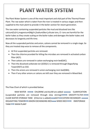
Now all the suspended particles and anion, cations cannot be removed in a single stage. So
they are treated step-wise to remove all the components.
At first suspended particles are removed.
Then the chlorine provided for killing the microbes are removed in activated carbon
filter (ACF).
Then cations are removed in cation exchanging resin bed(SAC).
Then the dissolved carbonate ion ((C03)2-) is removed through Degasifying
Tower(DGT) as CO2.
Then the anions are removed in anion exchanging resin bed(SBA).
Then if any other anions or cations are left over they are removed in Mixed Bed.
The Flow Chart of which is provided below:
RAW WATER CHLORINE and ALUM are added CLARIFICATION
(suspended particles are removed through slow stirring) GRAVITY FILTER
CLEAR WATER STORAGE TANK (Chlorine is added) ACF CATION EXCHANGER
DEGASIFYING TOWER ANION EXCHANGING BED MIXED BED DMSTORAGE
TANK MAIN PLANT
2.
3. REQUIREMENT AND UTLISATION OF WATER INSIDE
VARIOUS SECTIONS OF DVC (RTPS)
1. DM water is used to feed the boiler.
2. Cooling water is used to extract heat from the steam and hot water and transfer it to
the atmosphere.
3. Mixing of bottom ash with water to form slurry.
4. APH wash pump(Air-pre Heater wash pump)
5. Generator stator cooling (DM water).
6. Service Water
7. Rotor cooling is done by sealing the rotor by hydrogen which is extracted from water.
8. Lubricating oil cooling.
9. Bearing cooling.
VARIOUS STEPS TO PRODUCE DM WATER INSIDE RTPS:
RAW WATER RESERVIOR AND PUMP HOUSE:
The raw water from the Panchet Dam is stored in the raw water reservoir. The raw
water reservoir also serves as an aeration tank which helps to remove the bad smell of H2S
from the raw water. The pump house pumps the water from raw water reservoir and sends
it for various types of filtration.
Raw main water pump
4. CHEMICAL DOSING:
The raw water may contain suspended solids as large as 1000NTU in certain part of
the year. The chemical dosing system for the treatment of raw water has been done
by alum and chlorine dosing. By the addition of alum the suspended particles become
heavy and the have a better chance to settle down to the bottom.
By the addition of chlorine the microbes and the germs in the water are killed. Also a
little amount of chlorine in the water prevents the formation of algae in various
tanks.
CLARIFIER:
Clarifiers are settling tanks built with mechanical means of continuous removal of
solid being deposited by sedimentation. The water is stirred slowly by means of a
motor and the sludge gets deposited to the bottom of the tank. Clarifier is generally
used to remove solid suspended particulates or suspended solids from water for
clarification.
The sludge is then removed from the clarifier with the help of sludge disposal pump.
Clarifier Sludge Disposal pump
5. GRAVITY FILTER:
Closed rectangular and steel shell filled with layers of sand and gravels. It functions
with the pressure of the incoming water. Water passes through different layers of
sand where the total suspended particles in the water are removed.
During Back washing the GSF water is passed in reverse direction though the gravity
filter
The water from the gravity filter is stored in an underground gravity filter tank.
DM WATER PLANT:
After the water is stored in Gravity filter tank it is then pumped and brought into the
DM water plant. The filtered water brought into the DM water plant is again treated
in several steps inside the DM water plant.
ACTIVATED CARBON FILTER.
SAC- (Strongly Acidic Cation Exchanger).
DEGASIFYING TOWER.
SBA (Strongly Basic Anion Exchanger).
MIXED BED.
6. ACTIVATED CARBON FILTER (ACF):
The filtered water containing Chlorine ions is harmful for anion and cation
exchanging bed. So they should be removed before sending the water to the SAC and
SBA. Here the ACF serves as an agent to remove the chlorine from the chlorinated
water. There are many types of high-tech activated carbon filters present available
for industrial water filtration systems. Activated carbon can exhibit varying
performances characteristics depending upon the strata from which it is derived.
The process of activation opens up the carbon’s massive no of pores and further
drives off unwanted molecules. The open pores are what allow the carbon to capture
contaminants known as absorption.
Activated carbon may be used to remove chlorine with little degradation or damage
to the carbon. Dechlorination occurs rapidly and flow rates are typically high.
7. CATION EXCHANGING BED or SAC (Strongly Acidic Cation Exchanger):
After the water comes out of the ACF it enters into the SAC where the strong cations
like Ca2+,Mg2+,Na+,Al3+ are removed by matrix of resin which holds the cations by
the reacting with it. The matrix (R1 ) is Styrene and Vinyl Benzene Copolymer. The
reaction of which is provided below:
R1-SO3H + Na+ R1-SO3Na + H+
2R1-SO3H + Ca2+ R1-SO3-Ca-SO3R2 + 2H+
In this way it removes various cations from the filtered water.
The cation exchanging bed which is weakened during repeated use can easily
be regenerated with the use of 3% HCl.
After the cations are removed the water is sent to the Degasifying tower.
8. DEGASIFYING TOWER:
Degasifying tower is used to remove carbonate ions ((CO3)2-). The water falls down from
the top of the water and air is provided from the bottom of the tower through a pump. The
air oxidizes the carbonate ion in the water and the carbon di-oxide escapes out and the
water becomes free of carbonate ion. Then the degasified water goes to the DG sump.
Degasifying tower in RTPS DG tank in RTPS
Next the water goes to the anion exchanging bed.
9. ANION EXCHANGING BED or SBA (Strongly Basic Anion Exchanger):
After the water coming out of the degasifying tower it enters the anion exchanging bed
where all the anions like Chloride ion (Cl-), Sulphate ion ((SO4)2-) etc. are removed. The
resin matrix containing the styrene vinyl benzene along with (NH4)OH reacts with the water
containing anion and holds the anion with it leaving the OH- ion. Reaction of which is
shown below:
R2-NH4OH + Cl- R2(NH4+)Cl- + OH-
2R2-NH4OH + (SO4)2- 2R2(NH4)SO4 + 2OH-
The anion exchanging bed destroyed after the repeated use can easily be regenerated by
the use of 5% caustic soda.
The water is then sent to the mixed bed.
10. MIXED BED:
Mixed Bed is an equi-molar mixture of both cation and anion exchanging resin bed. If any
cation or anion escapes from the previous cation or anion exchanging bed, then that cation
or anion are absorbed in this mixed bed. This is present at the end of the DM plant. After
this the Demineralized water is pumped to the DM water storage tank. Almost all the ions
are absorbed in the previous ion exchanging bed, only a few get absorbed in the mixed bed.
The H+ and OH- left over reacts with each other and forms pure DM water. The water
coming out of this section possess a PH almost equal to 7, conductivity equal to 0.1,
suspended silica equal to 1-5 ppb.
DM PUMP HOUSE:
DM pump house pumps out the water from the DM plant and sends it to the DM water
storage tank. There are three sets of pumps in the pump house which pumps from the
three parallel sections of the DM plant and sends it to the separate DM water storage tank.
DM water storage stores the water and the water is sent to the main plant.
11. DM water pump house in RTPS
DM water storage tank in RTPS
13. Here at first the Bus bar comes from the 11 KV Switchboard of the switchgear room. It
enters through two incomers and between these two incomers there is a bus coupler. Now
this 11 KV is stepped down to 3.3 KV with an oil type transformer. In this way the HT
switchgear room (3.3KV) gets charged and power goes there by two incomers and a bus
coupler is present between them. In each incomer there is one bus PT and one line PT for
protection purpose which is connected to the relay.
HT SWITCHGEAR ROOM IN RTPS
Now another section carries current to the 415V LT switchgear room. A dry type
transformer steps down the voltage from 11KV to 415V.The rating of which is provided
below in the image. Here also the current enters through two incomers. And one bus
coupler is present between them. Other lines are also there which carry the power to the
raw water pump, DM MCC by stepping down the voltage from 11kv to 415V.