
Empfohlen
Weitere ähnliche Inhalte
Was ist angesagt?
Was ist angesagt? (20)
Ähnlich wie BCON PROJ 1
Ähnlich wie BCON PROJ 1 (20)
Mehr von Atiqah Ghazali
Mehr von Atiqah Ghazali (19)
Kürzlich hochgeladen
Kürzlich hochgeladen (20)
BCON PROJ 1
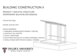
- 1. BUILDING CONSTRUCTION II PROJECT 1: SKELETAL STRUCTURE (TEMPORARY BUS SHELTER DESIGN) GROUP MEMBERS: 1. HABEEBAH ZAINAB SAYED HOSSEN | 0327492 2. HOR XEUT YIN | 0327770 3. JIJI NG | 0904Y72861 4. NUR FARAHIYAH BILLAH HJ MOHD ASMADEE | 0324416 5. NURUL ATIQAH BINTI MOHD GHAZALI | 0325630 TUTOR: MR. RIZAL INTAKE: AUGUST 2017
- 2. CONTENTS: 1. INTRODUCTION..............................................................1 2. DESIGN CONCEPT.......................................................1 3. MASSING.............................................................................2 4. DESIGN CONSIDERATION.....................................3-4 5. DESIGN DEVELOPMENT.........................................5 6. FINAL DESIGN (DRAWINGS)................................6-8 7. SPECIFICATIONS...........................................................9 8. MATERIAL ANALYSIS.................................................10-11 9. JOINTS...................................................................................12 10. CONSTRUCTION PROGRESS............................13-15 11. LOADS AND FORCES ..............................................16-17 12. FINAL PHOTOS OF MODEL.................................18 13. REFERENCES.................................................................19
- 3. INTRODUCTION DESIGN CONCEPT A bus stop is a designated place where buses stop for passengers to board or alight from a bus. Our design aims to use the least material and screws to highlight on the portability and easy installation throughout the construction process. Materials used are extremely light weight and removable joints are applied on the design. 1 This project aims for us to understand the skeletal structure and its structural components. We have to understand how a skeletal structure reacts under loading. We have to analyze the issue of strength, stiffness and stability of structures includes modes of structural systems, forces, stress and strain and was of static. So, in a group of 5, we have to design a bus shelter, a temporary one, and create a 1:5 model. We must clearly show the building components: roof, column, walls, and floor.
- 4. MASSING 2 The general massing of our temporary bus shelter is based on two forms; right-angle triangular prism which rests above cuboid. Cuboid has large surface area in contact with ground and the overall horizontality of both cuboid and right- angle triangular prism lower the center of gravity which make the bus shelter stable and able to accommodate.
- 5. DESIGN CONSIDERATIONS 3 ACCESS SHELTERSPACIOUS CAPACITY Able to accommodate 5- 6 passengers. It provides easy access to go in and out from the shelter. Protects the waiting passengers from weather ( i.e. rain).
- 6. DESIGN CONSIDERATIONS (cont.) 4 BENCHES Benches facing the street. The structure and material chosen for strength and durability. Provide openings and transparency so that natural light will be use more. LIGHTING Provide semi- transparency enclosure so that the bus drivers are able to see inside. Also the passengers will know when the bus has arrive due to no blockage TRANSPARENCY
- 7. DESIGN DEVELOPMENT STAGE 1 We have decided to use cube and prism to be the form of our design. STAGE 4 ( FINAL) STAGE 3 STAGE 2 We have come out with a rough sketch of how the design is going to look like. There is two rows of seats and the back seat is higher than the one in front. It is something like a staircase seating area. What to change: - Seating: not convenient to get to the seat at the back - Knee brace to be removed because there is enough support There is just a row of seat one so it will be wider to accommodate 5-6 people. We are now at the stage discussing the detail part of the design (joints, dimension, etc.) What to change: - Material: from steel to timber, it is easier to construct as there is less bolts and nuts - Roof: become a whole slanted structure to make construction easier The whole design has been finalised. 5
- 8. FINAL DESIGN ( DRAWINGS) 6 ROOF PLAN FLOOR PLAN 3,000 mm 3,000 mm 2,000mm 2,000mm
- 9. FINAL DESIGN ( DRAWINGS) 7 FRONT ELEVATION 3,000mm 2,750mm
- 10. FINAL DESIGN ( DRAWINGS) 8 RIGHT ELEVATION LEFT ELEVATION 2,750mm 2,500mm 2,000 mm 1,000 mm 1,000 mm
- 11. SPECIFICATIONS 9 HOLLOW STEEL SECTION: 90 mm x 90 mm 90 mm 90 mm LAMINATED TIMBER FLOOR COVER: 2,000 mm x 3,000 mm Thickness: 75 mm TIMBER COLUMN: 150 mm x 150 mm 150 mm 150 mm 3,000 mm 2,000 mm LAMINATED TIMBER BENCH: 300 mm x 3,000 mm Thickness: 50 mm 3,000 mm 300 mm TIMBER BEAM: 50 mm x 100 mm TIMBER ROOF RAFTERS: 50 mm x 100 mm Length: 2,000 mm POLYCARBONATED ROOF: 3,000 mm 2,000 mm 50 mm 100 mm 100 mm 50 mm ISOMETRIC VIEW
- 12. MATERIAL ANALYSIS 10 Hollow Steel Section ( Floor beam structure) Glued Laminated Timber ( Floor cover and bench) Glued laminated timbers (glulam) are manufactured by end joining individual pieces of dimension lumber or boards together with structural adhesives to create long-length laminations. These long-length laminations are then face boned together with adhesives to create the desired glulam shape. Commonly used as beams. The section’s inherent flat surfaces makes it more economical for joining and other fabrication processes. It possessed clean lines, it is functional, and interacts less with external environmental effects. In construction, hollow steel sections create lightweight and visually attractive structures that benefit communities and environments.
- 13. MATERIAL ANALYSIS (cont.) 11 Polycarbonate (Roof) Timber ( Columns, beams and roof rafters) Polycarbonate is a durable material. Although it has high impact-resistance, it has low scratch-resistance. It also has a high heat deflection temperature and absorbs very little moisture. Its strength, impact resistance and transparency (unfilled grades only) also make it an ideal material for certain transparent structural applications. Timber can be easily connected using nails, screws, bolts, connectors. It is lightweight and easy to handle in manufacture, transport and construction. It has a good durability characteristics and good insulating properties against heat. Concrete is for the foundation part of the shelter. It has relatively high of compressive strength, able to withstand loads from the shelter. It goes to a process of formwork to form a rectangular shape concrete block that is distributed evenly on all sides of the shelter.. Concrete ( Foundation)
- 14. JOINTS 12 Mortise and Tenon Joint / End Bridle Joint End bridle joint (also known as open slot mortise and tenon) is the method of joining timber by working a solid rectangular projection in the one piece and cutting a corresponding cavity to receive it in the adjoining piece. The projection is called the tenon, and the cavity the mortise. It joins two members at their respective ends, forming a corner. This form of joint is commonly used to house a rail in uprights, such as legs. It provides good strength in compression and is fairly resistant to stacking, although a mechanical fastener or pin is often required. Mortise Tenon DETAIL DIAGRAM OF JOINING COLUMN AND BEAM TOGETHER Column (Mortise)Beam (Tenon)
- 15. CONSTRUCTION PROGRESS 13 1. Cut a section at the top of the columns. Dimension of cut: 50 mm x 100 mm x 150 mm. 2. Screw the column on to the floor cover 3. Slot in the timber beam into the cut section of the column 50 mm 150 mm 100 mm 4. Place the roof rafter on top of the column and beams.
- 16. CONSTRUCTION PROGRESS (cont.) 14 5. Place the rest of the rafters on top of the column and beams. 6. Screw the roof polycarbonated cover on top of the rafters/ 7. Screw the welded hollow beam structure on the bottom of the timber flooring.
- 17. CONSTRUCTION PROGRESS (cont.) 15 8. Mark the position of the L Bracket for the seating and screw on the column at the back.
- 18. LOADS AND FORCES 16 The columns, which is the compression member, transfer the load above it equally to the foundation. Column Rafter Roof Beam The roof is supported by the rafters and both of them are supported by roof beam. Transferred load from the roof Distributed load from roof beam to column Transferred load to foundation through columns The load is transferred from the roof to the rafters, which is then distributed to the roof beam and will be transferred through columns to the foundation.
- 19. LOADS AND FORCES (cont.) 17 The bottles of water represent loads from heavy rain. The bus shelter is able to withstand the load as it is supported by 5 columns within an area of 2m by 3m. The number of columns is sufficient to withstand heavy load within the area. The load will be transferred from roof to the rafters and distributed equally to the columns through the roof beam, then it will finally be transferred to the foundation through columns. WEIGHT OF BOTTLES LOAD ( RAIN) : 7.5 kg
- 20. PHOTOS OF FINAL MODEL 18 Base with hollow beams Roof Cover Back ElevationFront Elevation Right Elevation Left Elevation
- 21. REFERENCES 19 APA. (2008). Gulam Design Specification. Retrieved on Oct. 12, 2017 from http://www.drjlumber.com/wp- content/uploads/2014/07/Glulam-design-specs.pdf APTA. (2010). Bus Stop Design and Placement Security Considerations. Retrieved on Oct. 12, 2017 from http://www.apta.com/resources/standards/Documents/APTA-SS-SIS-RP-008-10.pdf Boedeker. (2017). Polycarbonate Specifications. Retrieved on Oct. 12, 2017 from http://www.boedeker.com/polyc_p.htm Glulam. (2014). More About Glulam. Retrieved on Oct. 12, 2017 from http://www.glulam.co.uk/about_designData.htm STA. (2014). Timber as a structural material – an introduction. Retrieved on Oct. 12, 2017 from http://www.cti- timber.org/sites/default/files/STA_Timber_as_structural_material.pdf TATA. (2013). Hollow Sections. Retrieved on Oct. 12, 2017 form https://www.tatasteeleurope.com/file_source/StaticFiles/Business_Units/Corus_Tubes/Tubes/TST01_Overview_Bro chure_NH_update.pdf