3. • WBSETCL
• About the substation
• Bay arrangement
• Single line diagram
• Receiving power
• Step down of voltage
• Sending power
• Phase to phase double channel system
• Various frequencies of nearby substations
1
2
4
13
15
Contents
4. Introduction
West Bengal State
Electricity Transmission
Company Limited
(WBSETCL) was set up
in 2007 following the
unbundling of the state
electricity board of
West Bengal.
WBSETCL is the
eleventh largest of the
23 state transmission
utilities in the country.
It is responsible for
power transmission
across the state at the
400 kV, 220 kV, 132 kV
and 66 kV Voltage
levels. The company
also manages the state
load dispatch centre,
which monitors and
controls the grid
operations.
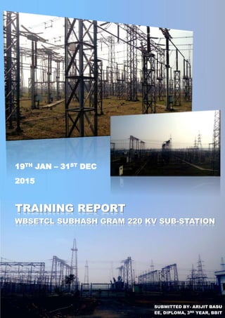
The Subhash Gram 220 KV Substation under West Bengal
State Electricity Transmission Company Limited (WBSETCL)
is situated 3 KM away from Subhasgram Railway station.
Its commissioning date is 18th August 2009. This
Substation is stretched over 22.59 acres. This substation
mainly gets power from the nearby 400 KV Substation of
Power Grid Corporation of India Limited (PGCIL).
It receives power at 220 KV voltage level from the nearby
440 KV PGCIL Substation and feeds it to
Lakshmikantapur1, Lakshmikantapur2, Kasba, and KLC 220
KV Substation. Then the 220 KV supply is stepped down to
132 KV and feeds to Kasba1, Kasba2, Joka and Sonarpur
132 KV feeder. Then the 132 KV supply is stepped down to
33KV and feeds to Madarhat and Baruipur. After that, the
33 KV is stepped down to 0.4 KV and supplied for auxiliary
station service.
The Substation is well equipped with modern devices. It
has two 220/132KV 160 MVA Power transformers, two
132/33KV 31.5 MVA Power transformers, two 33/0.4KV 630
KVA Station Service transformers and two 33/0.4KV
100KVA Earthing cum Station Service transformers. And
also it has many Current Transformers (CT), Potential
Transformers (PT), Capacitor Voltage Transformers (CVT),
Wave Trap, Lightning Arrester, Central Break Isolators,
Pantograph Isolators and a lot of safety equipment.
Subhash Gram 220 KV substation
Training report
Page 1
5. Substation layout
Subhash Gram 220 KV sub-station has three switchyards
based on the three different voltage voltage levels.
Training report
Page 2
220 KV BAYS
•220 KV PGCIL-1
•220 KV PGCIL-2
•220 KV Kasba
•220 KV KLC
•220 KV
Lakshmikantpur
Feeder-1
•220 KV
Lakshmikantpur
Feeder-2
•220 KV bus coupler
•220 KV transfer bus
coupler
•220 KV side of 160
MVA 220/132/33 KV
TRF-1
•220 KV side of 160
MVA 220/132/33 KV
TRF-2
132 KV BAYS
•132 KV side of 160
MVA 220/132/33 KV
TRF-1
•132 KV side of 160
MVA 220/132/33 KV
TRF-2
•132 KV side of 31.5
MVA 132/33 KV TRF-
3
•132 KV side of 31.5
MVA 132/33 KV TRF-
4
•132 KV Joka feeder
•132 KV Kasba
feeder-1
•132 KV Kasba
feeder-2
•132 KV Sonarpur
feeder
•Transfer bus coupler
33 KV BAYS
•33 KV side of 31.5
MVA 132/33 KV TRF-
3
•33 KV side of 31.5
MVA 132/33 KV TRF-
4
•Transfer bus coupler
•33 KV feeder-1
•33 KV feeder-2
•33 KV feeder-3
•33 KV feeder-4
•33 KV feeder-5
•33 KV feeder-6
Every equipment in the substation are well earthed. There is a large sheet made of
metal conductor net bedded under the ground connected with every earth conductors
of substation equipment. It is further connected with a low resistance metal plate
(earth plate) which is buried about 70 Ft. deep into the ground.
7. Operation
Training report
Page 4
Receive
power
Step down
voltage
Send
power
Power is received in the substation through 2
PGCIL (Power Grid Corporation of India Limited)
feeders. The receiving end voltage is 220 KV.
Before they come in contact with other equipment,
the three phases has to pass through lightning
arresters.
Lightning arresters are protecting devices. It
protects the substation equipment from over
voltage or surges in transmission lines.
The typical lightning arrester has a high-voltage
terminal and a ground terminal. When a lightning
surge (or switching surge, which is very similar)
travels along the power line to the arrester, the
current from the surge is diverted through the
arrestor, in most cases to earth.
After passing through the lightning arrester, one
of the 3 phases passes through CVT i.e. Common
Voltage Transformers.
A capacitor voltage transformer (CVT) is a
transformer used in power systems to step-down
extra high voltage signals and provide low voltage
signals either for measurement or to operate a
protective relay. In its most basic form the device
consists of three parts: two capacitors across which
the voltage signal is split, an inductive element
used to tune the device to the supply frequency
and a transformer used to isolate and further step-
down the voltage for the instrumentation or
protective relay. The device has at least four
terminals, a high-voltage terminal for connection
to the high voltage signal, a ground terminal andLightning arrester
8. Training report
Page 5
at least one set of secondary terminals for
connection to the instrumentation or protective
relay. CVTs are typically single-phase devices used
for measuring voltages in excess of one hundred
kilovolts where the use of voltage transformers
would be uneconomical. In practice the first
capacitor, C1, is often replaced by a stack of
capacitors connected in series. This results in a
large voltage drop across the stack of capacitors
that replaced the first capacitor and a
comparatively small voltage drop across the
second capacitor, C2, and hence the secondary
terminals.
Capacitor Voltage Transformer
In Subhash Gram substation, the CVTs are
connected with each blue phases of every R-Y-B
lines.
CVTs also help receivers to receive high frequency
signals that are for communication purpose.
The remaining high frequency signals in the
feeders are filtered by wave traps.
Wave trap or line trap is basically a low pass filter
circuit used in substations.
The function of this trap is to trap the unwanted
waves (high frequency communication signals). It
is connected to the main incoming feeder so that
it can trap the waves which may be dangerous to
the instruments here in the substation.
After that, the feeder passes through current
transformers.
Wave trap
Current transformers are basically step up
transformers basically used to steps down the
current from 1600 or 800 amps to 1 amp so that it
can be measured using sensitive low rating
devices.
The main use of this transformer is
a. Distance Protection
b. Backup Protection
c. Measurement
There are 2 types of current transformers in the
substation. One is live tank and the other is dead
tank. In the live tank transformer, the tank is
directly connected with the feeder, while in the
dead tank type, the tank is insulated from the
feeder and connected to earth conductor.
And according to turns ratio also, there are two
types of CTs. One is of 1600:1 rating and the other
is of 800:1 rating.
After current transformers, the feeders ends at the
isolators.
Isolators isolate the feeders from the main bus.
The main difference between circuit breaker and
isolator is that circuit breaker is that circuit breaker
can make or break a circuit but isolator is to be
used only when the circuit is already open. It
cannot break a closed circuit.
There are two different types of isolators used in
the substation.
a. Pantograph Isolator or Jumper
b. Centre Break Isolator
ClosedOpen
Pantograph isolator
Current Transformer (live tank)
9. Training report
Page 6
All 3 buses i.e. main bus-1, main bus-2 and transfer
bus are separated from each other by these
isolators.
It is to be remembered that, before operating the
isolators, we should ensure that the circuit is open.
If not, then we first have to break the circuit using
circuit breakers then operate the isolators.
Circuit breakers are used to make or break the
circuit in high voltage lines.
Circuit breakers are also used for protection
purposes. Whenever they sense any dangerous
over current, over voltage, earth leakage etc. faults,
they break the circuit immediately. They can be
operated remotely from the control room. The
insulation used in the circuit breaker should be
very high in terms to avoid breakdown of the
medium. This is why the circuit breakers used in
the Subhash Gram substation are gas insulated
(SF6). They provide better reliability than oil
Open
Closed
Centre break isolator
There are 2 main bus and a transfer bus in the 220
KV side. Each main bus is designed to take the full
load without any fault.
Bus bar with isolators
Centre break isolator
Although, for operational efficiency related issues,
both bus bars are kept energised.
The isolators are generally operated with 3 phase
induction motors that can be controlled either
individually or in gang operation mode. They can
also be operated remotely from the control room.
insulated CBs. The best insulation property can be
provided by vacuum circuit breakers. But they are
very expensive and also difficult to maintain.
The interrupting chamber has been designed in
such a way as to increase the mechanical
resistance of the working part and take advantage
of the low wear rate of the contacts subjected to
the arc in SF6. The working part is enclosed,
providing insulation between the circuit - breaker
input and output.
10. Training report
Page 7
After the bus bars are energised, the electrical power is carried from the bus bars to a combination of two 160
MVA 220/132/33 KV transformers connected in parallel with the bus bars. The transformers step down the voltage
from 220 KV to 132 KV and 33 KV.
A transformer is a device that transfers electrical energy from one circuit to
another through inductively coupled conductors—the transformer's coils. A
varying current in the first or primary winding creates a varying magnetic flux in
the transformer's core and thus a varying magnetic field through the secondary
winding. This varying magnetic field induces a varying electromotive force (EMF),
or "voltage", in the secondary winding. This effect is called inductive coupling.
160 MVA Transformer
The technique used in the design and construction
of high voltage transformer varies from
manufacturer. The active part of transformer
consists of core & winding. Other parts are- tank &
cover, conservator, cooling accessories, etc.
Core is a manufactured form lamination of Cold
Rolled Grain Oriented Silicon Steel, which gives
very low specific loss at operating flux, is always in
the direction of grain oriented. The core clamping
structure is designed such that it takes care of all
the forces produced in the winding in the event of
any short circuit.
Winding are made from paper insulated copper
conductors which are transposed at regular
intervals throughout the winding for ensuring
equal flux linkage and current distribution
between stands. Interleaved or shielded.
construction adopted for high voltage winding to
ensure uniform distribution of impulse voltage
insulating spacers in the winding are arranged
such that oil is directed through the entire winding
for ensuring proper cooling.
Tank and cover are manufactured by welding steel
plates and are suitable for withstanding full
vacuum and positive pressure test as per CBIP
manual. for large capacity power transformers ,the
tank will be of bell type construction .this is to
avoid lifting of heavy core and winding ,which are
requires very large capacity crane at site .the
weight of upper tank will be much less in
comparison with that of core & winding and can
be lifted by using a small capacity crane.
11. Training report
Page 8
Conservator function is to maintain the required
transformer oil level in the main tank and OLTC
above transformer internal accessories, allowing
oil expansion and construction during
temperature changes with breather, for installation
of buchholz relay and gas collection and MOLG
installation.
The transformers are provided
with various cooling systems.
For ONAN/ONAF cooling, oil
flows through the winding
external cooler unit attached
to the tank by thermo-
symphonic effect.
For AF/OD, AF/OF WF cooling,
the oil is directed through the
winding by oil pumps
provided in the external cooler
unit.
External cooler unit/units
consists of pressed steel sheet
radiators mounted directly on
the tank or separate cooler
banks for air-cooled
transformer and oil to water
heat exchanges for water
cooled transformers.
A Dehydrating Breather is
used to dry the air that
enters a transformer as
the volume of oil
decreases because of fall
in temperature. They are
to be replaced with a new
one when the blue colour
turns into pink.
Conservator with air cell
Flexible Separation is fitted inside the cylindrical
conservator. Oil being outside the separator is in
direct contact with atmosphere.
Each valve should
be cleaned from
inside with
compressed air jet.
All particles should
be removed from
tank side..
It pumps the oil into the
tank.
Consider the case of furnace
Transformer in which one flow
indicator can be mounted on
suitable member of oil circulating
pipe of heat changer. It can be used
on liquid circulating pipes in
chemical process.
It indicates the oil level in the tank.
It is mounted on the oil tank with
nut bolts. Several indicators are
mounted in series for high capacity
tanks.
The temperature indicator is
used as an oil temperature
indicator or as winding
temperature indicator for the
protection of liquid
immersed power
transformer.
Exhaust type cooling
fans used on
Transformer are
designed to operate
outdoors in all
weather conditions.
12. Training report
Page 9
The parallel operation of transformers is common in any industry. This mode of
operation is frequently required. When operating two or more transformers in
parallel, their satisfactory performance requires that they have:
1. The same voltage-ratio
2. The same per-unit (or percentage) impedance
3. The same polarity
4. The same phase-sequence and zero relative phase-displacement
Out of these conditions 3 and 4 are absolutely essential and condition 1 must be
satisfied to a close degree. There is more latitude with condition 2, but the more
nearly it is true, the better will be the load-division between the several
transformers.
This loss occurs due to electrostatic stress reversals
in the insulation. It is roughly proportional to
developed high voltage and the type and
thickness of insulation. It varies with frequency. It is
negligibly small and is roughly constant. (Generally
ignored in medium voltage transformers while
computing efficiency).
A sizeable contribution to no-load losses comes
from hysteresis losses. Hysteresis losses originate
from the molecular magnetic domains in the core
laminations, resisting being magnetized and
demagnetized by the alternating magnetic field.
Each time the magnetising force produced by the
primary of a transformer changes because of the
applied ac voltage, the domains realign them in
the direction of the force. The energy to
accomplish this realignment of the magnetic
domains comes from the input power and is not
transferred to the secondary winding. It is
therefore a loss. Because various types of core
materials have different magnetizing abilities, the
selection of core material is an important factor in
reducing core losses. Hysteresis is a part of core
loss. This depends upon the area of the
magnetising B-H loop and frequency.
The losses in a transformer are as under.
1. Dielectric Loss
2. Hysteresis Losses in the Core
3. Eddy current losses in the Core
4. Resistive Losses in the winding conductors
5. Increased resistive losses due to Eddy Current Losses in conductors.
6. For oil immersed transformers, extra eddy current losses in the tank structure.
The alternating flux induces an EMF in the bulk of
the core proportional to flux density and
frequency. The resulting circulating current
depends inversely upon the resistivity of the
material and directly upon the thickness of the
core. The losses per unit mass of core material,
thus vary with square of the flux density, frequency
and thickness of the core laminations.
By using a laminated core, (thin sheets of silicon
steel instead of a solid core) the path of the eddy
current is broken up without increasing the
reluctance of the magnetic circuit. For reducing
eddy losses, higher resistivity core material and
thinner (Typical thickness of laminations is 0.35
mm) lamination of core are employed. This loss
decreases very slightly with increase in
temperature. This variation is very small and is
neglected for all practical purposes. Eddy losses
contribute to about 50% of the core losses.B-H curve (hysteresis loop)
13. Training report
Page 10
These represent the main component of the load
dependent or the variable losses, designated as
I2R or copper losses. They vary as square of the
r.m.s current in the windings and directly with D.C.
resistance of winding. The resistance in turn varies
with the resistivity, the conductor dimensions; and
the temperature.
R = ρ(l/A)
Where,
R = Winding resistance, Ω
ρ = Resistivity in Ohms - mm2/m.
l = Length of conductor in metres
A = Area of cross section of the conductor, mm2
In addition, these losses vary with winding
temperature and thus will vary with the extent of
loading and method of cooling.
Conductors in transformer windings are subjected
to alternating leakage fluxes created by winding
currents. Leakage flux paths, which pass through
the cross section of the conductor, induce
voltages, which vary over the cross section. These
varying linkages are due to self-linkage as also due
to proximity of adjacent current carrying
conductors. These induced voltages, create
circulating currents within the conductor causing
additional losses. These losses are varying as the
square of the frequency.
For an isolated conductor in space, the varying
self-linkage over the section, leads to clustering of
the current near the conductor periphery. This is
known as Skin Effect. The same effect, with the
addition of flux from surrounding conductors,
(Proximity effect) leads to extra losses in thick
conductors for transformer windings. These losses
are termed as Eddy Current Losses in conductors.
The Test Certificate mentions the load losses,
which include these eddy losses in conductors at
supply frequency (50 Hertz) as also the eddy losses
in tank structure in general at the same frequency
in the case of oil cooled transformers. For dry type
transformers, tank losses are absent.
The contribution of eddy losses including tank
losses, over the basic copper losses for an
equivalent D.C. current, can be estimated from the
difference in measured load losses and expected
copper losses at the test current at the test
temperature. For normal designs it ranges from
5% to 15%. Detailed subdivision is available only
from design data. It can be taken as 10% of load
losses in the absence of specific design data. These
extra losses vary with square of frequency and
square of per unit harmonic current.
The eddy losses in the tank structure are
equivalent to the dissipation in a loaded secondary
with leakage reactance. The variation is not as the
square of frequency, and it is customary to take a
value of 0.8 for the exponent.
The Eddy losses in a thick conductor can be
reduced by decreasing the radial thickness by
sectionalising the conductors (multi-stranded) and
increasing the axial dimension. The sectionalised
conductor has to be transposed to make it occupy
all possible positions to equalise the e.m.fs to the
extent possible.
It is important to transpose each layer so that each
layer is connected in series with a path in each one
of the possible N positions before being
paralleled. Thus circulating current is forced to
flow in a relatively very thin conductor..
Some leakage flux invariably goes in air paths
away from the transformer. Strength of this stray
flux diminishes and varies inversely with distance.
If it links with any conducting material, it will
produce eddy losses in that material. For oil
immersed transformers, some stray flux links with
some parts of the tank and causes extra eddy
current losses in the structure. These losses are
absent in dry type transformers.
Similarly, extra flux due to outgoing L.T.
conductors carrying large currents cause extra
eddy current losses in the structural portion
surrounding the leads.
Both these losses vary with frequency 0.8 , as
stated earlier.
The above discussion on transformer losses is
given only to gain familiarity with the fundamental
principles. The most important losses are core loss
and copper loss. The other losses are described
mainly to give a complete picture on losses.
16. Communication
Training report
Page 13
In Subhash Gram substation, phase to phase double channel circuit is used to have a backup option. If by
accident, one channel is broken, communication can still be done through the other channel.
After the signals are received by LMDU and LMU, they are sent to the PLCC room through
underground or surface cables.
LMDU LMU
PLCC
room
Wave trap Wave trap
CVT CVT
Line Matching
Double Unit
Line Matching Unit
Phase to phase double channel system
Phase Phase
After the voltage is stepped down, the energy is carried to the 132 KV and 33 KV bus bars through feeders. Out
going arrangement of the substation is the same but reversed as the incoming arrangement. The outgoing power
has to pass all the various stages, that it had to face while incoming, but in reversed sequence.
17. Training report
Page 14
In Subhasgram Substation, the communication system is very good. There is a
walkie talkie of very high frequency (VHF), which works with the help of a 12V DC
charger. This walkie talkie is use to contact with Madarhat, Sonarpur and other
nearby Substations. And also it is used to contact with yard with control room and
to give the information to the control room about any fault observed at line
patrolling time. The frequency of this Substation is 157.125. Wherever there is a
machine of this frequency, it can contact with this Substation.
There is another machine called PLCC (Power Line Career Communication). This
machine is used to contact with the feeders. The carriers to the power line
connection have been taken from co-axial cable. This PLCC is a combination of
four lines.
EPAX is a direct communication line between Subhash Gram 220 Substation,
PGCIL, and the other three lines, KASBA, LAKHSMIKANTAPUR and KLC. These
three lines operate through dialling via EPAX (Electronics Private Automatic
Exchange) carrier through power line (works directly or through charger at 48
Volt DC). And, besides those there is a telephone, which is used for emergency
contacts.Inside EPAX device
Each nearby substation has their unique frequency levels at which
communication for different purposes are done.
Tx 195.57 KHz
Rx 191.57 KHz
Tx 207.57 KHz
Rx 203.57 KHz
Ch.1 Tx 223.57 KHz
Rx 215.57 KHz
Ch.2 Tx 227.57 KHz
Rx 219.57 KHz
Tx 143.57 KHz
Rx 147.57 KHz
Tx 135.57 KHz
Rx 139.57 KHz
Ch.1 Tx 151.57 KHz
Rx 159.57 KHz
Ch.2 Tx 155.57 KHz
Rx 163.57 KHz
Tx 183.57 KHz
Rx 187.57 KHz
Tx 107.57 KHz
Rx 111.57 KHz
Ch.1 Tx 119.57 KHz
Rx 127.57 KHz
Ch.2 Tx 123.57 KHz
Rx 131.57 KHz
18. Conclusion
Training report
Though the period of 19th January to 31st January
(except holidays) was not enough to learn everything in
the substation, still I believe that, the knowledge &
inspiration I gained and things I learned in the guidance
of highly skilled professionals in Subhash Gram 220 KV
substation will help me becoming a dedicated and
skilled electrical engineer in future.
Page 15
Subhash gram 220 KV substation is an ideal substation equipped with all modern machines
and equipments. They are observed, tested and maintained in a regular basis. Safety is given a
huge importance in the substation. There are fire fighting tools in every floor of the office
and also all around the switchyard. There are safety and precaution related attractive posters
stuck on the walls inside the office and control room. The switchyard and premises are nicely
cleaned. The security personnel are very nice and friendly. The divisional and assistant
engineers, working in the substation are highly talented professionals and also nice as a
person. They helped us learning and understanding how things work in details and also
cleared all of our doubts one by one with great interest and motivated us to try our best to
become successful engineers.
Flowers of the garden of Subhash Gram 220 KV substation