
Empfohlen
Empfohlen
Weitere ähnliche Inhalte
Was ist angesagt?
Was ist angesagt? (20)
Ähnlich wie Case study on Leadenhall Building KUET BECM 2k15
Ähnlich wie Case study on Leadenhall Building KUET BECM 2k15 (20)
Kürzlich hochgeladen
Kürzlich hochgeladen (20)
Case study on Leadenhall Building KUET BECM 2k15
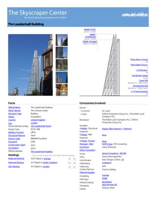
- 1. Facts The Leadenhall Building The Cheese Grater Building Completed United Kingdom London 122 Leadenhall Street EC3V 4AB office steel BREEAM Excellent 2001 2011 2014 The Leadenhall Building Official Name Other Names Structure Type Status Country City Street Address &Map Postal Code Building Function Structural Material Energy Label Proposed Construction Start Completion Official Website Rankings Regional Ranking Click arrows toview thenext taller/shorterbuildings #29 Tallest in Europe National Ranking #4 Tallest in United Kingdom City Ranking #4 Tallest in London CompaniesInvolved Owner • Current • Past Developer CC Land Oxford Properties Group Inc.; The British Land Company PLC The British Land Company PLC; Oxford Properties Group Inc. Rogers Stirk Harbour + Partners Arup Arup WSPGroup; M3 Consulting Laing O'Rourke alinea Consulting; AECOM Exova Warringtonfire Edco Design London W ordsearch DP9 Francis Golding Architect •Design Structural Engineer •Design MEP Engineer •Design Project Manager Main Contractor OtherConsultant •Cost •Fire •Landscape •Marketing •Planning •Urban Planner MaterialSupplier •Cladding •Elevator •Paint/Coating •Sealants •Steel Yuanda KONE AkzoNobel Sika Services AG Watson Steel TheLeadenhallBuilding Height:ToTip 224m / 735 ft Height: Architectural 224m / 735 ft Height:Occupied 202.9m / 666 ft Floors Above Ground 52 Floors Below Ground 4 #of Elevators 26 TopElevator Speed 8m/s TowerGFA 84,424m² / 908,732ft² DevelopmentGFA 84,424m² / 908,732ft² # of ParkingSpaces 22
- 2. The vision of this office tower is to preserve the view corridor to St. Paul’s along Leadenhall St. As a result, the tower slopes away from this view corridor, toward the north. The north elevation forms the backbone of the tower by providing all services, elevator access, and structural stability. Complete sections of this megaframe were manufactured in factories, including the steel, HVAC equipment and precast concrete floor slabs. All steel was custom-fabricated, and fire-coated with intumescent paint at the factory. The coloured toilets (blue for men, red for women) inserted into areas of the north core not occupied by lifts constituted “an architectural language of supergraphics” for that façade, given further expression by the orange and green frames of the glass lift cars and the yellow of their shafts. Building Introduction
- 4. Plans and Sections Vertical Section
- 5. From a structural perspective, the building is unusual for a building of its height. There is no central core; instead, the building makes use of a “tube” structural perimeter envelope, with an external support core, that allows for open floor plates. In addition, 85% of the building’s construction value consisted of prefabricated and off-site construction elements. The Leadenhall Building comprises a tapering, perimeter-braced diagrid structure containing the office floors and adjoins a northern support core, which houses all passenger and goods lifts, service risers, on-floor plant, and lavatories. Office floors are connected to the structural tube, termed the “mega- frame,” at every floor, without the need for further perimeter columns. Structural System
- 6. Structural System The structure aims to reinforce the geometry defined by the development envelope, which in turn creates the distinctive tapering form, and takes the form of a perimeter braced ‘tube’ that defines the extent of the floor plates. The ladder frame contributes to the vertical emphasis of the building, and encloses the fire- fighting cores. The frame also visually anchors the building to the ground. In its concept, the structure was to have no central concrete core, with an external steel frame and central steel core providing lateral stability and 26 passenger lifts at its northern core. This presented numerous challenges through the construction phase, which from 2011 to 2014 preoccupied architects and engineers for Sherwin-Williams, the supplier of coatings for fire and corrosion protection.
- 8. Complete M&E fit of the Leadenhall building in partnership with Ruddy Fit-Out. The main plant is situated within the basement and attic levels, which includes central chilled water plant and fully packaged cooling towers, HV standby generation consisting of four sets situated at levels 47 and 48 and boilers c/w gas booster sets. The programme was reduced as the high level on floor service installation and services within the risers were then fully modularised and delivered and installed with the steel frame of the building. On-floor plantrooms were completed and tested offsite prior to delivery, then dropped into position for module connection. Electrical and Mechanical System
- 9. Three Stokvis 1.5MW boilers fitted with Riello modulating burners have been supplied to The Leadenhall Building in the City of London to provide space heating throughout the building. Plant rooms are located above the offices from levels 46 to 52. The closed cell structure and high water vapoour resistance factor of Armaflex serves to prevent moisture ingress, whilst the low thermal conductivity value stops heat losses to fulfil both the hot and cold air HVAC system requirements. Electrical and Mechanical System
- 10. The unique building design, with an external mega frame structure providing the lateral stability, rather than a central concrete core, with an off-set self- contained service core, provides the strong external architectural form of the building as well as offering occupiers unparalleled quality of accommodation with regular, highly efficient, clear and flexible floor plates with uninterrupted views across the floors. The northern support core is conceived as a detached tower containing the passenger and goods lifts, service risers, on-floor plant and WCs. Three groups of passenger lifts serve the low, mid and high rise sections of the building, and are connected by two transfer lobbies at levels 10 and 24. The self–supporting core connects back to the mainframe on every level and is painted a distinctive yellow. Service and Core
- 11. For fire protection, the whole structure was sprayed prior to site assembly using FIRETEX C69 blast primer, intumescent build coats of FIRETEX FX2002 and FIRETEX M95 epoxy intumescent with a top coat of Resistex C237 with a dry film thickness (DFT) of between 1- 13mm, depending on the steel’s thickness. This provided 90 minutes of fire protection. Sherwin-Williams used Building Information Modelling (BIM) on the floor plate fire design to seamlessly integrate the coatings into the Severfield 3D model. The FIRETEX FX series intumescent fire protection coating from Sherwin-Williams enables drying in one hour, speeding up projects and output through the shop for coating applicators. The structure contains 500 tonnes of paint. Fire-Fighting System
- 12. At least 83 per cent of construction works will take place off site, reducing the delivery schedule by approximately six months Uses of BIM in every aspect . The external glazing incorporates vents every seventh storey, allowing air to flow freely around the cavity. This minimises the need for artificial cooling – typically the highest single source of energy use in an office building. Key to the building’s sustainability is its triple-layer glass ‘skin’. The outer layer of glass is separated from an inner layer of double-glazing by a cavity containing blinds that respond to the sun’s movement, keeping the office space comfortably cool throughout the working day. Sustainability The external glazing incorporates vents at every seventh storey, to allow movement of air in and out of the cavity, acting like a chimney taking heat away from the inner glazing so the use of artificial cooling required – typically the highest use of energy in an office building – is minimal.
- 13. The lean-to tower enjoys a sunny southern aspect, an amenity that is exploited for passive solar heating as well as daylighting. At the same time, the envelope has been designed to control the amount of sun entering the building so as to not overheat the interior and avoid glare. For speed and ease of construction, the components of the north core were largely prefabricated in “tables”, three per level and each consisting of a floor level with columns attached. The building minimises its water usage – it has low-flow water fixtures and fittings. Design and engineering elements have been deliberately chosen to make efficient use of energy and resources. Design for Manufacture and Assembly (DfMA) approach – this elective approach where components of the building are manufactured offsite Sustainability
- 14. Monitoring systems are in place to ensure resources are managed efficiently on an ongoing basis. There are 293 energy meters placed through the building and these monitor usage. 1. 97% of construction waste diverted from landfill (95% target) 2. 26% recycled content (25% target) 3. 29% local employment (10% target) 4. 15 apprentices and other trainees (target of 10) 5. £240,000 of local procurement 6. All major suppliers with ISO 14001 certified environmental management systems. Sustainability