P6 semi auto printer manual
•
0 gefällt mir•36 views

This document provides information about a semi-automatic SMT printer from Shenzhen ETA Technology Co., Ltd. It includes sections on machine performance introduction, specifications, electrical panel description, installation instructions, operation and adjustment methods, maintenance instructions, and troubleshooting. The document aims to instruct users on how to set up, operate, maintain and troubleshoot issues with the SMT printer.

Empfohlen
Weitere ähnliche Inhalte
Was ist angesagt?
Was ist angesagt? (15)
Ähnlich wie P6 semi auto printer manual
Ähnlich wie P6 semi auto printer manual (20)
Mehr von Mark Tung
Mehr von Mark Tung (20)
Kürzlich hochgeladen
Kürzlich hochgeladen (20)
P6 semi auto printer manual
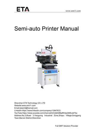
- 1. www.smt11.com Full SMT Solution Provider Semi-auto Printer Manual Shenzhen ETA Technology CO.,LTD Website:www.smt11.com Email:etasmt@foxmail.com LinkedIn:https://www.linkedin.com/company/13647672 YouTube:https://www.youtube.com/channel/UCrjQtG86plRI3ipGMSJwF5w Address:No.3,Road 3,Yangyong Industrial Zone,Shapu Village,Songgang Town,Bao’an District,Shenzhen
- 2. www.smt11.com Catalog I. Machine Performance Introduction II. Machine Specifications III. Name of Each Department Ⅳ. Electrical Panel Description V. Installation Sequence Instructions Ⅵ. Operation and Adjustment Methods Ⅶ. Circuit Diagram VIII. Touch Screen Operation Instructions Ⅸ. Maintenance Instructions Ⅹ. Simple Troubleshooting
- 3. www.smt11.com 1 Ⅰ. Machine Performance Introduction 1. Using precision motors and linear guides combined to make the blade holder printing stable. 2. Double-knife printing pressure uses the precise throttle valve behind the upper cylinder to set the blade speed, avoiding resonance. 3. The printing base can be lifted up 450 and fixed to facilitate scraper loading and unloading and screen cleaning. 4. The print base can be moved forward to fit the position of the steel plate pattern for better printing effect. 5. The high and low setting of the double scraper of the printing seat can be adjusted. 6. Printing plate and steel plate spacing, with fine adjustment bar scale setting. 7. Machine arm can be adjusted separately for 470 to 750mm different sizes. 8. The modular printing platen has a groove and positioning PIN, and the setting is simple. It is easy to change and is suitable for production of single-sided substrates and double-sided substrates. 9. The calibration plate method using arm (steel plate) movement and print (platen) X.Y.Z correction adjustment. Convenient and quick. 10. Pneumatic adopts microcomputer PLC control, man-machine interface touch control, and can freely choose single/double stroke printing.
- 4. www.smt11.com 2 II. Machine Specification Instructions Printing area 600* 250mm Printing platen 600* 320mm Max.screen frame size 750* 550mm Min. Screen frame size 470* 370mm Platen precision fine adjustment 1. Front and back ±6mm 2. Left and right ±6mm Voltage Single machine.220V.50/60HZ Air Pressure 5-7Kg/Cm2 Printing speed Set by VR scale display Dimension About 1100(L) * 700(W) * 1650(H)mm Weight About 300Kg
- 5. www.smt11.com 3 III. Name of Each Department 1 Machine base 10 Squeegee base 2 Electric and gas operating panels 11 Left limit----- Proximity switch 3 Printing platen 12 Right limit----- Proximity switch 4 X axis fine adjustment 13 Set hand wheel for printing pitch 5 Y axis fine adjustment 14 Air filter combination 6 Left arm 15 Motor 7 Right arm 16 Upper limit - magnetic switch 8 Left knife 17 Lower limit of a magnetic switch 9 Right knife 18 Start/reset buttons
- 6. www.smt11.com 4 IV.Electrical Panel Description 1. Microcomputer touch screen 2. Power control 3. Emergency stop 4. Speed potentiometer 5. Start button 6. Power indication
- 7. www.smt11.com 5 V. Installation Order Description 1. Installation location:Machine placement position, the surrounding can retain the channel, easy to machine correction and maintenance. 2. Machine fixed: The machine base of four feet cup, put less than four active wheels, fixed machine. 3. Power installation: This machine uses a 220V.50/60Hz power supply, please access at (3). 4. Air pressure installation: This machine uses 5-7Kg/cm2 compressed air, please access at (4). 5. Horizontal correction: Put a level instrument on the platen, adjust and fix the four foot.
- 8. www.smt11.com 6 VI. Machine Operation and Adjustment Essentials 1. Machine Station Origin Confirmation: After starting up (power transmission), the original point of self confirmation. 2. Zero Setting Essentials: Select the steel plate block rising down key, the steel plate down to the beginning point, the use of a ruler or PCB placed between the table and the seat into a horizontal line, while the distance between the mobile rotation scale to zero set, according to the thickness of the PCB to determine the printing spacing (generally according to the board thickness plus 40) 3. Printing setting Mode: The machine adopts movable positioning PI positioning, please according to the steel version of the sketch, put the PCB to the platform in a moderate position. 4. Version setting method: After completing the above (2) action, manual correction (Proofreading the print base and the printed circuit board) is performed again. For version guidelines: first set the R.C.L or pairing angle, after finding the target, fix the steel plate and use the platen to fine-tune the correction. 5. Printing Itinerary Setting Mode: After the completion of the PCB set alignment, and then use the printing block after the two induction switch, according to the steel version of the design, printing size set left and right induction switch position. 6. Knife assembly method: The knife is assembled using a center screw type. The center hole of the aluminum handle of the knife is used to fix a screw in accordance with the center of the knife. 7. Knife Height Adjustment Mode: First loosen the adjustment button's fixed screw, adjust the screw height namely is the knife height adjustment way. 8. Knife Elevation Adjustment Mode: Knife inside and outside use a single screw control elevation, front and rear screws need to be adjusted at the same time to control the knife front and rear elevation. 9. Printing Speed setting: (1) Printing gap: 2.0mm (general substrate thickness plus 40mm)
- 10. www.smt11.com 8
- 11. www.smt11.com 9 Ⅷ. Touch Screen Operation Instructions 1 Press the power control switch, turn on touch screen power for 5 seconds later will show you the following screen interface.
- 12. www.smt11.com 10 2 Then Touch English to enter the following interface (1)Touch the enter the Inching work status. (2)Touch the enter the semiautomatic work status. (3)Touch the to set the parameter. (4)Touch the enter the automatic work status. Note: In determining the work automatically, you must set the parameters, otherwise the machine will not work. Inching Semiautomatic Setting function Automatic
- 13. www.smt11.com 11 3 Automatic work status screen display (1) Touch to start automatic printing mode. This program is only used in the aging machine mode and cannot be used for production. (2) Touch to stop the automatic printing. (3) Touch return to home screen. Start Stop Exit
- 14. www.smt11.com 12 4 Inching work state screen display Touch in the home will show you the following screen. (1)Press Left knife moves up and down; (2)Press Right knife moves up and down; (3)Press 按下 Move printing left; (4)Press Move printing right; (5)Press the start button to print the net board up and down; Inching Right knife Left Printing Right Printing Left knife
- 15. www.smt11.com 13 5 Semi-automatic working images The following screen appears when you press the semi-automatic button on the start screen. Click START and press the two start buttons to start printing the PCB 6 Setting working screen Press Setting then below images appear
- 16. www.smt11.com 14
- 18. www.smt11.com 16 IX. Maintenance Introduction 1.Regularly clean the grease on the linear guide rails and cover with butter. Ensure that the blade runs smoothly.. 2.Regularly clean the foreign body up and down on the optical axis, and cover with butter. Protection the net board is unblocked. 3.Regularly check the synchronous wheel connected with the motor, if the timing belt is loose. 4.Regularly check the electrical box for any foreign objects and clean it. 5.Regular check the upper limit, lower limit, left limit, right limit, emergency stop, speed control knob, start switch with no damage and bad, if any damage should be immediately repaired or replaced. 6.Regularly check the upper and lower cylinders, left and right cylinders, solenoid valves, and gas lines without leakage. 7.Clean the foreign body in the plate hole of the perforated plate eegularly.
- 19. www.smt11.com 17 X. Simple troubleshooting Failure of the machine during operation, the display will show the number about 20 seconds. Please repair according to the following troubleshooting method. Fault display Fault conditions Failure reason and troubleshooting 51 1. The stencil board cannot rise 2. The stencil board cannot fall 1. The air pressure source is not input or air pressure is insufficient (normal air pressure should be kept at 4-6kg) 2. The rising top sensor is not sensed or damaged 3. The printing function is not set 4. The upper and lower cylinder regulator valves are defective or improperly adjusted. 52 1. The stencil board cannot drop 2. The squeegee cannot be printed left and right. 1. Up and down solenoid valve fault, IC plate failure; 2. The falling apex sensor is not sensed or has been damaged and is the relay. 53 1. Cannot be printed to the left after the stencil board has dropped. 2. Knife cannot be printed to the right. 3. The network board cannot fall Squeegee printed to the right to the right fixed point cannot stop the stencil board cannot rise. 1. The right sensor is not sensitive or damaged. 2. left and right drive motor power switch is not open or disconnected, converter failure, The right printing speed regulator is defective or damaged, and the motor is poor. 3. The right-hand drive relay is damaged or disconnected. 4. IC board failure. 54 1. Cannot be printed to the right after the stencil board has dropped. 2. Knife cannot be printed to the left. 3. The stencil board cannot fall Squeegee printed to the left to the left fixed point cannot stop the stencil board cannot rise. 1. The left sensor is not sensitive or damaged 2. left and right drive motor power switch is not open or disconnected, converter failure, The left printing speed regulator is defective or damaged, and the motor is poor. 3. The left-hand drive relay is damaged or disconnected. 4. IC board failure.
- 20. www.smt11.com 18 Welcome to inquiry any other equipment of our company. Special requirements can be customized. 55 The stencil board rises without printing. 1. Check whether the left and right sensors have been damaged or short-circuited. 2. The left and right sensors are interfered by the branch frequency. please connect a 0.1UF power supply container in parallel with the OUPUT. 56 No power input 1. Check if the power has been input; 2. Check if the power supply is broken or bad 3. Check if the power switch is damaged or bad; 4. Check if the fuse has been burned; 5. IC board failure 57 The converter cannot start or cannot drive the motor. 1. Converter parameter setting is wrong 2. The Converter is damaged 58 The squeegee cannot rise or fall 1. Squeegee cylinder drive electromagnetic fault 2. Squeegee cylinder speed control valve is bad or poorly adjusted 3. IC board failure As the company is constantly working on new product development and technological improvements, the parameters in this manual are subject to change without notice.
- 21. www.smt11.com 19 Company Profile ETA, a long-standing electronic equipment industry platform, has been continuously contributing to the global customer base in the field of electronics manufacturing since 1999. ETA company has excellent technical team and service team in surface mount technology (SMT), plug-in assembly (DIP), functional test (TEST), etc. in home appliances (Such as TV, refrigerator, air conditioner, washing machine), new energy (LED, Solar, new energy vehicles, automotive electronics, medical equipment, semiconductors, power electronics and other fields have many successful experiences. Our products cover SMT equipment (smt line, stencil printer, SPI, pick and place machine, AOI, reflow oven, handling equipment), DIP equipment (plug-in line, wave soldering machine, assembly line, belt line), test equipment, packaging equipment, etc. . Through the deepening of ETA's globalization strategy, we have helped more than 200 customers around the world to complete the entire industry chain from program design, production and construction, service training, etc. Our team and products have covered more than 150 countries all around the world and area. While exporting ETA's nearly 30 years of technical experience to global customers, we continue to improve our R&D capabilities and production capabilities. Through investment and equity acquisitions, ETA has more than 15 member companies in China, forming a supply chain for the entire industry chain system. In 2018, We helped clients plan to build more than 35 production workshops and train more than 100 technicians. In the next five years, our goal is to continue to focus on the electronics manufacturing industry, to provide more than 200 customers worldwide, and to provide more professional and active technical support for customers' manufacturing.