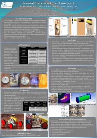
1. Chosen Cylinder Configuration from Research Designed Cylinder, Port Face and Port Block with CAD Software
1.0 Introduction/Aim
• The aim of this project was to create a teaching aid that would be a
useful tool for lecturers of Thermodynamics and Engineering Design
and Analysis.
• Testing of a physical model could help consolidate theory learned in
lectures and tutorials providing students with a better understanding of
the applications of what they have learned in the classroom.
• Stationary model steam engine with accompanying model car chassis.
• This was achieved through the following: - research, design,
manufacture, construction and testing of the model engine powered by
a pressurised vessel containing steam.
• Emphasis on safety through numerous steps
2.0 Design
• With different engine designs considered from research into different
configurations the engine was taken from the initial design stage .
• The most suitable design was chosen due to a variety of factors, eg. Cost
of Materials
• Engine components created using CAD software PTC Creo Parametric 2.0.
• The area using Pro Engineer proved to be most useful was collecting
dimensions for corresponding components disregarding then need for trial
and error when assembling components physically.
• Due to mix of bought in and designed components CAD software was key
in ensuring compatibility.
• Files created using CAD software were created with the intention that they
could be exported and made compatible with rapid prototyping and 3 axis
milling machines.
5.0 Results
• Construction of subassemblies including boiler with attachments, mounted
flywheel, connecting rod and crank a final assembly brought all parts
together as designed.
• CAD assemblies displayed dimensionally accurate model corresponding to
now fully constructed physical model.
• FEA Analysis of Boiler at working pressure validated boiler design and
material were fit for purpose.
4.0 Testing
• Variety of tests were carried out to prove that the fully constructed engine
was safe for its intended application environment.
• Testing was mainly focussed on the model brass boiler due to this
component being a pressurised vessel.
• Several procedures, including analytical calculations, static structural FEA
Analysis and physical testing were carried out to ensure its validity.
• Using these 3 methods, the boiler was tested to working pressure and to a
factor of safety of 3 of the working pressure.
• Boiler was subjected to hydraulic pressure tests conforming with British
Standard BS ISO 16528-1:2007
• Outcome of testing of various heat sources resulted in use of solid fuel.
• Fully constructed model was tested with compressed air to amend problems
with piston and crank synchronisation.
• Risk Assessments for use of naked flame and pressurised vessel in workshop.
Component Material Manufacturing
Process
Flywheel Aluminium 6082 3 Axis Machining
Piston & Cylinder Brass Die Casting/Lathe
Firebox Stainless Steel (SS) Fabrication
Chassis Stainless Steel (SS) Fabrication
Flywheel Mount Tricyclodecane
Diemethanol Dicrylate
Rapid Prototyping
Axle Flywheel Tricyclodecane
Diemethanol Dicrylate
Rapid Prototyping
Crank Tricyclodecane
Diemethanol Dicrylate
Rapid Prototyping
3.0 Manufacture
• There were a number of
manufacturing methods
exploited throughout the
construction of this model
steam engine.
• Parts chosen to be 3-Axis
machined were parts that
needed to be hard wearing
and of a suitable design as
to be compatible with the
machining process.
• Components picked for manufacturing through this method were chosen under
the assumption they were unlikely to be under large amounts of stress or high
temperatures.
• Fabrication was also used to create several components made from sheet metal
Internal
Pressure
Equivalent
Stress
(MPa)
Total
Deformation
(mm)
Fit for
Purpose
(Y/N)
15psi 10.468 3.8379e-3 Y
45psi 31.404 0.011514 Y
Ignition Temp Testing Solid Fuel with Infrared Camera Static Structural FEA Pressure Testing at Working Pressure (15psi)
Crank Position v Piston/Cylinder Position
6.0 Conclusions/Recommendations
• With design , manufacture, construction and testing completed it can be
concluded this model steam engine would be valuable as a teaching aid.
• With regards to recommendations researched for teaching applications ,
further work would be required with regards to construction of lesson plans.
• Further work that could complement this project could include :
1. Increasing boiler efficiency
2. Convection analysis using FEA software
3. Manufacture of all components
4. Inclusion of electronics
5. Closed system.
• Boiler was heated and steam
created allowed the engine to
run smoothly.
• Engine when run at designed
working pressure performed as
intended.
Acknowledgments
David Ross, Ian Hamilton, Colin Dalglish, Derek Leitch, Colin Russell
3 Axis Machining Process of Top Side of Flywheel D Rapid Prototyping of Flywheel Mount
Completed CAD Assembly of Model Steam Engine Successful Running of Steam Engine in Stationary Mode