surveying contouring
•Als PPTX, PDF herunterladen•
20 gefällt mir•16,475 views

surveying

Empfohlen
Weitere ähnliche Inhalte
Was ist angesagt?
Was ist angesagt? (20)
Andere mochten auch
Ähnlich wie surveying contouring
Ähnlich wie surveying contouring (20)
Kürzlich hochgeladen
Kürzlich hochgeladen (20)
surveying contouring
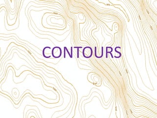
- 1. CONTOURS
- 2. • Contours are those lines you can see on OS maps. • A contour line is an imaginary line that joins points of equal height above sea level. • They can be used to learn about the shape of the land (the relief). • A map with only a few contour lines will be flat (and often low lying) • If a map has lots of contours it is a mountainous or hilly area. • The actual pattern of the lines will tell you more detail about the area too. Steep slopes Area that is flatter with only a gentle slope
- 3. CONTOURS • Contour An imaginary line on the ground surface joining the points of equal elevation is known as contour. • In other words, contour is a line in which the ground surface is intersected by a level surface obtained by joining points of equal elevation. This line on the map represents a contour and is called contour line. • Contour Map :-A map showing contour lines is known as Contour map. • A contour map gives an idea of the altitudes of the surface features as well as their relative positions in plan serves the purpose of both, a plan and a section.
- 4. Contouring • The process of tracing contour lines on the surface of the earth is called Contouring. • PURPOSE OF CONTOURING • Contour survey is carried out at the starting of any engineering project such as a road, a railway, a canal, a dam, a building etc. i) For preparing contour maps in order to select the most economical or suitable site. ii) To locate the alignment of a canal so that it should follow a ridge line. iii) To mark the alignment of roads and railways so that the quantity of earthwork both in cutting and filling should be minimum.
- 5. iv) For getting information about the ground whether it is flat, undulating or mountainous. v) To find the capacity of a reservoir and volume of earthwork especially in a mountainous region. vi) To trace out the given grade of a particular route. vii)To locate the physical features of the ground such as a pond depression, hill, steep or small slopes.
- 6. METHODS OF CONTOURING • There are mainly two methods of locating contours:- (1)Direct Method and (2) Indirect Method.
- 7. 1] Direct Method: • In this method, the contours to be located are directly traced out in the field by locating and marking a number of points on each contour. These points are then surveyed and plotted on plan and the contours drawn through them. • This method is most accurate but very slow and tedious as a lot of time is wasted in searching points of the same elevation for a contour. • This is suitable for small area and where great accuracy is required 50 48 B.M. DIRECT METHOD OF CONTOURING
- 8. Procedure: • To start with, a temporary B.M is established near the area to be surveyed with reference to a permanent B.M by fly levelling. • The level is then set up in such a position so that the maximum number of points can be commanded from the instrument station. • The height of instrument is determined by taking a back sight on the B.M. and adding it to the R.L. of bench mark. • The staff reading required to fix points on the various contours is determined by subtracting the R.L. of each of the contours from the height of instrument.
- 9. • Example: • If the height of instrument is 82.48m., then the staff readings required to locate 82, 81 and 80m contours are 0.48, 1.48 and 2.48m respectively. The staff is held on an approximate position of point and then moved up and down the slope until the desired reading is obtained. The point is marked with a peg. • Similarly various other points are marked on each contour. The line joining all these points give the required contour. It may be noted that one contour is located at a time. Having fixed the contours within the range of the instrument, the level is shifted and set up in a new position.
- 10. Procedure (Contd…..) • The new height of instrument and the required staff readings are then calculated in a similar manner and the process repeated till all the contours are located. The positions of the contour points are located suitably either simultaneous with levelling or afterwards. A theodolite , a compass or a plane table traversing is usually adopted for locating these points. The points are then plotted on the plan and the contours drawn by joining the corresponding points by dotted curved lines.
- 11. Direct Method By Radial Lines • This method is suitable for small areas, where a single point in the centre can command the whole area. Radial lines are laid out from the common centre by theodolite or compass and their positions are fixed up by horizontal angles and bearings. RADIAL LINES METHOD OF CONTOURING 70 65 60 55
- 12. Direct Method By Radial Lines (contd.): • Temporary bench marks are first established at the centre and near the ends of the radial lines . • The contour points are then located and marked on these lines and their positions are determined by measuring their distances along the radial lines. • They are then plotted on the plan and the contours drawn by joining all the corresponding points with the help of a plane table instrument.
- 13. 2. INDIRECT METHOD • In this method the points located and surveyed are not necessarily on the contour lines but the spot levels are taken along the series of lines laid out over the area . • The spot levels of the several representative points representing hills, depressions, ridge and valley lines and the changes in the slope all over the area to be contoured are also observed. • Their positions are then plotted on the plan and the contours drawn by interpolation. • This method of contouring is also known as contouring by spot levels.
- 14. • This method is commonly employed in all kinds of surveys as this is cheaper, quicker and less tedious as compared to direct method. There are mainly three method of contouring in indirect method: • (I) BY SQUARES [SQUARE METHOD]:- In this method, the whole area is divided into number of squares, the side of which may vary from 5m to 30m depending upon the nature of the ground and the contour interval. The square need not be of the same size throughout. • The corners of the squares are pegged out and the reduced levels of these points are determined with a level.
- 15. SQUARE METHOD
- 16. (II) By Cross- Sections: This method is most suitable for the survey of long narrow strips such as a road, railway or canal etc.
- 17. • (III) By Tacheometric method: • A techeometer is a transit theodolite having a diaphragm fitted with two stadia wires, one above and other below the central wire. The horizontal distance between the instrument and staff station may be determined by multiplying the difference of the staff readings of the upper and lower stadia wires with the stadia constant of the instrument, which is usually 100.Thus the techeometer is used for both the vertical as well as horizontal measurements. Stadia Wires at Diaphragm
- 18. iii) By Tacheometric method (contd…): • This method is most suitable in hilly areas as the number of stations which can be commanded by a techeometer is far more than those by a level and thus the number of instrument settings are considerably reduced. A number of radial lines are laid out at a known angular interval and representative points are marked by pegs along these radial lines. Their elevations and distances are then calculated and plotted on the plan and the contour lines are then interpolated.