Drilling Bit Introduction and bit Selection (Part 1)

(PART 1,2 & 3) 1. Drilling mechanisms 2. Bit classifications (fixed cutter and roller cone bits) 3. IADC code descriptions 4. Tri-cone bits life time 5. Geometrical analysis of roller cone bits • Fundamentals of bit design • Basics of cone geometry design • Oversize angle • Offset • Teeth and inserts • Additional design criteria: tooth to tooth and groove clearances and etc. • Cone-shell thickness • Bearings factors • Rock bit metallurgy • Heat treatment • Legs and cones material • Tungsten carbide materials • Legs and cones hard facing • Tungsten carbide grade selection for inserts • Bearings, seals and lubrication • Bearing shape • Bearing precisions and geometry • Seal systems and seal details • Dull grading system 6. Geometrical analysis of PDC bits • PDC materials and constructions • Matrix materials testing • Differs between matrix & steel body • Matrix body bits manufacturing • Steel body bits manufacturing • PDC bit design parameters: mechanical, hydraulic, rock properties • Weld strength of PDC bits and cutters • PDC cutter manufacturing process • Tsp cutter properties vs PDC • The influences of bit profile and profile elements • PDC forces • PDC bit stability • PDC bit steer-ability • Back rake • Side rake • Depth of cut • Cutter exposure • Cutter density • Thermal damage and degradation of cutters • Cutting mechanics • PDC cutter substrate and its thickness • Cutting structure elements • Single set bladed cutting structures • Plural set bladed cutting structures • Dull grading system 7. ROP management based on drilling parameters • WOB • Rpm • Sold content of mud • Mud weight • Cutter shape • Cutters geometry • Depth • Abnormal pressure • Drilling formation properties

Empfohlen
Weitere ähnliche Inhalte
Was ist angesagt?
Was ist angesagt? (20)
Ähnlich wie Drilling Bit Introduction and bit Selection (Part 1)
Ähnlich wie Drilling Bit Introduction and bit Selection (Part 1) (20)
Mehr von Amir Rafati
Mehr von Amir Rafati (6)
Kürzlich hochgeladen
Kürzlich hochgeladen (20)
Drilling Bit Introduction and bit Selection (Part 1)
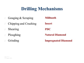
- 1. Drilling Mechanisms z z z z z Gouging & Scraping Milltooth Chipping and Shearing Ploughing Grinding Crushing Insert PDC Natural Diamond Impregnated Diamond Intro V1.1 22 August 2004
- 2. Bit Classification A Broad Overview
- 4. Bit Classification DrillBits Fixed Cutter Rolling Cutter P.D.C. Diamond Milltooth Insert Roller Bearing Friction BearingNatural Diamond Impregnated DiamondT.S.P. Intro V1.1 22 August 2004
- 5. Intro V1.1 22 August 2004 Bit Classification DrillBits Fixed Cutter Rolling Cutter P.D.C. Diamond Milltooth Insert Roller Bearing Friction BearingNatural Diamond Impregnated DiamondT.S.P.
- 6. Bit Classification DrillBits Fixed Cutter Rolling Cutter P.D.C. Diamond Milltooth Insert Roller Bearing Friction BearingNatural Diamond Impregnated DiamondT.S.P. Intro V1.1 22 August 2004
- 7. Bit Classification DrillBits Fixed Cutter Rolling Cutter P.D.C. Diamond Milltooth Insert Roller Bearing Friction BearingNatural Diamond Impregnated DiamondT.S.P. Intro V1.1 22 August 2004
- 8. Bit Classification DrillBits Fixed Cutter Rolling Cutter P.D.C. Diamond Milltooth Insert Roller Bearing Friction BearingNatural Diamond Impregnated DiamondT.S.P. Intro V1.1 22 August 2004
- 9. Bit Classification DrillBits Alternative Names Roller Cone Rock Bit Tri-Cone Fixed Cutter Rolling Cutter P.D.C. Diamond Milltooth Insert Roller Bearing Friction BearingNatural Diamond Impregnated DiamondT.S.P. Intro V1.1 22 August 2004
- 10. Bit Classification DrillBits Fixed Cutter Rolling Cutter P.D.C. Diamond Milltooth Insert Roller Bearing Friction BearingNatural Diamond Impregnated DiamondT.S.P. Intro V1.1 22 August 2004
- 11. Intro V1.1 22 August 2004 Bit Classification DrillBits Fixed Cutter Rolling Cutter P.D.C. Diamond Milltooth Insert Roller Bearing Friction BearingNatural Diamond Impregnated DiamondT.S.P.
- 12. Bit Classification DrillBits Fixed Cutter Rolling Cutter P.D.C. Diamond Milltooth Insert Roller Bearing Friction BearingNatural Diamond Impregnated DiamondT.S.P. Intro V1.1 22 August 2004
- 13. Intro V1.1 22 August 2004 Bit Classification DrillBits Fixed Cutter Rolling Cutter P.D.C. Diamond Milltooth Insert Roller Bearing Friction BearingNatural Diamond Impregnated DiamondT.S.P.
- 14. Bit Classification Application and I.A.D.C. Codes
- 15. IADC Codes Fixed Cutter S222 M419 S313 Roller Cone • • • • 5-1-7 1-3-5M 1-1-1 8-3-7X Intro V1.1 22 August 2004
- 17. - Insert Teeth Inserts 4-1Soft 8-3 Intro V1.1 22 August 2004 Hard 4 5 6 7 8 1 2 3
- 18. 1 Teeth Inserts Soft 1-3 4-1 Intro V1.1 22 August 2004 Hard 4 5 6 7 8 1 2 3
- 19. Teeth Inserts Diamond Soft Intro V1.1 22 August 2004 Hard 4 5 6 7 8 1 2 3
- 20. 1 Teeth Inserts Diamond P.D.C. Soft Intro V1.1 22 August 2004 Hard 4 5 6 7 8 1 2 3
- 21. 1 Teeth Inserts Diamond P.D.C. Impregnated Diamond Soft Intro V1.1 22 August 2004 Hard 4 5 6 7 8 1 2 3
- 22. Bit Application Spectrum Formation Compressive StrengthIntro V1.1 22 August 2004 PenetrationRate PDC Insert Mill Tooth Impreg & N.D.
- 23. Bit Classification Strengths and Weaknesses
- 24. Fixed Cutter Bits Advantages • Very Fast ROP • Long Life Potential Considerations • • • Impact Damage Abrasiveness Stability Intro V1.1 22 August 2004
- 25. Tooth Bits Advantages • • • • Fast ROP Good Stability Steerable Economic Considerations • Tooth Wear Rate • Bearing Life Intro V1.1 22 August 2004
- 26. Insert Bits Advantages • • • • Cutting Structure Durability Range of Formations Interbed Tolerance Steerability and Stability Considerations • Slower ROP • Bearing Life Intro V1.1 22 August 2004
- 27. Impregnated and Natural Diamond Bits Advantages • • • Very Durable Hard Rock Capability Low Junk-in-Hole Risk Considerations • • • Slower ROP RPM Sensitivity High Cost Applications Intro V1.1 22 August 2004
- 29. Drag Bits • Drag bits drill by physically plowing cuttings from the bottom of the borehole much like a farmer's plow cuts a furrow in the soil.
- 30. Drag Bits Properties • Advantage of drag bits over rolling cutting bits: – they do not have any rolling parts, which require strong, clean bearing surfaces. This is especially important in the small hole sizes, where space is not available for designing strength into both the bit cutter elements and the bearings needed for a rolling cutter. – Since drag bits can be made from one solid piece of steel, there is less chance of bit breakage, which would leave junk in the bottom of the hole. Removing junk from a previous bit can lead to additional trips to the bottom and thus loss of considerable rig time. • in soft formations that tend to be .. gummy," the cuttings may stick to the blades of a drag bit and reduce their effectiveness. This problem can be reduced by placing a jet so that drilling fluid impinges on the upper surface of the blade.
- 31. PDC BIT TYPES • “Matrix” is a very hard, rather brittle composite material comprised of tungsten carbide grains metallurgical bonded with a softer, tougher, metallic binder. • Steel is metallurgical an opposite to matrix: it is capable of withstanding high impact loads. But is, relatively soft and without protection, would protection, would quickly fail by abrasion and erosion.
- 32. PDC BIT TYPES • Design of matrix and steel-body bits • The lower impact toughness of matrix limits some matrix-bit features, such as blade height. Conversely, steel is ductile, tough, and capable of withstanding greater impact loads. This makes it possible for steel-body PDC bits to be relatively larger than matrix bits and to incorporate greater height into features such as blades. • Advantage of matrix-body PDC bits • Matrix-body PDC bits are commonly preferred over steel-body bits for environments in which body erosion is likely to cause a bit to fail. For diamond-impregnated bits, only matrix-body construction can be used. • Advantage of steel-body PDC bits • The strength and ductility of steel give steel-bit bodies high resistance to impact loading. Steel bodies are considerably stronger than matrix bodies. Because of steel material capabilities, complex bit profiles and hydraulic designs are possible and relatively easy to construct on a multi-axis, computer-numerically-controlled milling machine. A beneficial feature of steel bits is that they can easily be rebuilt a number of times because worn or damaged cutters can be replaced rather easily. This is a particular advantage for operators in low-cost drilling environments.
- 33. PDC BITS • The drill blanks consist of a layer of synthetic PDC about 1/64-in. thick that is bonded to a cemented tungsten carbide substrate in a high pressure high temperature process. • It contains many small diamond crystals bonded together. The cleavage planes of the diamond crystals have a random orientation that prevents any shock-induced breakage of an individual diamond crystal from easily propagating through the entire cutter.
- 34. PDC Cutters • Important cutter properties: – Cutter size – No. of Cutters – Cutter orientations: • must be properly matched to the hardness of the formation • In soft, formations, the orientation can be aggressive. • In abrasive formations orientation to prevent an excessive wear rate. • also depends on the cutter velocity, which in turn depends on the distance of the cutter location from the center of the hole.
- 35. Cutter orientations • Depth of Exposure – The exposure of the cutter provides room for the cutting to peel off the hole bottom without impacting against the bit body and packing in front of the cutter. • Back Rake angel (Negative) – 20 DEG negative back-rake angle is standard on PDC bits. smaller angles, suited for soft formations • Side Rake Angel – assists in pushing the cuttings formed to the side of the hole.
- 37. Offset • The drilling action of a rolling cutter bit depends to some extent on the offset of the cones. • Offsetting causes the cone to stop rotating periodically as the bit is turned and scrape the hole bottom much like a drag bit. This action tends to increase drilling speed in most formation types. • it also promotes faster tooth wear in abrasive formations. • Cone offset angle varies from about 4 DEG for bits used in soft formations to zero for bits used in extremely hard formations. • The drilling action of a bit with zero cone offset is essentially a crushing action.
- 38. Journal Angle – One of the basic design fundamentals of rolling cutter rock bits is the journal angle. – The journal angle is the angle at which the journal is mounted, relative to a horizontal plane.
- 39. Shape of Bit Teeth • It has a large effect on the drilling action of a rolling cutter bit. Long, widely spaced, steel teeth are used for drilling soft formations. • The long teeth easily penetrate the soft rock, and the scraping twisting action provided by alternate rotation and plowing action of the offset cone removes the material penetrated. • Teeth cleaning action is provided by the intermeshing of teeth on different cones and by fluid jets between each of the three cones. • As the rock type gets harder, the tooth length and cone offset must be reduced to prevent tooth breakage. • The smaller teeth also allow more room for the construction of stronger bearings
- 40. Cutter Types • The milled tooth cutters are manufactured by milling the teeth out of a steel cone. • Tungsten carbide insert cutters are manufactured by pressing a tungsten carbide cylinder into accurately machined holes in the cone.
- 41. Inner & outer Cutter Rows • The inner rows of teeth are intermeshed positioned. 1. allows more room for a stronger bit design. 2. provides a self-cleaning action as the bit turns. 3. allows maximum coverage of the hole for a given number of teeth. • The bottom-hole coverage of most bits is about 70%. • The outer row of teeth on each cone do not intermesh. • This row of teeth called the heel teeth. • Due to the circular geometry has by far the hardest job. – more rock must be removed from the outermost annular ring of the hole bottom. – this rock is more difficult to remove because it tends to remain attached to the borehole wall.
- 42. Inner & outer Cutter Rows • Because the heel teeth have a more difficult job they may wear excessively. • causing the bit to drill an out-of-gauge hole. • This causes a gross misalignment of the load on the bearings and premature bit failure. Premature failure of the next bit is also likely if the hole remains undersized. • Most bit manufacturers offer more than one heel tooth design with a given bit type so the drilling engineer may obtain the amount of gauge protection needed.
- 43. Roller types • The standard or most inexpensive bearing assembly: – a roller-type outer bearing. – a ball-type intermediate bearing. – a ball or friction-type nose bearing.
- 44. Roller types • The roller-type outer bearing is the most heavily loaded member and usually tends to wear out first. The race that the roller bearing rolls over tends to spall and wear on the bottom side where the weight applied to the bit is transmitted from the pin to the cone. • The intermediate ball bearings carry primarily axial or thrust loads on the cones. They also serve to hold the cone in place on the bit. • The nose bearings are designed to carry a portion of the axial or thrust loads after the ball bearings begin to wear. The nose bearing is a friction-type bearing in most bit sizes. but in the larger bit sizes another roller bearing is used.
- 45. Standard Bearings • In the standard bearing design. all bearings are lubricated by the drilling fluid. When a gas is used as the drilling fluid, a modified bit is available with passageways permitting a portion of the gas to flow through the bearing assembly The intermediate-cost bearing assembly used in rolling cutter bits is the sealed bearing assembly.
- 46. Sealed bearing • the bearings are maintained in a grease environment by grease seals. a grease reservoir. and a compensator plug that allows the grease pressure to be maintained equal to the hydrostatic fluid pressure at the bottom of the hole. • While the grease seals require some space and. thus. a reduction in bearing capacity. The elimination of abrasive material from the bearings usually more than compensates for this disadvantage. • As the bit wears, the grease seals eventually fail and the drilling fluid can enter the bearings and accelerate the bearing wear.
- 47. Journal bearing bits • In this type bit, the roller bearings are eliminated and the cone rotates in contact with the journal bearing pin. • This type bearing has the advantage of greatly increasing the contact area through which the weight on the bit is trans mitted to the cone. • Also, by eliminating one of the components (the rollers), additional space becomes available for strengthening the remaining components. • Journal bearing bits require effective grease seals, special metallurgy, and extremely close tolerances during manufacture. – Silver inlays in the journal help to minimize friction and prevent galling.
- 48. Bit Nozzle Types
- 51. TRI-CONE IADC Classify (First No.)
- 52. TRI-CONE IADC Classify (First No.)
- 53. TRI-CONE IADC Classify (Sec No.)
- 54. BEARING TYPES (third No.) • Roller or open bearing. • Sealed Roller Bearing. • Friction bearing or sealed journal bearing. • Air Blast
- 55. Roller or open bearing • Open bearing bits are easily distinguished by its IADC code with the final number being either a 1, 2 or 3. One is open bearing without shank protection, two is without shank protection and suitable for air drilling, and three is with shank protection.
- 56. Sealed Roller Bearing • Once the seal is worn and is no longer good, the drill bit still has some life left and will perform like an roller bearing drill bit. • The final number will either be a 4 or a 5. Four denotes sealed roller bearing without shank protection, five is with shank protection.
- 57. Friction bearing or sealed journal bearing • Used in Directional Drilling. Due to the extra wear on the shank, gage inserts are placed on the shank for extra protection. • The final IADC number will be a 6 or a 7. Six is a sealed journal bearing without shank protection & seven is with shank protection.
- 59. TRI-CONE IADC Classify (Forth No.)
- 60. TRI-CONE IADC Classify (Forth No.)
- 61. IADC EXAMPLE • 135 • 517M • 111 • 215 • 447 • 527 • 135A • 111C
- 62. Bit WORKING Parameters • Rule of thumb COND. for TRI-CONE RPM & WOB: – WOB Range: 2 to 5 Klb/in – RPM Range: 30 to 180 round per minute – Ex.: WOB = 36 Klb/in & RPM=120 for 12 1/4” B.bit with IADC=517 • Rule of thumb COND. for PDC RPM & WOB: – WOB Range: 1 to 3 Klb/in – RPM Range: 30 to 360 (with Motor) round per minute – Ex.: WOB= 25 Klb/in & RPM=230 for 12 1/4” PDC with IADC=M123
- 63. Life of Tri-cone Bits • IADC IS NOT Enough. • TBR (TOTAL BEARING REVOLUTION) Must be Considered in REAL drilling for Bit Selection – It means that Revolutions of bit must be simulated as Real condition ie. In a field for Drilling 12 ¼” bore hole average WOB is 40 klb and 120 RPM so Real Life of Satisfied bit must be Defined in this condition: • WOB=40 Klb/in RPM=120 TBR=800 K.revs
- 64. Rock Failure Mechanisms (I) Wedging, (II) Scraping and grinding (III) Erosion by fluid jet action (IV) Percussion or crushing, (V) Torsion or twisting. To some extent, these mechanisms are interrelated.
- 65. Rock Failure Mechanisms (I) Wedging, (II) Scraping and grinding (III) Erosion by fluid jet action (IV) Percussion or crushing, (V) Torsion or twisting. To some extent, these mechanisms are interrelated.
- 66. Failure Mechanisms of Drag Bits • Drag bits are designed to drill primarily by a wedging mechanism. • If drag bits could be kept drilling by wedging, they would not dull so quickly. • A twisting action also may contribute to rock removal The cuttings are sheared off in a shear plane at an initial angle to the plane of thrust that is dependent on the properties of the rock. • The depth of the cut is controlled by the plane of thrust and is selected based on the strength of the rock and the radius to the cut. The depth of the cut is often expressed in terms of the bottom cutting angle.
- 67. Failure Mechanisms of Drag Bits • The bottom clearance angle prevents the wedge from dragging the bottom while taking a chip and, thus, causing the bit to jump and chatter and to wear fast. • A slight rake angle can help promote an efficient wedging mechanism, although a positive rake angle may not be necessary because of the downward slope of the hole bottom when the bit is operated properly. • The bit tooth loses strength as the rake angle is increased.
- 68. Failure Mechanism of Rolling Cutter Bit
- 69. Failure Mechanism of Rolling Cutter Bit
- 70. Bit Selection • best available bit for can be determined only by trial and error. • The most valid criterion for comparing the performance of various bits is the drilling cost per unit interval drilled. – Cf = Cb + Cr (tb + tc + tt) / D WHERE • Cf is cost per ft • Cr is cost of the rig per hr • tb is total rotating time during the bit run • tc is non-rotating time during the bit run • tt is trip time • D is the target well depth
- 71. Drill ability and Abrasiveness • DRILLABILITY is a measure of how easy the formation is to drill. • Drill ability: decrease with depth in a given area. • Abrasiveness: measure of how rapidly the teeth of a milled tooth bit will wear.
- 72. bit selection rules of thumb 1. The IADC classification charts provide an approximate listing of the bit in a given formation hardness. 2. The should be governed by bit cost considerations. 3. Three-cone bits are a good choice for the shallow portion of the well. 4. PDC perform best in uniform sections of carbonates or evaporates that are not broken up with hard shale stringers or other brittle types.
- 73. drill ability and abrasiveness 5. When using a rolling-cutter bit: a) Use the longest tooth size possible. b) A small amount of tooth breakage should be tolerated rather than selecting a shorter tooth size. c) When enough weight cannot be applied economically to a milled tooth bit to cause self sharpening tooth wear, a longer tooth size should be used. d) When the rate of tooth wear is much less than the rate of bearing wear, select a longer tooth size, a better bearing design, or apply more bit weight vice versa. 6. PDC bits perform best in non-brittle formations having a plastic mode of failure, especially in the bottom portion of a deep well, where the high cost of tripping operations favors a long bit life, and a small hole size favors the simplicity of a drag bit design. 7. PDC drag bits should not be used in gummy formations.
- 74. IADC BIT DULL GRADING
- 75. IADC BIT DULL GRADING
- 76. 1,2: Grading Bit Wear • Teeth Wear:
- 77. 1,2: Dull Grading Locations
- 78. 3: Dull Characteristics BC - Broken Cone BT - Broken Teeth BU - Balled Up CC - Cracked Cone CD - Cone Drag CI - Cone Interference CR – Cored CT - Chipped Teeth ER – Erosion FC - Flat Crested Wear HC - Heat Checking JD - Junk Damage LC - Lost Cone LN - Lost Nozzle LT - Lost Teeth NO - No Dull Characteristics NR - Not Rerun-able OC - Off Center Wear PB - Pinched Bit PN - Plugged Nozzle RG - Rounded Gauge RR – Rerun-able SD - Shirttail Damage SS - Self Sharpening Wear TR – Tracking WO - Washed Out WT - Worn Teeth
- 79. BC - Broken Cone • Some of the causes of BC are: • Cone interference • Bit hitting a ledge on trip or connection. • Dropped drill string. • Hydrogen sulfide embrittlement. • BF (Bond Failure) • Refers to Fixed Cutter Dull Condition
- 80. BT - Broken Teeth • Some causes of BT are: • Bit run on junk. • Bit hitting a ledge or hitting bottom suddenly. • Excessive WOB for application. broken teeth on the inner and middle row teeth. • Excessive RPM for application. broken teeth on the gauge row teeth. • Improper break-in of bit when a major change in bottom-hole pattern is made. • Formation too hard for bit type.
- 81. BU - Balled Up • Some causes of bailing up are: • Inadequate hydraulic cleaning of the bottom-hole. • Forcing the bit into formation cuttings with the pump not running. • Drilling a sticky formation.
- 82. CC - Cracked Cone • Some of these causes are: • Junk on the bottom of the hole. • Bit hitting a ledge or bottom. • Dropped drill string. • Hydrogen sulfide embrittlement. • Overheating of the bit. • Reduced cone shell thickness due to erosion. • Cone interference.
- 83. CD - Cone Drag • Some of the possible causes are: • Bearing failure on one or more of the cones. • Junk lodging between the cones. • Pinched bit causing cone interference. • Bit bailing up. • Inadequate break in.
- 84. CI - Cone Interference • Some of the causes of cone interference are: • Bit being pinched. • Reaming under gauge hole with excessive WOB. • Bearing failure on one or more cones.
- 85. CR – Cored • A bit can be cored when the nose part of one or more cones is broken. • Some things that can cause bits to become cored are: • Abrasiveness exceeds the wear resistance of the center cutters. • Improper breaking in of a new bit when there is a major change in bottom-hole pattern. • Cone shell erosion resulting in lost cutters. • Junk in the hole causing breakage of the center cutters.
- 86. CT - Chipped Teeth • Some causes of chipped teeth are: • Impact loading due to rough drilling. • Slight cone interference. • Rough running in air drilling application.
- 87. ER – Erosion • Abrasive contacting the cone shell between the cutters, caused by tracking, off-center wear, or excessive WOB. • Abrasive cuttings eroding the cone shell due to inadequate hydraulics. • Excessive hydraulics resulting in high velocity fluid erosion. • Abrasive drilling fluids or poor solids control.
- 88. FC - Flat Crested Wear • Low WOB and high RPM, often used in attempting to control deviation.
- 89. HC - Heat Checking • Some situations can cause heat checking are: • Cutters being dragged. • Reaming a slightly under gauge hole at high RPM.
- 90. JD - Junk Damage • Junk dropped in the hole from the surface • Junk from the drill • Junk from a previous bit • Junk from the bit itself
- 91. LC - Lost Cone • Bit hitting bottom or a ledge on a trip or connection. • Dropped drill string. • Bearing failure (causing the cone retention to fail). • Hydrogen sulfide embrittlement.
- 92. LN - Lost Nozzle • A lost nozzle causes a pressure decrease which requires that the bit be pulled out of the hole. • A lost nozzle is also a source of junk in the hole. • Improper nozzle installation. • Improper nozzle and/or nozzle design. • Mechanical or erosion damage to nozzle or retainer.
- 93. LT - Lost Teeth • Lost teeth often cause junk damage. • Lost teeth are preceded by rotated inserts. • Cone shell erosion. • A crack in the cone that the grip on the insert. • Hydrogen sulfide embrittlement cracks.
- 94. OC - Off Center Wear • Change of formation from a brittle to a more plastic formation. • Inadequate stabilization in a deviated hole. • Inadequate WOB for formation and bit type. • Hydrostatic pressure that significantly exceeds the formation pressure.
- 95. PB - Pinched Bit • Bit being forced into under gauge hole. • Roller cone bit being forced into a section of hole drilled by fixed cutter bits, due different OD tolerances. • Forcing a bit through casing that does not drift to the bit size used. • Bit being pinched in the bit breaker. • Bit being forced into an undersized blow out preventer stack.
- 96. PN - Plugged Nozzle • A plugged nozzle can lead to reduced hydraulics or force a trip out of the hole due to excessive pump pressure. • Jamming the bit into fill with the pump off. • Solid material going up the drill string through the bit on a connection and becoming lodged in a nozzle when • circulation is resumed. • Solid pumped down the string, become lodged in a nozzle.
- 97. RG - Rounded Gauge • The gauge inserts may be less than nominal bit diameter but the cone back-faces are still at nominal diameter. • Drilling abrasive formation with excessive RPM • Reaming an under gauge hole.
- 98. SD - Shirttail Damage • Shirttail wear can lead to seal failures. • Junk in the hole. • Reaming under gauge hole in faulted or broken formations. • A pinched bit causing the shirttails to be the outer most part of the bit. • Poor hydraulics. • High angle well bore.
- 99. SS - Self Sharpening Wear • This is a dulling characteristic which occurs when cutters wear in a manner such that they retain a sharp crest shape.
- 100. TR – Tracking • Tracking can sometimes be alleviated by using a softer bit to drill the formation and/or by reducing the hydrostatic pressure if possible. • Formation changes from brittle to plastic. • Hydrostatic pressure that significantly exceeds the formation pressure.
- 101. WO - Washed Out • If the bit weld is porous or not closed, the bit will start to washout as soon as circulation starts. • Often the welds are closed but crack during the bit run due to impact with bottom or ledges on connections.
- 102. WT - Worn Teeth • When WT is noted for steel tooth bits, it is also often appropriate to note self sharpening (SS) or flat crested (FC) wear.
- 103. No-No Dull Characteristics • This is often used when a bit is pulled after a short run for a reason not related to the bit, such as a drill string washout.
- 104. 4: Locations
- 105. 5: Bearing Seals • PDC X • Non-Sealed Bearings A linear scale estimating bearing life used 0 - No life used 8 - All life used, • Sealed Bearings E - Seals effective F - Seals failed N - Not able to grade
- 106. 6: Measuring Gauge Gage = 2/3 x
- 107. Other Dull Characteristics • (Refer to column 3 codes)
- 108. Reason Pulled or Run Terminated • BHA - Change Bottom-hole Assembly • CM - Condition Mud • CP - Core Point • DMF – Down-hole Motor Failure • DP - Drill Plug • DSF - Drill String Failure • DST - Drill Stem Test • DTF – Down-hole Tool Failure • FM - Formation Change • HP - Hole Problems • HR - Hours on Bit
- 109. Reason Pulled or Run Terminated • LIH - Left in Hole • LOG - Run Logs • PP - Pump Pressure • PR - Penetration Rate • RIG - Rig Repair • TD - Total Depth/Casing Depth • TQ - Torque • TW - Twist Off • WC - Weather Conditions • WO - Washout - Drill String
- 110. Factors Affecting Penetration Rate 1. bit type 2. formation characteristics 3. drilling fluid properties 4. bit operating conditions – bit weight – rotary speed 5. bit tooth wear 6. bit hydraulics.
- 111. bit type • rolling cutter bits: the initial ROP is often highest in a given formation when using bits with • long teeth and a large cone offset angle. • Used only in soft formations because of a rapid tooth Wear Decrease ROP in hard formation. • Drag bits: give a wedging type rock failure in which the bit ROP per revolution depends on the number of blades and the bottom cutting angle. • The width and cutters can be used to compute the effective number of blades. The length of the cutters projecting from the face of the bit limits the depth of the cut.
- 112. formation characteristics • The elastic limit and ultimate strength of the formation affecting ROP • the crater produced beneath a single tooth is inversely proportional to: – compressive strength of the rock – shear strength of the rock. • The permeability of the formation also has a significant effect on the penetration rate. • the mineral composition of the rock also has some effect on penetration rate.
- 113. Drilling Fluid Properties 1. density 2. rheological flow 3. filtration characteristics 4. solids content and size distribution 5. chemical composition • ROP tends to decrease with increasing fluid density, viscosity. and solids content, and tends to increase with increasing filtration rate
- 114. bit operating conditions bit floundering
- 115. Drill-off test
- 116. Drill-off test
- 117. Penetration Rate Equation • D = true vertical well depth, ft, • gp = pore pressure gradient, Ibm/gal. • ρe= equivalent circulating density, • (Wldb)t = threshold bit weight per inch of bit diameter at which the bit begins to drill, 1.000 lbf/in., • h = fractional tooth dullness, • Fj = hydraulic impact force beneath the bit lbf • A1 to a8 = constants that must be chosen based on local drilling conditions. • Example 1 • Example 2
- 118. Drilling Cost Analysis • Example 1 • Example 2