Shriners Gait Lab Foot Model Presentation, GCMAS 2015
•
1 gefällt mir•1,048 views

Presentation of the modified Shriners Hospital for Children, Greenville Foot Model, as implemented in the Shriners Gait Lab in Vancouver BC. This is a foot model used daily in the clinic to help understand foot anomalies in children with Cerebral Palsy, Spina Bifida and Clubfeet

Empfohlen
Empfohlen
Weitere ähnliche Inhalte
Was ist angesagt?
Was ist angesagt? (20)
Ähnlich wie Shriners Gait Lab Foot Model Presentation, GCMAS 2015
Ähnlich wie Shriners Gait Lab Foot Model Presentation, GCMAS 2015 (20)
Kürzlich hochgeladen
Kürzlich hochgeladen (20)
Shriners Gait Lab Foot Model Presentation, GCMAS 2015
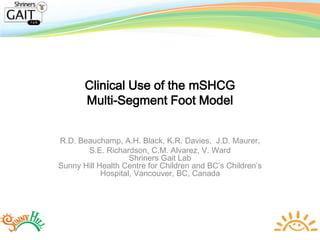
- 1. Clinical Use of the mSHCG Multi-Segment Foot Model R.D. Beauchamp, A.H. Black, K.R. Davies, J.D. Maurer, S.E. Richardson, C.M. Alvarez, V. Ward Shriners Gait Lab Sunny Hill Health Centre for Children and BC’s Children’s Hospital, Vancouver, BC, Canada
- 2. SGL Vancouver • .5 fte Director • 1.0 Engineer • .8 PT (shared by 2) • 2 Orthopaedic Surgeons
- 3. Mandate • To provide clinical decision support to Orthopaedic Surgeons, Physiotherapists and Orthotists • To conduct clinically relevant research to aid our decision support role
- 5. History of MSFM • 2004 – GCMAS Foot Modeling Symposium • 2004 – 2 Mech Eng Students OFM in V3D • 2007 – Hired an Engineer • 2008 – Compared the OFM to other models • 2010 – Settled on Shriners Hospital for Children Greenville (SHCGFM)
- 6. Presentations • Maurer, J. D., Black, A.H., Alvarez, C. M., Ward, V., Davies, K R., & Beauchamp, R. D.(2009). Classification of Mid-foot Break Using a Multi-segment Foot Model. GCMAS (Vol. 23, pp. 204–205). Denver, Colorado. • Maurer, J. D., Black, A.H., Alvarez, C. M., Ward, V., Davies, K. R., & Beauchamp, R. D. (2010). Classification of Mid-foot Break Using a Multi-segment Foot Model. 2nd Congress of the International Foot and Ankle Biomechanics Community (Vol. 23). • Black, A. H., Maurer, J. D., Alvarez, C. M., Ward, V., Davies, K. R., Mayson, T. A., & Beauchamp, R. D. (2012). CLASSIFICATION OF MID-FOOT BREAK USING A MULTI- SEGMENT FOOT MODEL AND PEDOBAROGRAPHY. In Gait & Clinical Movement Analysis Society 2012 Annual Conference (pp. 185–186). Grand Rapids Michigan.
- 8. Shank • Coordinate System Alignment: The shank coordinate system (right shank is used for this example) is aligned with the plane formed by Right_Knee (mid-point of R.KNEE and R.KNEE.MEDIAL), R.ANKLE, and R.ANKLE.MEDIAL. Proximal End: Right_Knee Distal End: Right_Ankle - mid-point between R.ANKLE and R.ANKLE.MEDIAL Tracking Markers: R.ANKLE, R.KNEE, R.SHANK
- 9. Foot • Coordinate System Alignment: The virtual foot coordinate system (right foot is used for this example) is aligned with the plane formed by R.HEEL, R.TOE, and RCAL2. Proximal End: R.Heel Distal End: R.Toe Tracking Markers: R.HEEL, R.TOE, RP1MT, RP5MT
- 10. Hindfoot • Coordinate System Alignment: The hindfoot coordinate system (right foot is used for this example) is aligned with the plane formed by R.HEEL, RT_Cal_Midpoint, and RCAL2. The vector from R.HEEL to RT_Cal_Midpoint_Projected (Cal Mid- point is offset such that this vector is parallel to the ground) forms the Y- axis, the X-axis is perpendicular to the hindfoot plane (described above), and the Z-axis is orthogonal to X and Y. Proximal End: R.Heel Distal End: RT_Cal_Midpoint Tracking Markers: R.HEEL, RMCAL, RLCAL, RLCAL2
- 11. Forefoot• Coordinate System Alignment: The forefoot coordinate system is set parallel to the floor at the same height as the heel marker (for convenience to match the HF coordinate system). The forefoot origin (R_Forefoot_Origin) is located at RP2ND, projected onto the forefoot plane described above. The vector from R_Forefoot_Origin to R_Forefoot_Distal (the R.Toe marker projected onto the forefoot plane) forms the Y-axis, the X-axis is perpendicular to the Y-axis, within the forefoot plane, and the Z-axis is orthogonal to X and Y. Proximal End: R_Forefoot_Origin Distal End: R_Forefoot_Distal Tracking Markers: RP5MT, RD5MT, RP1MT and R.TOE
- 12. Repeatability • Intra/Inter tester Reliability. • 2 PT’s , 1 adult , 3 sessions • mSHCGFM forefoot angles: PT1(M 5.8°, SD 1.5°) PT2 (M 6.5°, SD 0.7°) • mSHCGFM hindfoot angles: PT1(M 7.1°, SD 2.3°) PT2 (M 6.0°, SD 1.2°)
- 16. What’s Wrong With a Mid-Foot Break (MFB)? • Pain • Foot Mechanics – lever arm dysfunction • Reduced moment arm • Reduced power generation
- 17. Ways to Identify MFB • Clinical • Radiographic • Plantar Pressures • Kinematics
- 18. Clinical • Sagittal Plane: – HF in equinus – FF dorsiflexed relative to HF • Coronal Plane: – HF valgus – FF pronated • Transverse Plane: – FF abducted
- 19. Davids, J.R. et al. J Pediatr Orthop 25, 769-76 (2005). Normal X-Ray MFB X-Ray A C
- 20. Pedobarography
- 21. Kinematics a new perspective on MFB Normal MFB
- 22. Forefoot and hindfoot angles with respect to the lab. FF = solid line, HF = dotted line. Black: Normal Mean, n=30. Red: MFB Mean, n=30. Normal MFB
- 23. MFB Vs Normal Forefoot and hindfoot angles with respect to the lab. FF = solid line, HF = dotted line. Black: Normal Mean, n=30. Red: MFB Mean, n=30. • In the MFB Group, the HF moves into plantarflexion starting at foot strike, while the FF remains in contact with the floor initially and moves into plantarflexion at a slower rate. • Relative to the floor, there was a much greater difference between the FF and HF angle in the MFB group (p<.05). • 17.1 +/-5.5 deg (MFB) • 6.2 +/- 2.1 deg (Normal) 17.1 +/-5.5 deg 6.2 +/- 2.1 deg
- 24. Clinical Case 1 • 8 year old female with CP Diplegia • GMFCS level 2 • FMS in 2009 4, 3, 3 • FMS in 2011 5, 5, 3
- 25. Pre-Op Xray
- 26. Pre-op/Post-op Comparison • bilateral gastrocnemius recessions Surgery:
- 27. Post-Op Xray
- 28. Pre-op
- 29. Post-Op
- 31. Kinematics
- 32. Kinematics
- 33. Clinical Case 2 • 12 yr old male with Diplegic CP • 2013 Bilateral calcaneal lengthenings, gastroc recessions, H/S releases, RF transfer, LT peroneal lengthening • Pre-op FMS 6,5,5 • GMFCS 2 • GDI 67 bilaterally
- 34. Pre-op Xray
- 35. Video
- 37. Video
- 38. Video
- 39. Foot Kinematics
- 40. Foot Kinematics
- 41. Post Op
- 42. Post-Op Xray
- 43. Post Op
- 44. Post Op
- 45. Kinematics
- 46. Conclusion • By using the mSHCGFM, it is now possible to quantify the presence and severity of MFB in children in the sagittal plane and monitor the progression over time.
- 47. Future Directions • Examine forefoot and hindfoot motion in coronal and transverse planes • Application to Clubfoot
- 50. References • Maurer, Jessica D, Valerie Ward, Tanja a Mayson, Karen R Davies, Christine M Alvarez, Richard D Beauchamp, and Alec H Black. 2013. “A Kinematic Description of Dynamic Midfoot Break in Children Using a Multi-Segment Foot Model.” Gait & Posture 38 (2) (June 27): 287–92. doi:10.1016/j.gaitpost.2012.12.002. http://www.ncbi.nlm.nih.gov/pubmed/23273965. • Maurer, Jessica D, Valerie Ward, Tanja a Mayson, Karen R Davies, Christine M Alvarez, Richard D Beauchamp, and Alec H Black. 2014. “Classification of Midfoot Break Using Multi-Segment Foot Kinematics and Pedobarography.” Gait & Posture 39 (1) (January 19): 1–6. doi:10.1016/j.gaitpost.2013.08.015. http://www.ncbi.nlm.nih.gov/pubmed/24001869.
- 51. Thank You