

Empfohlen
Weitere ähnliche Inhalte
Andere mochten auch
Mehr von Akshay Sharma
Mehr von Akshay Sharma (10)
Kürzlich hochgeladen
Kürzlich hochgeladen (20)
Est 7
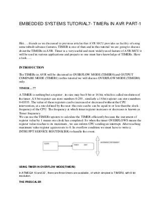
- 1. EMBEDDED SYSTEMS TUTORIAL7- TIMERs IN AVR PART-1 Hiii…..friends as we discussed in previous articles that AVR MCU provides us facility of using some inbuilt advance features, TIMER is one of then and in this tutorial we are going to discuss about the TIMERs in AVR. Timer is a very useful and most widely used feature of AVR MCU it will be used in various applications and projects so one must have knowledge of TIMERs. Have a look….. INTRODUCTION The TIMERs in AVR will be discussed in OVERFLOW MODE (TIMER0) and OUTPUT COMPARE MODE (TIMER1) in this tutorial we will discuss OVERFLOW MODE (TIMER0) only. TIMER…?? A TIMER is nothing but a register . its size may bee 8 bit or 16 bit, which is called resolution of the timer. A 8 bit register can store numbers 0-255 , similarly a 16 bit register can store numbers 0-65535. The value of these registers can be increased or decreased without the CPU intervention, at a rate defined by the user. this rate can be can be equal to or less than the clock frequency of the CPU. The frequency at which timer register increases or decreases is known as Timer frequency. We can use the TIMER registers to calculate the TIMER efficiently because the increment of register value by 1 means one clock has completed. So when the timer OVERFLOWS means the register value reaches to its maximum , we can inform CPU sending an interrupt. After reaching maximum value register again resets to 0. In overflow condition we must have to write a INTRUPPT SERVICE ROUTINE(ISR) to handle the event. USING TIMER IN OVERFLOW MODE(TIMER0) In ATMEGA 16 and 32 , there are three timers are available , of which simplest is TIMER0, with 8 bit resolution. THE PRESCALER
- 2. The Prescaler is a mechanism for generating clock for timer by the CPU clock. As you know that CPU has a clock source such as a external crystal of internal oscillator. Normally these have the frequency like 1 MHz,8 MHz, 12 MHz or 16MHz(MAX). The Prescaler is used to divide this clock frequency and produce a clock for TIMER. The Prescaler can be used to get the following clock for timer. No Clock (Timer Stop). No Prescaling (Clock = FCPU) FCPU/8 FCPU/64 FCPU/256 FCPU/1024 TIMER0 REGISTERS. Here is the description of some register of TIMER0 , which we are going to useTCCR0 – TIMER COUNTER CONTROL REGISTER This register is used configure the timer. As you can see there are 8 Bits in this register each used for certain purpose. For this tutorial I will only focus on the last three bits CS02 CS01 CS00 They are the CLOCK SELECT bits. They are used to set up the Prescaler for timer. TCNT0 – TIMER COUNTER 0 This register is the main counter in the TIMER0. The timer clock counts only this register as 1. It means tomer clock will increase the value of this 8 bit register by 1 every timer clock pulse.
- 3. TIMSK- TIMER INTRUPPT MASK REGISTER This register is used to activate/deactivate interrupts related with timers. This register controls the interrupts of all the three timers. The last bit BIT0 Controls the interrupts of TIMER0. TOIE0 : This bit when set to “1” enables the OVERFLOW interrupt. PROGRAMMING PRESCALER- 1024 CLOCK FREQUENCY- 16 MHz Clock input of TIMER0 = 16MHz/1024 = 15625 Hz Frequency of Overflow = 15625 /256 = 61.0352 Hz if we increment a variable “count” every Overflow when “count reach 61” approx one second has elapse. If count reaches 61 we will toggle PB0 which is connected to LED and reset “count= 0”. SETTING UP THE TIMER0 // Prescaler = FCPU/1024 TCCR0|=(1<<CS02)|(1<<CS00); //Enable Overflow Interrupt Enable TIMSK|=(1<<TOIE0); //Initialize Counter TCNT0=0; OR // Prescaler = FCPU/1024 TCCR0|=TCCR0|00000101; //Enable Overflow Interrupt Enable TIMSK|=TIMSK|00000001; //Initialize Counter TCNT0=0;
- 4. Now the timer is set and firing Overflow interrupts at 61.0352 Hz The ISR ISR(TIMER0_OVF_vect) { //This is the interrupt service routine for TIMER0 OVERFLOW Interrupt. //CPU automatically call this when TIMER0 overflows. //Increment our variable count++; if(count==61) { PORTC=~PORTC; //Invert the Value of PORTC count=0; } } COPMLETE SOURCE CODE /* PROGRAM TO BLINK LE AT 0.5Hz CONNECTED AT PB0 */ #include <avr/io.h> #include <avr/interrupt.h> volatile uint8_t count; void main() { // Prescaler = FCPU/1024 TCCR0|=(1<<CS02)|(1<<CS00); //Enable Overflow Interrupt Enable TIMSK|=(1<<TOIE0); //Initialize Counter TCNT0=0; //Initialize our varriable count=0; //PB0 as out put
- 5. DDRB|=0x01; //Enable Global Interrupts sei(); //Infinite loop while(1); } ISR(TIMER0_OVF_vect) { //This is the interrupt service routine for TIMER0 OVERFLOW Interrupt. //CPU automatically call this when TIMER0 overflows. //Increment our variable count++; if(count==61) { PORTB=~PORTB; //Invert the Value of PORTB count=0; } } Now just compile the source code and burn the hex file generated in the ATMEGA 16, then implement the circuit as shown below on a breadboard or on your development board whatever you want to use, and you will find your LED blinking at a rate of 0.5 Hz.
- 6. So we have studied the basic of TIMERs in AVR in next tutorial we will discuss about TIMER IN OUTPUT COMPARE MODE(TIMER1)