Reciprocating Compressor
•Als PPT, PDF herunterladen•
88 gefällt mir•42,188 views

complete ppt on reciprocating compressors with pictures etc. Exellent work. Clear Explanations UPTU 5th sem Syllabus

Empfohlen
Weitere ähnliche Inhalte
Was ist angesagt?
Was ist angesagt? (20)
Ähnlich wie Reciprocating Compressor
Ähnlich wie Reciprocating Compressor (20)
Kürzlich hochgeladen
Kürzlich hochgeladen (20)
Reciprocating Compressor
- 1. By- AdityA ShArmABy- AdityA ShArmA
- 2. Principles on which compressors work: A compressor is a mechanical device that increases the pressure of a gas by reducing its volume.(The fluid here is generally air since liquids are theoretically incompressible). George Medhurst of England designed the first motorized air compressor in 1799 and used it in mining. 2 Introduction
- 3. CLASSIFICATION There are mainly two types of Compressors-
- 4. In a reciprocating compressor, a volume of gas is drawn into a cylinder, it is trapped, and compressed by piston and then discharged into the discharge line. The cylinder valves control the flow of gas through the cylinder; these valves act as check valves. Reciprocating compressors can be Single acting or double acting. Reciprocating Compressor
- 5. Single–Stage Reciprocating Compressor Compression is done in single stage or by single cylinder only and it is used for generation of low pressure air. Double–stage Reciprocating Compressor It is a compressor that produces highly pressurised air and mostly it is used nowadays in heavy duty mechanical devices. Reciprocating Compressor Types
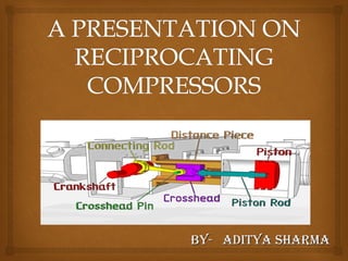
- 6. Different parts of Reciprocating compressor are listed below: Suction valve. Suction Chamber. Piston & Piston Rod. Cylinder. Discharge valve. Discharge Chamber. Reciprocating Compressor
- 7. For low speed compressors (upto 330 rpm) and medium speed compressors (330-600 rpm), pistons are usually made of CAST IRON. Upto 7” diameter cast iron pistons are made of solids. Those of more than 7” diameters are usually hollow (to reduce cost). Carbon pistons are sometimes used for compressing oxygen and other gases that must be kept free of lubricant. Piston
- 8. Generally, the piston rod is fastened to the piston by means of special nut that is prevented from unscrewing. The surface of the rod has suitable degree of finish designed to minimize wear on the sealing areas as much as possible. The piston is provided with grooves for piston rings and rider rings. PISTON ROD
- 10. Piston Rings
- 11. Piston Rings Piston rings provide a seal that prevents or minimizes leakage through piston and liner. Metal piston rings are made either in one piece, with a gap or in several segments. Gaps in the rings allow them to move out or expand as the compressor reaches operating temperature. Rings of heavy piston are sometimes given bronze, Babbitt or Teflon expanders or riders. Lubrication is a must for metallic rings. Teflon rings with Teflon rider bands are sometimes used to support the piston when the gas do not permit use of a lubricant.
- 12. Valves There are two valves namely suction and delivery valve. The valves are of automatic type. They open due to the effect of the differential pressure between cylinder and the suction or discharge chambers, and close due to the force of springs acting on the plates plus the differential pressure across the valves.
- 13. Principle of Operation Fig shows single-acting piston actions in the cylinder of a reciprocating compressor. The piston is driven by a crank shaft via a connecting rod. At the top of the cylinder are a suction valve and a discharge valve. A reciprocating compressor usually has two, three, four, or six cylinders in it. 13
- 14. 14 As the piston travels toward the bottom dead center, the volume of the cylinder increases and due to the pressure difference the suction valve is opened. The pressure inside the cylinder is slightly less than suction line pressure.So, the volume of the gas starts increasing as the piston moves towards BDC. So, the piston continues its motion towards BDC till the area above piston in the cylinder become full of fluid(gas) & then the suction valve gets closed.
- 15. Now when the crankshaft moves further and complete its revolution the piston also moves in opposite direction this time towards TDC. Now, again due to the Pressure difference between the delivery line and inside of the cylinder the delivery valves open in the delivery stroke. So, at point 3,the piston reaches the top dead center TDC. At top dead center, as the piston comes to a complete stop prior to reversing direction, the pressure across the valve is equal. So, the discharge valve is closed.
- 16. 16 At point 2, the pressure inside the cylinder has become slightly greater than discharge line pressure. This causes the valve opening allowing the gas to flow out of the cylinder. The volume continues to decrease toward point 3, maintaining a sufficient pressure difference across the discharge valve to hold it open.
- 17. 17 Now Again, As the piston moves towards BDC, the gas pressure inside the cylinder becomes less than the suction line pressure, so the suction valve opens again. The cycle then starts over again. The shape of the re-expansion line (Line 3-4) is dependent on the same compression exponent that determines the shape of the compression line.
- 18. The states of the refrigerant in a reciprocating compressor can be expressed by four lines on a PV diagram as shown in Fig
- 20. They are used to generate High pressurised air. They have one low pressure compressor and one high pressure compressor and in between them there is an INTERCOOLER. Firstly, air goes into low pressure compressor and compressed. Then this compressed air goes to INTERCOOLER(heat exchanger) where its temperature is decreased by Rejection of heat at Constant Pressure. Multi Stage(Two Stage) Reciprocating Compressor Work Saved
- 21. Then the air is passed to the high pressure compressor to get further compressed. Highly pressurized air is thus obtained from the delivery valve of high pressure compressor.
- 22. Reciprocating compressors are typically used where high compression ratios (ratio of discharge to suction pressures) are required per stage without high flow rates, and the process fluid is relatively dry. P.E.T bottling industries, gas filling stations usually use reciprocating compressors. 22 Application of compressors
- 23. Processing equipment, Oxygen Generators Oil Atomization use compressors of required capacity. 23