1. 1
____________________________ _______________________ __
FOR
Revit
____________________________ _________________________
SKILL LEVEL
Medium
____________________________ _________________________
ALSO REQUIRED
• Green Building Studio
• Your own Revit model (optional)
____________________________ _________________________
OBJECTIVES
• User Interface
• Plans
• Basic Families
• Quick Renders
____________________________ _________________________
TIME TO COMPLETE
2-3 Hours
____________________________ _________________________
RESOURCES
Lesson Files
https://www.facebook.com/groups/352022295146424/
Suggested Reading
• Autodesk Revit Architecture 2016 No Experience Required
- Eric Wing
____________________________ _________________________
WORKFLOW
Revit to Green Building Studio Online
A REVIT SESSION
Lesson 01A
MODELLING TO
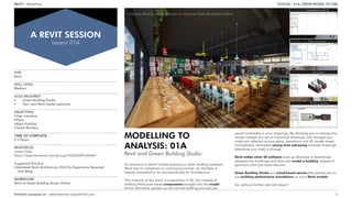
ANALYSIS: 01A
Revit and Green Building Studio
LESSON / 01A /FROM MODEL TO GBS
finished examples at / adambrennan.myportfolio.com
Example Work by Adam Brennan for Gourmet Rasta Modelled In Revit
REVIT / Modelling
So welcome to Revit! Unlike Autocad or other drafting software,
Revit has no crosshairs or command prompt, its interface is
heavily simplified in its use specifically for Architecture.
The majority of the work is undertaken in 2D, but instead of
drafting Revit puts these components straight into the model
which ultimately speeds up the normal drafting process you
would undertake in your drawings. By allowing you to change the
model instead of a set of individual drawings, any changes you
make are reflected across plans, elevations and 3D model views
immediately, ultimately saving time redrawing multiple drawings
whenever you make a change.
Revit unlike other 3D software such as Sketchup is specifically
designed for buildings and thus you model a building instead of
geometry that just looks like one.
Green Building Studio is a cloud-based service that allows you to
run building performance simulations on your Revit models.
So, without further ado let’s begin!
Part One: Introduction to the UI
Part Two: Views and Levels
Part Three: Using Types
Part Four: Finishing Touches
2. 2
NEW PROJECT AND USER INTERFACE
From the project screen start a new project file [1]. *please check
this is metric
The user interface of Revit has a ribbon a the top of the window
which is built up of a series of tabs containing panels [2].
Click the Wall button [2.1] and notice that Revit adds an additional
tab to the Ribbon with objects specific to your command and a
further Options Bar [2.2] for choices such as height and level.
The View Window [2] is where all your drafting takes place.
Navigate in 2D exactly the same way you would in Autocad (and
many more), with middle mouse button click and hold to pan and
scroll to zoom.
WELCOME TO REVIT
2D No More
FIGURE 2.1 The Ribbon like in Autocad can be used to access all commands and tools *two letter commands can also be used WA - wall
TabsIcons Panels
FIGURE 2.2 The User Interface of Revit is comparable to that of Microstation
2.2
2.1
21
3. 3
When you click on the Wall tool, a new set of commands appears,
this is the Properties interface, a set of specific commands which
is used in conjunction with the Modify Commands which are
generic and applicable to almost any situation [3].
INSTANCE PROPERTIES AND TYPE PROPERTIES
Revit uses two types of properties which control every
component of your building model.
Properties are available whenever you select an item or begin to
place a new one.
[3.1] Is the instance (element) properties and only affects the
selected item(s) or the new one created after setting up the
dialogue boxes. *By default this shows the View properties.
Click EditType to bring upType Properties
[3.2]Type properties are a key feature of Revit which makes work
drastically more efficient, but requires a little knowledge and
proper workflow to use well.
When a Type is edited it changes all components of the same
Type, so ensure they are named clearly.
ELEMENT/COMPONENT
Using the Properties Interface
This is the Type, when edited it affects all components of
the same Type (name)
3.23.1 3
4. 4
This should be made clear in the beginning, that if you start to
modifyType Properties without duplicating [4] the type first the
model can become affected in unintended ways.
DUPLICATE, DUPLICATE
Keep it Tidy
4
5. 5
Use the Options Bar to set the wall justification to Finish Face: Exterior using Location Line [5]
Finish Face: Exterior is one of the most common choices for Location Line (wall justification)
alongside Wall Centreline.
On the Options Bar ensure Chain is ticked to allow continuous wall drawing. The Draw Panel under
the ModifyTab has a number of different line drawing options much like any drafting software.
*Before starting any drawing get used to checking the Ribbon, Options Bar and Properties to ensure
you’re drawing what you want from the get go rather than going back to change properties after.
Using the Line option [5.1] draw a wall in the model space.
Click once to start drawing the wall somewhere in between the four elevation markers in the View
Window as shown in [5.2] and notice that the wall immediately begins to snap in a horizontal or
vertical alignment. Revit has no Ortho mode, but instead aligns to major increments 0, 90, 180, and
45 degrees.
DRAFTING 101
Lines? Just Draw A Wall
View Window
East Elevation Marker
North Elevation Marker
5.25.1
5
6. 6
Draw your first wall vertically upwards by moving the mouse
above the first point and typing 21000mm and hitting Enter. [6.1]
Once completed the next wall to be drawn automatically begins
and using Revit’s automatic wall snapping, set this to horizontal
by moving the mouse to the right of the end position and type in
22000mm. [6.2]
Follow the rest of the dimensions until you reach the point shown
in [6.3] then draw the wall manually by extending to the shown
point, notice that Revit creates an Inference Line (like many other
drafting software) which allows you to snap to a parallel endpoint
(aka Extension) and complete the perimeter wall.
Your end drawing should match the above [6], and here I’ve
annotated the External Wall Dimensions using Revit’s built-in
Dimensions, but you can quickly check these by selecting any wall
and viewing the Dynamic Dimensions that pop-up.
Try to become comfortable drawing a chain of walls like above
quickly as this will be the basis for most of your building drafting
in Revit.
PLANS
Making the Outline
66.1
6.2
6.3
7. 7
Most software have two types of selection, a Crossing-Window or Box Window.
Crossing-Windows [7.1] are drawn by dragging from right to left and selects anything within the
window and anything that crosses its boundary.
Box Windows [7.2] are drawn in the other direction from left to right and selects only objects that are
fully within the boundary.
This occurs across 3DS Max, Autocad, Microstation and many many more.
A NOTE ON SELECTION
Useful for Almost All Drafting Software
Crossing-Window Box Selection
7.27.1
8. 8
If you’ve ever used any drafting software you should already be familiar with all of the above tools
[8]. Although these work similarly to Autocad, there are some small differences.
Mirror -There are two types of Mirror, one where you pick a pre-existing axis and the other where you
draw a new axis from which you want your object to be Mirrored.
Here we are going to use the Mirror Draw Axis (DM) command and select the bottom perimeter wall
you just drew shown below and then hit enter.
The mirror command becomes active and begins searching for reference points to draw your new
axis from as you hover over things. For now, follow the line of the wall to the right of our selected
wall move up until the Dynamic Dimension shows up as 2200mm [8.1].
Click and then pull horizontally left drawing a new reference line [8.2] and then click to complete
[8.3].
MODIFY COMMANDS
Scale, Rotate, Mirror, Copy, Align, Offset, Trim, Split...
8.2
8.3
8.1
8
9. 9
Copy - Can be used to create a single copy or multiple and allows for more control than the basic
copy and paste method (Ctrl-C, Ctrl-V).
Activate the Copy Command (CO) [9] select the bottom left wall and hit Enter to activate as usual.
Make sure that multiple is checked for this exercise, and always check your Options Bar as usual.
The copy command like in Autocad requires you to select a Base Point [9.1] to copy the object from,
so select the Endpoint on this corner of the wall.
Move the copy along until 3500mm away from the endpoint until shows in the dimension and click to
complete [9.2].You can also use inference, to lock the copy command into a direction and type in the
distance.
Try to type in the distance to quickly make copies of the wall and match the screenshot [9.3].
COPY COMMAND
Copy Copy Copy
9.3
9.2
9.1
9
10. 10
Offset - Offset can be controlled by either a Graphical or Numerical value, but the Numerical setup is
the quickest and easiest when you know just how far you want to offset the new wall.
Activate the Offset Command (OF) [10] make sure you use Numerical and fill in 6000mm for the
Offset value.
Check Copy and then click on the left side of the wall [10.1].
Set another offset of 3000mm and do the same for the top wall.
OFFSET COMMAND
Quick and Simple
1
2
10 10.1
10.2
11. 11
Trim/Extend -This comes in three parts and is very similar to Autocad’s Fillet tool. UnlikeTrim and
Extend in Autocad these ave been rolled into one much easier to use tool.The trim tool here however,
by default, assumes you only want to trim two elements and join them together as this is the most
common function.To trim only a single element or multiple elements requires you to click one of the
two smaller icons in the interface.
Activate theTrim/Extend tool (TR) and select your first element for reference [11.1].
Then pick the second element you want to trim to, but ensure you pick on the side you wish to keep
and that’s it! [11.2]
[11.3] & [11.4] Show you how to use Single ElementTrim/Extend
[11.5] & [11.6] Show you how to use Multiple ElementTrim/Extend
The single reference element for both is highlighted in yellow.Try to make the end result match [11.6]
TRIM/EXTEND COMMAND
Fix Up Those Walls
11 11.1
11.2
13. 13
Split Element -This tool can be used to break-up walls and lines
into two separate elements and comes in handy when you want
to change the type of part of a wall for instance.
First activate the Split Element tool (SL) [12] and hover over this
part of the wall [12.1].The dimension appears and lets you know
the distance in relation to nearby reference points. Click to cut the
wall around the point shown.
Then select the walls shown in [12.2] and go to the properties
dropdown. Scroll down until you reach the Interior Partition wall
shown in [12.3] and select it.
Notice that all the walls change to match the selected Type on
the next page [12.4] this is Revit’s main feature and the ability to
changeType at any point speeds up the process of drafting.
Split the walls at the points shown [12.5] and then select the
inner segments and change the type to Curtain Wall Storefront
[12.6].
Use what you’ve learned so far withTrim/Extend and Properties to
clean up the drawing and match the final screenshot [12.7]
CHANGING TYPE
Speeding Up Your Work With Properties
12
12.1
12.2
12.3
15. 15
So, we’ve modelled a lot so far, well done, but we haven’t really
left the 2D drafting view to see the model we’ve been building all
along. It’s about time to check where we’re up to and actually view
our building model.
Double click the view named {3D} under 3D Views in the Project
Browser. Hey Presto!There it is!
Now navigating in 3D is much the same as 2D, but now we have
the ability to orbit.
Use middle mouse button and shift (the same as Autocad) to orbit
around your building model [13].
The View Cube [13] allows for greater control over the 3D View
and you can pick from a number of different orthographic views
top, left, right, axonometric etc.
*Revit’s 3D View is orthographic projection only and perspective
views requires you to set up a camera.
Whilst often people work in 2D experienced users spend a lot of
time viewing the building model in 3D when designing.
Now those walls are looking a little tall, so let’s fix that with our
next view!
VIEWS
And Changing Your Point Of...
Note: Changing properties
changes how the view plots
13.1
13.2
13.3
13
16. 16
Revit is designed specifically with architecture in mind unlike
Autocad which is used in a number of different disciplines.This
means that we can easily create architectural drawings such as
elevations and sections.
Double click the East Elevation under Elevations [14]. The
Properties Interface changes to show the View Properties for the
selected elevation only.
You’ll notice that there is an option for scale, this will change the
scale at which the view will actually plot at and changes the level
of detail for you accordingly.
The other thing you should see is the Levels in the centre of this
view. Levels are what every element in Revit aligns to. Let’s see
an example with walls.
Select the walls as shown [14.1], and filter this selection down to
walls only using the dropdown below the Type Selector [14.1].
Set theTop Constraint Property to: Up to Level 1 and click apply
[14.2].
All the tops of the walls are now constrained to Level 1 and will
vary to match whatever height value it is set to.
VIEWS
Elevations and Sections
*If your view doesn’t look like this and
appears to be showing the interior, the
elevation marker may be in the building
and can be moved out using the plan view.
14.1
14.2
14.3
14
17. 17
Under the ArchitectureTab, navigate to the Levels button [14.4] hover over the Level 1 marker to
bring up the inference (this just stops you having to align later) and move upwards until the reference
distance is 4000mm [14.5].
Click, and pull the line out and you’ve made Level 2 [14.6].
Notice that Level 2 is added to the Plan Views as a new view [14.6].This is how Revit works, creating
new levels as it would in a real building, adds a whole new floor plan which can be edited.
VIEWS 2
Elevations, Because It’s Essential Stuff
14.5
14.6
14.4
18. 18
So, we’ve got walls, but this house is far from comfy, without
floors or roof, we can assume this isn’t going to fare well in
performance analysis...
Let’s fix that. In 2D drafting in CAD the floor plate is implied by the
perimeter of your walls or a line, but in Revit we need this as an
element for the model with its own properties.
Return to Floor Plans - Level 0 and select Floor [15]. The Modify
Panel becomes active and the draw tools appear. Additionally the
Properties Panel shows us the properties of the floor we are about
to draw. For now let’s stick with the default and start drawing the
floor.
Check that the Level under constraints in the properties interface
is set to Level 0 [15.1].Then pick the Pick Walls drawing option
under Draw, this draws the floor aligned with the wall cores as
they should be and once created offsets it downwards.
Pick the most of the perimeter walls [15.2] for the floor, but you
will have to use theTrim/Extend tool to get a clean finish as the
wall cores vary. [15.3] Revit will not let you create a floor with an
“Open Sketch” so make sure to close or you will get a warning.
Hit theTick in the Modify Panel to complete the floor.
FLOORS
Not Just A Home Comfort
15.1
15.2
15.3
15
19. 19
Making a basic flat roof in Revit is easy as it follows exactly the
same process as floor with a couple of additions.
Go to Floor Plans Level 1 and pick Roof from the Build Panel [16].
In the Options Bar uncheck Defines Slope and set the overhang to
150mm [16.1].
*Defines slope can be used on specific lines to create a shaped
sloped roof
Draw the roof as you did with the floor previously, but make sure
to click on the External Face of the wall [16.2].
When the Sketch is closed complete the sketch and go back into
the 3D view. We’re looking a lot more complete now!
ROOVES
Gimme Shelter
16.1
16.2
16.3
16
20. 20
Often as a simple as a click away, Revit makes adding doors and windows simple.
Go to floor plan Level 0 and select the door tool (DR) under the architecture tab [17].
In the type selector choose the door with dimensions 1010 x 2110 as shown [17.1]
To place a door, hover over the where it is to be located and click to place. Use spacebar to flip the
direction of the door to get it in the correct orientation.
Place the door as shown in [17.2] and continue placing more doors until it matches [17.3] using
spacebar and hovering over the wall to place.
DOORS
Make Way
17.117 17.2
17.3
21. 21
Now lets get some windows in!
Go to floor plan Level 0 and select the window tool (WN) under the architecture tab [18].
In the type selector choose the window with dimensions 1360 x 1210mm as shown [18.1] we're
going to leave the sill height as default 900mm
As with the door to place a window, hover over the where it is to be located and click to place. Again
you can use spacebar to flip the direction of the window to get it in the correct orientation.
Note: as you should already be aware the interior sill of a window goes inside the building. Revit
does not work this out for you so place your window correctly by clicking on the exterior face.
Place the window as shown in [18.2] and continue placing more windows until it matches [18.3]
using spacebar and hovering over the wall (exterior) to place.
WINDOWS
Let There Be Light
18.118 18.2
18.3
22. 22
As mentioned previously Revit uses types to improve your
workflow and now we've got a building shell set up, let's delve in
these in more detail.
Let's begin with changing the type of a wall. Select the four walls
shown (using ctrl to add to the selection) and click the edit type
button [19].This brings up the Type Properties dialogue shown
[19.1], first change wrapping at ends to exterior, click preview and
then duplicate [19.1].
Rename the wall to Wall-Ext_25Pwk-125Ins-100LBlk-12P just
change the parts underlined.
Duplicating will prevent you overwriting an existing type and
unintentionally changing your model.
Then click Edit in the structure dialogue box. [19.1]
In the structure dialogue click on the Brick, Common material and
the small ellipsis to change the material [19.2]
This opens up the materials dialogue where you can change and
select the new materials. [19.3] These materials have structural
(physical) and thermal values beyond appearance only which
relate to real world characteristics for a BIM model.
TYPES
The Key to Revit
19.1
19.2
19.3
19
1
2
3
4
23. 23
19.4 19.5
19.6
Select Cladding,Vertical Ribbed and click ok [19.4].
Set the Cladding,Vertical Ribbed thickness to 25.0mm and increase the thickness of the Thermal/Air
Layer to 125.0mm [19.5].
Once that's completed hit ok and apply and watch as the model updates in all views.The overall wall
thickness in plans and sections adjusts, and the 3D view should update the material too [19.6].
Select the curtain wall [19.7] and set the properties as shown [19.8].
Finally using the move tool (MV) from before set Disjoin in the options bar and move the three
curtain walls back to align with the edge of the floor plate [19.9].
TYPES
Part 2
25. 25
20 20.1
20.2
Revit has a large amount of component types also known as Families provided with the basic
package, families encompass a large number of different objects from doors and windows to
furnishings, ducts, wall profiles and titleblocks for sheets [20].
Advanced Revit users will often edit these or create their own, and this will be taught to you in a later
session. For now, we'll learn how to load a Family in order to provide more options for door and
windows in the model.
Go to the Insert tab and click on the Load Family button [20.1].
Then navigate to the window shown in [20.2] and click open.
Right Click on one of the selected windows [20.2] to bring up an option to select all instances of that
family, and then use shift + click to deselect the three windows shown [20.3].
Set the type to the new Family [20.4] you loaded and go to the edit type dialogue setting a new
height for this window to 1810mm [20.5]. Try to follow the rest of the steps to make [20.9]
COMPONENT TYPES (FAMILIES)
The Smaller Stuff
28. 28
Finally let's change the doors for some more appropriate external door types using the same method
we used to change the window [21].
Congratulations!!
We're finished with Revit for now, the extended lesson will include importing into Green Building
Studio online and a more advanced class will teach you how to add sections, edit families and make
even more detailed models of your buildings.
COMPONENT TYPES (FAMILIES)
Put External Doors In
21 21.1
21.2
![2
NEW PROJECT AND USER INTERFACE
From the project screen start a new project file [1]. *please check
this is metric
The user interface of Revit has a ribbon a the top of the window
which is built up of a series of tabs containing panels [2].
Click the Wall button [2.1] and notice that Revit adds an additional
tab to the Ribbon with objects specific to your command and a
further Options Bar [2.2] for choices such as height and level.
The View Window [2] is where all your drafting takes place.
Navigate in 2D exactly the same way you would in Autocad (and
many more), with middle mouse button click and hold to pan and
scroll to zoom.
WELCOME TO REVIT
2D No More
FIGURE 2.1 The Ribbon like in Autocad can be used to access all commands and tools *two letter commands can also be used WA - wall
TabsIcons Panels
FIGURE 2.2 The User Interface of Revit is comparable to that of Microstation
2.2
2.1
21](data:image/gif;base64,R0lGODlhAQABAIAAAAAAAP///yH5BAEAAAAALAAAAAABAAEAAAIBRAA7)