
Empfohlen
Weitere ähnliche Inhalte
Was ist angesagt?
Was ist angesagt? (20)
Ähnlich wie Linac- A Practical Approach
Ähnlich wie Linac- A Practical Approach (20)
Kürzlich hochgeladen
Kürzlich hochgeladen (20)
Linac- A Practical Approach
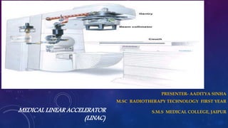
- 1. MEDICAL LINEAR ACCELERATOR (LINAC) PRESENTER- AADITYA SINHA M.SC RADIOTHERAPY TECHNOLOGY FIRST YEAR S.M.S MEDICAL COLLEGE, JAIPUR
- 2. OVERVIEW • To better understand about the functioning and usage of medical linear accelerator. • To be familiar with the basic used technology in LINAC.
- 3. WHAT IS A MEDICAL LINEAR ACCELERATOR ? • The linear accelerator is a device that uses high- frequency electromagnetic waves to accelerate charged particles such as electrons to high energies through a linear tube. • Electron trajectories are linear in the accelerator tube hence the name ‘LINEAR ACCELERATOR’. • • The high-energy electron beam itself can be used for treating superficial tumors, or it can be made to strike a target to produce x-rays for treating deep-seated tumors.
- 4. HISTORY OF MEDICAL LINEAR ACCELERATOR • 1952: Henry Kaplan and Edward Ginzton begin building a medical linear accelerator. • 1956: The first medical linear accelerator in the Western Hemisphere is installed at Stanford Hospital in San Francisco. • 1959: Stanford medical school and hospital move to the Palo Alto campus, bringing the medical linear accelerator. • 1962: Kaplan and Saul Rosenberg begin trials using the linear accelerator with chemotherapy to treat Hodgkin's disease, an approach that dramatically improves patient survival. • 1994: First use of the CyberKnife, invented at Stanford, which uses sophisticated computerized imaging to aim a narrow X-ray beam precisely. • 1997: Stanford pioneers the use of intensity-modulated radiation therapy, which combines precise imaging with linear accelerators that deliver hundreds of thin beams of radiation from any angle. • 2004: Implementation of four-dimensional radiotherapy, which accounts for the motion of breathing during imaging and radiation delivery. • Medical linear accelerators have become the backbone of Radiation Therapy for cancer worldwide.
- 5. HISTORY OF LINAC (CONTD.) • A 2-year-old boy suffering from a tumor in his eye, was the first to undergo X-ray treatment from a medical linear accelerator that was developed by Henry Kaplan with campus physicists. • • The treatment saved the child's sight and he lived the rest of his life with his vision intact. The first patient to receive radiation therapy from the medical linear accelerator at Stanford was a 2- year-old boy. Henry Kaplan (left), and head of radiologic physics Mitchell Weissbluth, the first physicist Kaplan hired, at the working end of the Stanford accelerator
- 6. GENERATION’S OF MEDICAL LINEAR ACCELERATOR • The first one was installed in Hammersmith in 1952. • In 1956 ,the first patient was treated at Stanford University in USA. • The LINAC had an 8-MV Xray beam with limited gantry motion. • These LINACs were large and bulky.
- 7. GENERATIONS OF MEDICAL LINEAR ACC. (CONTD.) Second Generation Third Generation The second generation was isocentric and could rotate 360o around the gantry axis. • They were built between 1962-1982. • They increased the accuracy and precision of Dose delivery • Better accelerator waveguides and bending magnet systems and more beam modifying accessories. • Wider range of energies , dose rates, field sizes and operating modes. • Higher reliability and computer driven.
- 8. Medical Linear Accelerator consist of :- 1) Electron injection system 2) Microwave system 3) Power supply system 4) Beam transport beam monitoring system 5) Auxiliary system 6) Safety interlock system 7) Computer controlled feedback system 8) Beam collimator/applicator system 9) Cooling system 10) Control console system
- 9. 10MV, 15MV
- 11. THE MAJOR COMPONENTS OF MEDICAL LINEAR ACCELERATOR • • Power Supply • • Modulator • • Magnetron Or Klystron • • Electron Gun • • Wave Guide system • • Accelerator Tube • • Bending Magnet • • Treatment Head • • Treatment table(Couch) • Treatment Console
- 12. Block Diagram Of Medical Linear Accelerator !!
- 13. MODULATOR AND POWER SUPPLY • This important component of the linear accelerator is usually located in the treatment room In some Units. • The Modulator cabinet contains three major Components. 1. Fan control (cooling the power-distribution system). 2. Auxiliary power distribution system (contains the emergency off button that shuts off the power to the treatment unit ). 3. Primary power-distribution system • A power supply provides direct current (DC) power to the modulator, which includes the pulse-forming network and a switch tube known as hydrogen thyratron. • High voltage pulses from the modulator section are flat-topped DC pulses of a few microseconds in duration. • These pulses are delivered to the magnetron or klystron and simultaneously to the electron gun.
- 14. MANGNETRON • The magnetron is a device that produces microwaves. • It is a high-power oscillator, generates microwave pulses of frequency of about ~3,000 MHz. • Magnetron is cylindrical construction consists of evacuated central cathode and an outer anode with resonant cavities machined out of a solid piece of copper. • The cathode is heated by an inner filament and the electrons are generated by thermionic emission. • Both the electron gun and the Magnetron are fed with High voltage power supply & short duration pulses in synchrony with the Modulated power supply system. • Typical high voltage pulse of about 50kVp is a few micro seconds long and is repeated a few hundred times per second. • Pulse repetition frequency (PRF) OR Pulse per second differs according to manufacturer but pulse width remains constant.(Pulses are of about 4μs duration & are delivered at a PRF of 250Hz.) • PRF or PPS determines the dose rate from a LINAC.
- 15. KLYSTRON • The Klystron is a microwave amplifier. It is driven by a low-power microwave oscillator. • The electrons produced by the cathode are accelerated by a negative pulse of voltage into buncher cavity which is energized by low-power microwaves. • The microwaves set up an alternating electric field across the cavity. • The velocity of the electrons is altered by the action of this electric field to a varying degree by a process known as velocity modulation.
- 16. • Electrons form bunches due to variation in velocity resulting in bunching of electrons as the velocity-modulated beam passes through a field-free space in the drift tube. • As the electron bunches arrive at the catcher cavity, they induce charges on the ends of the cavity and thereby generate a retarding electric field. • The electrons suffer deceleration, and by the principle of conservation of energy, the kinetic energy of electrons is converted into high-power microwaves.
- 17. GUN • It is responsible for producing electrons and injecting them into the accelerator structure . • Tungsten Mesh/coil produces a stray of electrons due to thermionic emission when voltage is applied in terms of “Filament current”. • The electron gun and the source are pulsed so that the high velocity electrons are injected into the accelerating waveguide at the same time as it is energized by the microwaves. • The number of electrons ejected depends upon the temperature of the filament. • The electron gun and waveguide system are evacuated to a low pressure to make the mean free path of electrons between atomic collisions long compared to path in the system.
- 18. WAVE GUIDE SYSTEM Accelerator Guide : Also called as the accelerator structure , mounted in the gantry: i) Horizontally (High-energy machines) ii) Vertically (low-energy machines ). • Microwave power (produced in the klystron) is transported to the accelerator structure, in which corrugations(wrinkle) are used to slow the waves. • Accelerating electrons tends to diverge, partly by the mutual coulomb repulsion and mainly by the radial component of electric field in waveguide structure. • Electrons are focused back to their path by the use of co-axial magnetic focusing field generated by the coaxial coils which are coaxial with accelerating waveguide.(Also called as steering coils)
- 19. TYPES OF WAVE GUIDE SYSTEM 1) Travelling waveguide system 2)Standing wave guide system Travelling waveguide system • Travelling wave guide structure require relatively longer accelerating waveguide. • Functionally, traveling wave structures require a terminating, or " dummy," load to absorb the residual power at the end of the structure, thus preventing a backward reflected wave.
- 20. Standing wave guide system • Standing wave guide structure helps in reducing the accelerating length due to option of side coupling cavities. • The standing wave structures provide maximum reflection of the waves at both ends of the structure so that the combination of forward and reverse traveling waves will give rise to stationary waves as the microwave power is coupled into the structure via side coupling cavities. • Such a design tends to be more efficient than the traveling wave designs since axial, beam transport cavities, and the side cavities can be independently optimized.
- 21. TREATMENT HEAD • Treatment head comprises of components that are designed to shape and monitor the treatment beam. Bending magnet: Shielding material: X-ray target: Primary collimator Beam flattening filter: Scattering foil: Beam monitoring devices: Secondary collimators: Field light:
- 22. BENDING MAGNET • The electrons exit the waveguide and from where electron beam is redirected towards the target, the electrons travel along a ‘Slalom’ path. • Three pairs of magnets on the either side of the Flay tube, cause the electron beam to bend through the turns of the Slalom. • This process not only positions the beam to strike the target, but also focuses the beam to a diameter of 1mm. • The design of the magnets enables them to focus theelectrons of slightly different energies on to the same point on the target .
- 23. • Shielding Material- The treatment head consists of a thick shell of high-density shielding material such as lead, tungsten, or lead-tungsten alloy. • Shielding material is used to avoid the unnecessary irradiation to the surroundings, patient as well as the radiation workers. • X-Ray Target- The pencil electron beam strikes on the x-ray target to produce photons. • X-ray target used is transmission type target .It used is mainly made of Tungsten due to its high atomic number(Z = 74) & High melting point 33700C.
- 24. • Primary collimator : The treatment beam is first collimated by a fixed primary collimator located immediately beyond the x-ray target. In the case of x-rays, the collimated beam then passes through the flattening filter. In the electron mode, the filter is moved out of the way. • Flattening filter: Modifies the narrow, nonuniform photon beam at the isocenter into a clinically useful beam through a combination of attenuation of the center of the beam and scatter into the periphery of the beam. • It is made up of lead, steel or copper.
- 25. • Scattering Foil: In the electron mode of linac operation, narrow pencil electron beam, about 3 mm in diameter., instead of striking the target, is made to strike an electron scattering foil to spread the beam as well as get a uniform electron fluence across the treatment field. • The scattering foil consists of a thin high-Z metallic foil (e.g., lead, tantalum) . • The thickness of the foil is such that most of the electrons are scattered instead of suffering bremsstrahlung. • Carrouselis a device in treatment head which helps in the movement of ’Flattening filters of different energies as well as Scattering foils’.
- 26. • Beam monitoring devices: The flattened x-ray beam or the electron beam is incident on the dose monitoring chambers. • The monitoring system are transmission type ion chambers or a single chamber with multiple plates. cylindrical thimble chambers have also been used in some LINAC’S. • The function of the ion chamber is to monitor dose rate, integrated dose, and field symmetry. • As the chambers are in a high-intensity radiation field and the beam is pulsed, the ion collection efficiency of the chambers should remain unchanged with changes in the dose rate. • Bias voltages in the range of 300 to 1,000 V are applied across the chamber electrodes, depending on the chamber design. • The monitor chambers in the treatment head are usually sealed so that their response is not influenced by temperature and pressure of the outside air. • Beam monitoring devices: The flattened x-ray beam or the electron beam is incident on the dose monitoring chambers. • The monitoring system are transmission type ion chambers or a single chamber with multiple plates. cylindrical thimble chambers have also been used in some LINAC’S
- 27. • Secondary collimators: The beam is further collimated by a continuously movable x- ray collimators. • This collimators consists of two pairs of lead of tungsten blocks (jaws} which provide a rectangular opening (from 0X0 to 40X40 cm2) projected at a standard distance such as 100 cm from the x-ray source. • The collimator blocks are constrained to move so that the block edge is always along a radial line passing through the x-ray source position. • Field light: The field size definition is provided by a light localizing system in the treatment head. • A combination of mirror and a light source located in the space between the chambers and the jaws projects a light beam as if emitting from the x-ray focal spot. • Thus the light field is congruent with the radiation field. allows accurate positioning of the radiation field in relationship to skim marks or other reference points.
- 28. FIELD LIGHT AND LASERS • Field Light : It is a Field localizing device, Used to display the position of the radiation field on the patient skin. • An high accuracy bulb is placed at 450 angle with the Mercury mirror placed in the path of the beam (Transmission type mirror) . • The light field size is in congruence with the radiation field size.Field size can be varied with the help of this Light field size) • Lasers: The accuracy of the laser guides in determining Isocenter position. • Isocenter is a virtual point where the central axis of Gantry, Collimator and couch meets. • 2 Side lasers, saggital and Ceiling lasers are mounted on walls of LINAC unit. • Tolerance of laser position is 2 mm
- 29. TREATMENT TABLE ( COUCH) • Treatment table (Couch) : Treatment table is a mechanically movable motor driven couch . • Patient is positioned over the treatment table according to the desired co- ordinates of planning. • Patient is immobilized using the Immobilization devices. • Treatment table can be moved Horizontal, Vertical as well as Rotational directions. • Hand Pendent: It contains all the control switches which can be used to access the movement of Gantry, Couch, Collimator jaws(Field size),SSD etc.,
- 30. COOLING SYSTEM • Heat dissipation in linear acceleratoris an important step in maintenance in large setup and heavy patient load in hospitals. • The x-rays produced are almost the 1 percent of the electron energy which is striking on the target. • Hence 99% of the energy is converted to heat. • This heat is needed to be cooled and that is achieved by the ‘Cooling system’. • Cooling system consists of ‘water chiller’ for cooling the water and water inlets and outlets to various parts of LINAC including X- ray target
- 31. RADIATION SAFETY (INTERLOCK SYSTEM) • Similar to treatment from radiation the Safety from radiation also plays an important role in Radiotherapy. • Various Interlocks are present in LINAC to avoid the mis-happens or wrong treatment to the patient. • Interlocks indicates the problem in particular device in the LINAC assembly and interlocking system helps in solving the particularly and easily. • Safety Interlocks include: 1) Last Man Out Switch(LMO) 2) Door interlock 3) Beam ON/OFF Key etc., • Emergency switches are provided at all the systems of an LINAC unit to completely turn Off the entire Unit with only single switch during emergency situations.