
Empfohlen
Weitere ähnliche Inhalte
Ähnlich wie MFG 240 - Manufacturing DesignFinal ProjectScope of Project.docx
Ähnlich wie MFG 240 - Manufacturing DesignFinal ProjectScope of Project.docx (20)
Mehr von ARIV4
Mehr von ARIV4 (20)
Kürzlich hochgeladen
Kürzlich hochgeladen (20)
MFG 240 - Manufacturing DesignFinal ProjectScope of Project.docx
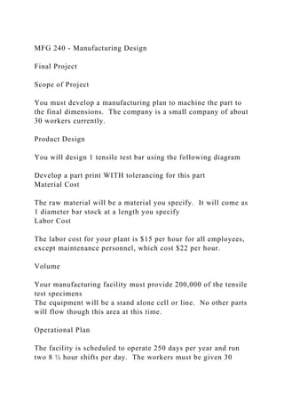
- 1. MFG 240 - Manufacturing Design Final Project Scope of Project You must develop a manufacturing plan to machine the part to the final dimensions. The company is a small company of about 30 workers currently. Product Design You will design 1 tensile test bar using the following diagram Develop a part print WITH tolerancing for this part Material Cost The raw material will be a material you specify. It will come as 1 diameter bar stock at a length you specify Labor Cost The labor cost for your plant is $15 per hour for all employees, except maintenance personnel, which cost $22 per hour. Volume Your manufacturing facility must provide 200,000 of the tensile test specimens The equipment will be a stand alone cell or line. No other parts will flow though this area at this time. Operational Plan The facility is scheduled to operate 250 days per year and run two 8 ½ hour shifts per day. The workers must be given 30
- 2. minutes for lunch and two 15-minute breaks. The product life cycle is expected to be 5 years or more. Reports Reports must be written using a word processor and spreadsheet when appropriate. All drawings must be completed using CAD. 1) Title Page 2) Table of Contents 3) Executive Summary 4) A written report detailing the manufacturing plan. The individual manufacturing deliverables must support all information presented in the manufacturing plan summary. i) Part prints (components plus assembly) ii) Initial investment required and projected cost per part iii) Conclusions, Recommendations 5) Manufacturing Plan Deliverables including all supporting data Manufacturing Plan Deliverables TAKT Time Calculations - TAKT is a German word for pace. TAKT time is the rate at which your customer requires the product. TAKT time defines the manufacturing line speed and the cycle time for the manufacturing operations. TAKT time is computed as: Available work time per day / Daily required demand (parts/day)
- 3. Design Cycle Time Calculations – Design cycle time is the cycle time at which you design your manufacturing operations after considering contractual breaks, setup time, planned maintenance, estimated downtime, reject rates, etc. All of the items above reduce your actual work time available per day and reduce the required cycle time. Each team must also consider the reject produced by the system and increase the required production to offset the loss. The team must report the manufacturing cells planned operational availability. Operational availability is the Planned operating time /Available work time. Process Plan Block Diagram – After reviewing the product prints, develop a process plan block diagram that represents the product flow through the various machines and processes. Include equipment, material handling, material flow, quality checks, repair loops, etc.. Equipment Sequence of Operations and Balance Chart – Develop a detailed step-by-step sequence of operations for each process or piece of equipment. Calculate the time required for each cut or step in the process. This document is required to determine if the operation can produce parts at the required rate. Do not forget to include operator load and unload times. When the sequence-of-operation charts are complete, use a graph to compare the cycle time of each process against the design cycle time for the line. The line should be balanced without any process above or well below the design cycle time of the line. Tooling – A list of all cutting tools with holders must be specified. Also include speeds and feeds. Be specific Fixture – A fixture concept must be specified. This does not have to be drawn Machining Equipment Specifications – Select the actual machines required to produce the parts including manufacture and model number. Make sure the machines can meet the
- 4. required horsepower, federates, and spindle speeds to make the cuts. Investigate the standard work holding device, turret and spindle supplied with the machine and make sure the selected tooling will mate appropriately. Consider the following factors: tool change time, MCU manufacturer, machine work envelope, machine footprint, cost, HP, etc…. Also specify the required chip removal system. Include any sales information you deem helpful on why you made your choice. Cost Estimate – Develop a detailed cost estimate of the initial investment required to purchase and install the manufacturing cell. Then determine the approximate unit cost of the product based on your manufacturing cell design. Include the following items in your calculations: a) Direct Material Cost – Include the initial purchase price of each component ($/unit). b) Direct Labor Cost – Calculate the total labor cost per shift divided by the number of parts produced per shift ($/unit). c) Burden Rate – The manufacturing facility has a burden rate of 250%. The burden rate includes such items as employee benefits, taxes, insurance, etc… Multiple the direct labor cost per unit (item b) by the burden rate to determine the burden rate cost per piece ($/unit). d) Depreciation Cost – Use straight-line depreciation to determine the impact of the initial investment. Assume the usable life of the equipment is 5 years with a salvage value of 15% at the end of the life span. Divide the initial cost minus the salvage value by five to determine the depreciation cost per year. Divide the annual depreciation cost by the annual volume to determine the cost per piece ($/unit) e) Add all of the above items together to determine the
- 5. estimated unit cost of the product. Research Theory, Design, and Methods Walden University © 2016 Laureate Education, Inc. Page 1 of 2 Purpose Statement Checklist Use the following criteria to evaluate an author’s purpose statement. Look for indications of the following: • Does the statement begin with signaling words? • Does the statement identify the research approach (quantitative, qualitative, or mixed)? • Does the statement clearly state the intent of the study? • Does the statement mention the participants? • Does the statement mention the research site? • Is the statement framed in a way that is consistent with the identified problem? If the study is qualitative, does the purpose statement do as follows? • Focus on a single phenomenon
- 6. • Use an action verb to convey how learning will take place • Use neutral, nondirectional language • Provide a general definition of the central phenomenon If the study is quantitative, does the purpose statement do as follows? • Identify the variables under study • Provide a general definition of each key variable • Use words that connect the variables • Identify a theory If the study is mixed methods, does the purpose statement do as follows? • Discuss the reason(s) for mixing both quantitative and qualitative data • Include the characteristics of a good qualitative purpose statement (as listed above) Research Theory, Design, and Methods Walden University © 2016 Laureate Education, Inc. Page 2 of 2 • Include the characteristics of a good quantitative purpose statement (as
- 7. listed above) • Indicate the specific method of collecting both quantitative and qualitative data 2 Table of Contents 1. Executive Summary……………………………………………………………… …….....1 2. Scope………………………………………………………………… …………………....1 3. Deliverables………………………………………………………… ………………….....2 a. TAKT Time Calculations…………………………………………………………2 b. Design Cycle Time Calculations………………………………………………….3 c. Process Plan Block Diagram……………………………………………………...4 d. Equipment Sequence of Operation and Balance Chart…………………………...4 e. Fixture………………………………………………………………… ……….....5 f. Machining Equipment Specifications…………………………………………….6 g. Material Handling, Containerization and Scheduling Plan ……………………...7 h. Quality
- 8. Plan…………………………………………………………………... …9 i. Manufacturing Cell Layout………………………………………………………10 j. Cost Estimate……………………………………………………………… …….11 4. Conclusion…………………………………………………………… ………………….11 5. References…………………………………………………………… ………………….12 1. 2. Executive Summary Tensile bar specimen, also known as “dog bone”, is a standardized cross-section used to in tensile testing to determine the tension of the material. The tensile bar has two shoulders to mate the grips in various machines. Tensile bars
- 9. have different shapes, typically round or square. The project is to produce round tensile bars that come in round bar stock in 1 inch diameter x 12 foot length. This project will focus on the tooling and the machining. It will also include a part design, a layout design, a cost estimate, a potential failure mode effect analysis, cycle time calculations, and cost estimate analysis. The part is to be produced at the lowest cost possible with high standards and high quality. Quality plans and techniques will be used in order to assure that the part will meet the criteria of our client. Material handling equipment will be used including storage racks, fork-lifts, conveyers, horizontal carousels, and waste containers. These equipment will assure high flow-efficiency. The project is also to calculate the TAKT time and the design cycle time. Time standards and time studies are used to calculate the total cycle time a part takes to be produced from raw material to a finish product. 3. Scope The scope of this project includes designing a facility that can efficiently run three main operation, facing, turning, and threading the tensile bar specimen. The plant will not have any tensile bar testing machines. The scope is only machining down the bar stock to the required material and inspecting the finished parts. Moreover, we are to design the tensile bar to demanded dimension, and specify tolerances. 4. Deliverables a. TAKT Time Calculations TAKT Time is the first element to be delivered. In order to
- 10. calculate the TAKT Time we first need to find the available time per work day. The available time per is calculated by multiplying the number of workers available per day by the operating hours. The annual demand of tensile bars is 200,000 units per year. The available time is calculated as the following: Available Time= (2 shifts/day) (8.5 hours/shift-1 hour break/shift) (30 workers per day) = 450 hours/day Therefore, the amount of available hours per day is 450 hours. Daily Demand = (200,000 parts/year) / (250 working days/year) = 800 parts/day TAKT Time= (450 hours/day) / (800 parts/day) = 0.56 hours/part → 33.75 min/part b. Design Cycle Time Calculations The cycle time includes many factors such as the machining time, setup time, handling time. From previous courses, Personal, Fatigue and Delay (PFD) are times that reduce the cycle time used in most manufacturing plants. Starting with machining time, the part needs three main operations to be produced. Facing both ends, reducing the radius, and threading the two ends of the tensile bar specimen. Using the formula below, the machining times are calculated in the table following it. tm= LπD / 12fV L= Ld + Ls Operation Time Calculations
- 11. Element Dimension Depth of Cut Length of Cut, Ld Safety Stock, Ls Length L Diameter D Velocity, V, fpm feed, f, (ipr) Minutes, tm 1. Face Ends 1.000 1.000 0.200 1/32 0.231 1.000 120 0.007
- 12. 0.072 2. Rough turn (Entire Part) 1.000 0.125 7.000 1/32 7.031 1.000 160 0.015 0.767 3. Finish turn (Entire Part) 0.875 0.125 7.000 1/32 7.031 0.875 160 0.007 1.438 4. Rough Turn (Middle) 0.750 0.125 2.000 1/32 2.031 0.750 160 0.015 0.166 5. Finish turn (Middle) 0.625 0.125 2.000 1/32
- 13. 2.031 0.625 160 0.007 0.297 6. Thread End 1 0.750 0.125 1.500 1/32 1.531 0.750 160 0.007 0.268 7. Thread End 2 0.750 0.125 1.500 1/32 1.531 0.750 160 0.007 0.268 Subtotal of machining times 3.009
- 14. · Machining Time: the machining time per part is 3.009. · Setup and Handling Time: setup and handling time is estimated to be 3.5 hours/shift → (7 hr/day) / (800 parts/day) = 5.25 min/part · PFD: Including downtimes of machines, under delays, PFD are estimated to be 12% of available time = 12% of 450 hours = 54 hours/ day → (54hrs *60 min)/ (200,000 parts/day)= .0162 min/ part · Maintenance: 40 hours per day = (4 hours * 60 min)/(200,000 parts/day)= .012 min per part · Quality Check is estimated to take 0.6 min/part · Packaging : 0.2 min/part Total Cycle Time per part = 3.009 min + 5.25 min + 0.0162 min + 0.012 min + 0.6 min + 0.2 = 9.0872 min per part c. Process Plan Block Diagram i. d. Equipment Sequence of Operation and Balance Chart i. ii. When comparing the actual time to the calculated TAKT time,
- 15. we find that the actual time is a lot less than the TAKT time. This means that at the current production rate with this available time, the plant will be able to produce 200,000 tensile bar specimens annually. In the graph i, the total calculated TAKT time is divided by the number of elements and compared to each actual element. Graph ii shows the total actual time compared to the total TAKT time. e. Fixture i. The fixture used to produce the tensile bar specimens is a turning fixture. The reason this type of fixture is selected is because the tensile bar is a round one. All operation can be done using the turning fixture including facing, turning, and threading. An adjustable fixture is to be used in order to accommodate the dimensions of the tensile bar specimen. f. Machining Equipment Specifications In order to calculate the horsepower required to perform the proper machining operations, the following equation is to be used: Using this equation, the following table demonstrates the hp required for each machine. No. Operation Ft (lbf) V (ft/min) HP 1 Facing 115 120 0.42
- 16. 2 Rough Turn 65 160 0.32 3 Finish Turn 65 160 0.32 4 Rough Turn 65 160 0.32 5 Finish Turn 65 160 0.32 6 Threading End 1 65 160 0.32 7 Threading End 2 65 160 0.32 The equipment to be used is a lathe machine from Alibaba with a HP of 2. Height of center
- 17. 8" Distance between centers 40" Spindle bore 2" Spindle nose D1-5 Spindle drive motor 2 hp overall pkg 760/840 kg Model Number CQ6240 g. Material Handling, Containerization and Scheduling Plan The plant will have four main material handling equipment in order to ensure the highest efficiency and material flow. 1. Stacking racks: to be used for storing bar stock once the raw material arrives at the manufacturing plant in the receiving/ storage department. 2. Conveyer belts: this material handling equipment is very efficient in delivering materials from one station to another. For our particular plant design and requirements, the conveyer belts are designed to have dividers and edges in order to prevent the round material from falling off the belt as it is moving. 3. Defects and scrap container: this material handling equipment is needed at every station to contain the waste chips produced from machining every tensile bar. Such container will also be at the inspection department in order to dispose the defective parts. The container will have wheels to be easily moved outside of the manufacturing plant and properly dispose the
- 18. material. 4. Horizontal carousel: this equipment is a storage equipment. For our plant, the carousels will be placed in the shipping department. Their design will consist of movable racks that can carry the packaged boxes of the finished and inspected parts that are ready to be shipped. 5. Fork-lift: Fork-lifts will be present at the receiving and shipping departments. Their duty is to transport material between the delivery trucks and the plant area. h. Quality Plan Tools: 1. GO/NO-GO gauge in a form of a nut to assure that the dimensions of the threads meet the criteria 2. Venier Calipers to measure the overall length and the length of the threaded part of the tensile bar specimen 3. Brinell hardness testing machine to measure the hardness of the material before it leaves the manufacturing plant i. Manufacturing Cell Layout
- 19. j. Cost Estimate Total Cost Per Part $45.83 5. Conclusion In conclusion, the determined cost is $45.83 per tensile bar specimen. The layout of the plant is designed in a U-shape with a conveyer that goes through each department from receiving to shipping. Material handling equipment are used to assure flow efficiency and time saving. TAKT time is calculated to 33.75 min/part which is less than the design cycle time, 9.1 min/part. The process plan is simply (receiving/storage, loading, facing, turning reduced section, turning shoulders, threading, inspection, packaging, and finally packaging/storage). The machines are selected based on the horsepower required. Tools along with feeds and speeds where also selected, they were also used in determining the design cycle time.
- 20. 6. Refrences a. Tompkins, James A., and John A. White. Facilities Planning. New York: Wiley, 1984. Print. b. Ostwald, Fillip F., and Timothy S. McLaren, PhD. Cost Analysis and Estimating for Engineering and Management. N.p.: Prentice Hall, 2003. Print. Balance Chart Actual Time Setup and Handling Face EndsRough Turn (Entire Part) Finish Turn (Entire Part) Rough Turn (Middle) Finish Turn (Middle) Thread End 1 Thread End 2 Maintenance PFD Quality Check Packaging5.25 7.1999999999999995E-2 0.76700000000000002 1.4379999999999999 0.16600000000000001 0.29699999999999999 0.26800000000000002 0.26800000000000002 1.2E-2 1.6199999999999999E-2 0.6 0.2 TAKT Time Setup and Handling Face EndsRough Turn (Entire Part) Finish Turn (Entire Part) Rough Turn (Middle) Finish Turn (Middle) Thread End 1 Thread End 2 Maintenance PFD Quality Check Packaging2.8125 2.8125 2.8125 2.8125 2.8125 2.8125 2.8125 2.8125 2.8125 2.8125 2.8125 2.8125 Element Time (Min)
- 21. Total Actual Time TAKT Time 9.3542000000000005 33.75