General Principles of Intellectual Property: Concepts of Intellectual Proper...
Lab view the switch mac address table lab - view the switch
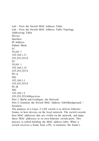
1. Lab - View the Switch MAC Address Table
Lab - View the Switch MAC Address Table Topology
Addressing Table
Device
Interface
IP Address
Subnet Mask
S1
VLAN 1
192.168.1.11
255.255.255.0
S2
VLAN 1
192.168.1.12
255.255.255.0
PC-A
NIC
192.168.1.1
255.255.255.0
PC-B
NIC
192.168.1.2
255.255.255.0Objectives
Part 1: Build and Configure the Network
Part 2: Examine the Switch MAC Address TableBackground /
Scenario
The purpose of a Layer 2 LAN switch is to deliver Ethernet
frames to host devices on the local network. The switch records
host MAC addresses that are visible on the network, and maps
those MAC addresses to its own Ethernet switch ports. This
process is called building the MAC address table. When a
switch receives a frame from a PC, it examines the frame’s
2. source and destination MAC addresses. The source MAC
address is recorded and mapped to the switch port from which it
arrived. Then the destination MAC address is looked up in the
MAC address table. If the destination MAC address is a known
address, then the frame is forwarded out of the corresponding
switch port associated with that MAC address. If the MAC
address is unknown, then the frame is broadcasted out of all
switch ports, except the one from which it came. It is important
to observe and understand the function of a switch and how it
delivers data on the network. The way a switch operates has
implications for network administrators whose job it is to
ensure secure and consistent network communication.
Switches are used to interconnect and deliver information to
computers on local area networks. Switches deliver Ethernet
frames to host devices identified by network interface card
MAC addresses.
In Part 1, you will build a multi-switch topology with a trunk
linking the two switches. In Part 2, you will ping various
devices and observe how the two switches build their MAC
address tables.
Note: The switches used are Cisco Catalyst 2960s with Cisco
IOS Release 15.2(2) (lanbasek9 image). Other switches and
Cisco IOS versions can be used. Depending on the model and
Cisco IOS version, the commands available and output produced
might vary from what is shown in the labs.
Note: Make sure that the switches have been erased and have no
startup configurations. If you are unsure contact your
instructor.Required Resources
2 Switches (Cisco 2960 with Cisco IOS Release 15.2(2)
lanbasek9 image or comparable)
2 PCs (Windows with terminal emulation program, such as Tera
Term)
Console cables to configure the Cisco IOS devices via the
console ports
Ethernet cables as shown in the topology
Note: The Fast Ethernet interfaces on Cisco 2960 switches are
3. autosensing and an Ethernet straight-through cable may be used
between switches S1 and S2. If using another model Cisco
switch, it may be necessary to use an Ethernet crossover
cable.Instructions
Build and Configure the NetworkCable the network according to
the topology.Configure PC hosts.Initialize and reload switches
as necessary.Configure basic settings for each switch.
Open configuration window
Configure device name as shown in the topology.
Configure IP address as listed in Addressing Table.
Assign cisco as the console and vty passwords.
Assign class as the privileged EXEC password.
Close configuration window
Examine the Switch MAC Address Table
A switch learns MAC addresses and builds the MAC address
table, as network devices initiate communication on the
network.Record network device MAC addresses.
Open a command prompt on PC-A and PC-B and type ipconfig
/all.
Open Windows command promptQuestion:
What are the Ethernet adapter physical addresses?
PC-A MAC Address:
Type your answers here.
PC-B MAC Address:
Type your answers here.
Close Windows command prompt
Console into switch S1 and S2 and type the show interface F0/1
command on each switch.
Open a configuration windowQuestions:
On the second line of command output, what is the hardware
addresses (or burned-in address [bia])?
S1 Fast Ethernet 0/1 MAC Address:
Type your answers here.
S2 Fast Ethernet 0/1 MAC Address:
4. Type your answers here.
Close a configuration windowDisplay the switch MAC address
table.
Console into switch S2 and view the MAC address table, both
before and after running network communication tests with
ping.
Establish a console connection to S2 and enter privileged EXEC
mode.
Open a configuration window
In privileged EXEC mode, type the show mac address-table
command and press Enter.
S2# show mac address-table
Even though there has been no network communication initiated
across the network (i.e., no use of ping), it is possible that the
switch has learned MAC addresses from its connection to the
PC and the other switch.Questions:
Are there any MAC addresses recorded in the MAC address
table?
Type your answers here.
What MAC addresses are recorded in the table? To which
switch ports are they mapped and to which devices do they
belong? Ignore MAC addresses that are mapped to the CPU.
Type your answers here.
If you had not previously recorded MAC addresses of network
devices in Step 1, how could you tell which devices the MAC
addresses belong to, using only the output from the show mac
address-table command? Does it work in all scenarios?
Type your answers here.Clear the S2 MAC address table and
display the MAC address table again.
In privileged EXEC mode, type the clear mac address-table
dynamic command and press Enter.
S2# clear mac address-table dynamic
Quickly type the show mac address-table command
again.Questions:
Does the MAC address table have any addresses in it for VLAN
1? Are there other MAC addresses listed?
5. Type your answers here.
Wait 10 seconds, type the show mac address-table command,
and press Enter. Are there new addresses in the MAC address
table?
Type your answers here.
Close a configuration windowFrom PC-B, ping the devices on
the network and observe the switch MAC address table.
From PC-B, open a command prompt and type arp -a.
Open a command promptQuestion:
Not including multicast or broadcast addresses, how many
device IP-to-MAC address pairs have been learned by ARP?
Type your answers here.
From the PC-B command prompt, ping PC-A, S1, and
S2.Question:
Did all devices have successful replies? If not, check your
cabling and IP configurations.
Type your answers here.
Close a command prompt
From a console connection to S2, enter the show mac address-
table command.
Open a configuration windowQuestion:
Has the switch added additional MAC addresses to the MAC
address table? If so, which addresses and devices?
Type your answers here.
Close a configuration window
Open a command prompt
From PC-B, open a command prompt and retype arp -
a.Question:
Does the PC-B ARP cache have additional entries for all
network devices that were sent pings?
Type your answers here.
Close a command promptReflection Question
On Ethernet networks, data is delivered to devices by their
MAC addresses. For this to happen, switches and PCs
dynamically build ARP caches and MAC address tables. With
only a few computers on the network this process seems fairly
6. easy. What might be some of the challenges on larger networks?
Type your answers here.
End of Document
2013 - 2019 Cisco and/or its affiliates. All rights reserved.
Cisco Public Page 1 of 11 www.netacad.com
2013 - 2019 Cisco and/or its affiliates. All rights reserved.
Cisco Public Page 11 of 11 www.netacad.com
Lab - View Network Device MAC AddressesLab - View
Network Device MAC AddressesTopology
Addressing Table
Device
Interface
IP Address
Subnet Mask
Default Gateway
S1
VLAN 1
192.168.1.2
255.255.255.0
N/A
PC-A
NIC
192.168.1.3
255.255.255.0
192.168.1.1Objectives
Part 1: Configure Devices and Verify Connectivity
Part 2: Display, Describe, and Analyze Ethernet MAC
AddressesBackground / Scenario
Every device on an Ethernet LAN is identified by a Layer 2
MAC address. This address is assigned by the manufacturer and
stored in the firmware of the NIC. This lab will explore and
analyze the components that make up a MAC address, and how
7. you can find this information on a switch and a PC.
You will cable the equipment as shown in the topology. You
will configure the switch and PC to match the addressing table.
You will verify your configurations by testing for network
connectivity.
After the devices have been configured and network
connectivity has been verified, you will use various commands
to retrieve information from the devices to answer questions
about your network equipment.
Note: The switches used are Cisco Catalyst 2960s with Cisco
IOS Release 15.2(2) (lanbasek9 image). Other switches and
Cisco IOS versions can be used. Depending on the model and
Cisco IOS version, the commands available and the output
produced might vary from what is shown in the labs.
Note: Make sure that the switches have been erased and have no
startup configurations. If you are unsure, ask your
instructor.Required Resources
1 Switch (Cisco 2960 with Cisco IOS Release 15.2(2) lanbasek9
image or comparable)
1 PC (Windows with a terminal emulation program, such as
Tera Term)
Console cable to configure the Cisco switch via the console
ports
Ethernet cables as shown in the topologyInstructions
Configure Devices and Verify Connectivity
In this part, you will set up the network topology and configure
basic settings, such as the interface IP addresses and device
name. For device name and address information, refer to the
Topology and Addressing Table.Cable the network as shown in
the topology.
Attach the devices shown in the topology and cable as
necessary.
Power on all the devices in the topology.Configure the IPv4
address for the PC.
Configure the IPv4 address, subnet mask, and default gateway
8. address for PC-A.
From the command prompt on PC-A, ping the switch address.
Open a Windows command promptQuestion:
Were the pings successful? Explain.
Type your answers here.
Close a Windows command promptConfigure basic settings for
the switch.
In this step, you will configure the device name and the IP
address, and disable DNS lookup on the switch.
Console into the switch and enter global configuration mode.
Open a configuration window.
Switch> enable
Switch# configure terminal
Enter configuration commands, one per line. End with CNTL/Z.
Switch(config)#
Assign a hostname to the switch based on the Addressing Table.
Switch(config)# hostname S1
Disable DNS lookup.
S1(config)# no ip domain-lookup
Configure and enable the SVI interface for VLAN 1.
S1(config)# interface vlan 1
S1(config-if)# ip address 192.168.1.2 255.255.255.0
S1(config-if)# no shutdown
S1(config-if)# end
*Mar 1 00:07:59.048: %SYS-5-CONFIG_I: Configured from
console by console
Close a configuration windowVerify network connectivity.
Open a Windows command prompt.
Ping the switch from PC-A.Question:
Were the pings successful?
Type your answers here.
Close a Windows command prompt.Display, Describe, and
Analyze Ethernet MAC Addresses
Every device on an Ethernet LAN has a MAC address that is
assigned by the manufacturer and stored in the firmware of the
NIC. Ethernet MAC addresses are 48-bits long. They are
9. displayed using six sets of hexadecimal digits that are usually
separated by dashes, colons, or periods. The following example
shows the same MAC address using the three different notation
methods:
00-05-9A-3C-78-00 00:05:9A:3C:78:00 0005.9A3C.7800
Note: MAC addresses are also called physical addresses,
hardware addresses, or Ethernet hardware addresses.
You will issue commands to display the MAC addresses on a PC
and a switch, and analyze the properties of each one.Analyze
the MAC address for the PC-A NIC.
Before you analyze the MAC address on PC-A, look at an
example from a different PC NIC. You can issue the ipconfig
/all command to view the MAC address of your NIC. An
example screen output is shown below. When using the ipconfig
/all command, notice that MAC addresses are referred to as
physical addresses. Reading the MAC address from left to right,
the first six hex digits refer to the vendor (manufacturer) of this
device. These first six hex digits (3 bytes) are also known as the
organizationally unique identifier (OUI). This 3-byte code is
assigned to the vendor by the IEEE organization.
To find the manufacturer, use the keywords IEEE OUI standards
to find an OUI lookup tool on the internet or navigate to
http://standards-oui.ieee.org/oui.txt to find the registered OUI
vendor codes. The last six digits are the NIC serial number
assigned by the manufacturer.
Using the output from the ipconfig /all command, answer the
following questions.
C:> ipconfig /all
<output omitted>
Ethernet adapter Ethernet:
Connection-specific DNS Suffix . :
Description . . . . . . . . . . . : Intel(R) 82577LM Gigabit
Network Connection
Physical Address. . . . . . . . . : 5C-26-0A-24-2A-60
DHCP Enabled. . . . . . . . . . . : Yes
10. Autoconfiguration Enabled . . . . : Yes
Link-local IPv6 Address . . . . . :
fe80::b875:731b:3c7b:c0b1%10(Preferred)
IPv4 Address. . . . . . . . . . . : 192.168.1.147(Preferred)
Subnet Mask . . . . . . . . . . . : 255.255.255.0
Lease Obtained. . . . . . . . . . : Friday, September 6, 2019
11:08:36 AM
Lease Expires . . . . . . . . . . : Saturday, September 7, 2019
11:08:36 AM
Default Gateway . . . . . . . . . : 192.168.1.1
<output omitted>Questions:
What is the OUI portion of the MAC address for this device?
Type your answers here.
What is the serial number portion of the MAC address for this
device?
Type your answers here.
Using the example above, find the name of the vendor that
manufactured this NIC.
Type your answers here.
From the command prompt on PC-A, issue the ipconfig /all
command and identify the OUI portion of the MAC address for
the NIC of PC-A.
Type your answers here.
Identify the serial number portion of the MAC address for the
NIC of PC-A.
Type your answers here.
Identify the name of the vendor that manufactured the NIC of
PC-A.
Type your answers here.Analyze the MAC address for the S1
F0/6 interface.
You can use a variety of commands to display MAC addresses
on the switch.
Console into S1 and use the show interfaces vlan 1 command to
find the MAC address information. A sample is shown below.
Use output generated by your switch to answer the questions.
Open a configuration window
11. S1# show interfaces vlan 1
Vlan1 is up, line protocol is up
Hardware is EtherSVI, address is 001b.0c6d.8f40 (bia
001b.0c6d.8f40)
Internet address is 192.168.1.2/24
MTU 1500 bytes, BW 1000000 Kbit/sec, DLY 10 usec,
reliability 255/255, txload 1/255, rxload 1/255
Encapsulation ARPA, loopback not set
Keepalive not supported
ARP type: ARPA, ARP Timeout 04:00:00
Last input never, output 00:14:51, output hang never
Last clearing of "show interface" counters never
Input queue: 0/75/0/0 (size/max/drops/flushes); Total output
drops: 0
Queueing strategy: fifo
Output queue: 0/40 (size/max)
5 minute input rate 0 bits/sec, 0 packets/sec
5 minute output rate 0 bits/sec, 0 packets/sec
0 packets input, 0 bytes, 0 no buffer
Received 0 broadcasts (0 IP multicasts)
0 runts, 0 giants, 0 throttles
0 input errors, 0 CRC, 0 frame, 0 overrun, 0 ignored
34 packets output, 11119 bytes, 0 underruns
0 output errors, 2 interface resets
0 unknown protocol drops
0 output buffer failures, 0 output buffers swapped
outQuestion:
What is the MAC address for VLAN 1 on S1?
Type your answers here.
What is the MAC serial number for VLAN 1?
Type your answers here.
Type your answers here.
What does bia stand for?
Type your answers here.
Why does the output show the same MAC address twice?
Type your answers here.
12. Another way to display the MAC address on the switch is to use
the show arp command. Use the show arp command to display
MAC address information. This command maps the Layer 2
address to its corresponding Layer 3 address. A sample is shown
below. Use output generated by your switch to answer the
questions.
S1# show arp
Protocol Address Age (min) Hardware Addr Type
Interface
Internet 192.168.1.2 - 001b.0c6d.8f40 ARPA Vlan1
Internet 192.168.1.3 0 5c26.0a24.2a60 ARPA Vlan1
What Layer 2 addresses are displayed on S1?
Type your answers here.
What Layer 3 addresses are displayed on S1?
Type your answers here.View the MAC addresses on the switch.
Issue the show mac address-table command on S1. A sample is
shown below. Use output generated by your switch to answer
the questions.
S1# showmac address-table
Mac Address Table
-------------------------------------------
Vlan Mac Address Type Ports
---- ----------- -------- -----
All 0100.0ccc.cccc STATIC CPU
All 0100.0ccc.cccd STATIC CPU
All 0180.c200.0000 STATIC CPU
All 0180.c200.0001 STATIC CPU
All 0180.c200.0002 STATIC CPU
All 0180.c200.0003 STATIC CPU
All 0180.c200.0004 STATIC CPU
All 0180.c200.0005 STATIC CPU
All 0180.c200.0006 STATIC CPU
All 0180.c200.0007 STATIC CPU
All 0180.c200.0008 STATIC CPU
All 0180.c200.0009 STATIC CPU
13. All 0180.c200.000a STATIC CPU
All 0180.c200.000b STATIC CPU
All 0180.c200.000c STATIC CPU
All 0180.c200.000d STATIC CPU
All 0180.c200.000e STATIC CPU
All 0180.c200.000f STATIC CPU
All 0180.c200.0010 STATIC CPU
All ffff.ffff.ffff STATIC CPU
1 5c26.0a24.2a60 DYNAMIC Fa0/6
Total Mac Addresses for this criterion: 21Question:
Did the switch display the MAC address of PC-A? If you
answered yes, what port was it on?
Type your answers here.Reflection QuestionsCan you have
broadcasts at the Layer 2 level? If so, what would the MAC
address be?
Type your answers here.
Why would you need to know the MAC address of a device?
Type your answers here.
End of Document
2013 - 2019 Cisco and/or its affiliates. All rights reserved.
Cisco Public Page 1 of 8 www.netacad.com
2013 - 2019 Cisco and/or its affiliates. All rights reserved.
Cisco Public Page 8 of 8 www.netacad.com