SlideShare ist ein Scribd-Unternehmen logo
1 von 457
Downloaden Sie, um offline zu lesen
From page 22-32
I
Check for continuity between the
each wires and body ground.

Repair any short in wire(s) between the recirc. motor and control unit.

Is there continuity?
NO

Test the recirculation control motor at the blower (page 22-89).

NO
Is the motor OK?

Replace the motor.

YES

Substitute a known-good control
unit and recheck. If symptomlindi-

/;;t$;ac!gcooenstr~;gfirwlace

the

LT

RECIRCULATIO
CONTROL MOTOR

22-33
vnx.su
Troubleshooting
- Vent Door Control Motor
Self-diagnosis indicator light I comes on: Indicates a problem in the vent door control motor circuit. Use a digital
multimeter (KS-AHM32-03) to check it.
The vent door control motor regulates the vent door according to output from the control unit.
Problem in the vent door control

I

No.5

Turn the ignition switch OFF.

Make sure all wires in the vent
door control motor connector are
securely attached. Make sure the
linkage is free of obstructions.

Remove the climate control unit
(page 22-84). Leave the wire
connected.
I

Turn the ignition switch ON.
Set the temperature control dial at
TEMP display 18, then measure
battery voltage between No.5 terminal and body ground when
turning temperature control dial at
TEMP display 32. After, measure
battery voltage between No. 19
terminal and body ground when
turning temperature control dial at
TEMP display 18.

No:1 1

I

I

Substitute a known-good control
unit and recheck. If symptom/indi<T* h
~~;a~~;,~.v;q;raplace
t
e

To page 22-35

22-34
vnx.su

Fjo.14
(From page 22-34)
J
Turn the ignition switch OFF.

Disconnect the 6-P connector
from the vent door control motor.
YEUBLK

I

GRNl
RED

Turn the ignition switch ON.
Set the temperature control dial at
TEMP display 18, then measure
battery voltage between the
YEL/BLK terminal and body
ground when turning the temperature control dial at TEMP display
32.
After, measure battery voltage
between the YEL/BLU terminal
and body ground when turning
the temperature control dial at
TEMP display 18.

Is there battery voltage?
YES

BLKlGRN

YELlWHT

R e p a i r open in YEL/BLK or
YELlBLU wires between the vent
door control motor and control
unit.

Turn the ignition switch OFF.
Disconnect the 14-P connector
from the control unit.

Check for continuity between
YEL/BLK or YEL/BLU terminals
and body grond.

Is there continuitv?

Reoair short in the YELlBLK or
YELlBLU wires between the vent
1 tz control motor and control

1 Reconnect the 1,4Pconnector.
]

To page 22-36

(cont’d)

22-35
vnx.su
Troubleshooting
- Vent Door Control Motor (cont’d)
From page 22-35

From the back of the 14-P connector at the control unit,
measure voltage between the
No. 11 and body ground.

Substitute a known-good control
unit and recheck. If symptomlindiYES

I

Measure voltage between the
GRN/RED terminal and body
ground.

I

I

Is there approx. 5V

NO

I

Repair open in the GRNlRED wire
between the vent door control
motor and control unit.

YES

Turn the ignition switch OFF.

Disconnect the 14-P connector

p+q

Check each wires for continuity:
l YEUWHT wire
l BLKIGRN wire

<*e ffffKLE2xz:

vent door control motor and con-

To page 22-37

22-36
vnx.su
From page 22-36

Check for continuity between the
GRN/RED, YEL/WHT or BLK/GRN
wire(s) and body ground.

NO

Repair short in the GRNIRED,
YELANHT or BLKlGRN wire(s) between the vent door control motor and control unit.

Test the vent door control motor
at the heater (page 22-W.

Replace the vent door control
motor.
YES

Substitute a known-good control
unit and recheck. If symptom/indication goes away, replace the
original control unit.

22-37
vnx.su
Troubleshooting
- Power Circuits to A/C Control Unit
First, check for blown No.33 (7.5A)

and No.4 (15A) fuses.

No heater and AIC in either manu-

Remove the climate control unit
(page 22-84).

Disconnect the 30-P connector
from the climate control unit.

Turn the ignition switch ON.

Measure voltage between the
No.30 (WHT/YEL) terminal and
body ground.

Repair open in WHTlYEL (No.301
wire between the control unit and
No.33 (7.5 A) fuse.
YES

Measure voltage between:
l No.28 (YEL/BLK)
terminal and
body ground.
l No.27 (YEL/BLK)
terminal and
body ground.

,


Is there battery voltage?
I
YES

NO
I

Repair open in YELlBLK (No.27 or
No.281 wire between the control
unit and No.4 (15A) fuse.

To page 22-39

22-38
vnx.su

I
From page 22-38

Check for continuity between:
l No.25 (8LK) and body ground.
l No.24 (BLK) and body ground.

Is there continuity?

NO

Repair open BLK (No.24 or No.251
wire between the control unit and
body ground. If wires are OK,
check for poor ground at G401.

Substitute a known-good control
unit and recheck. If symptomlindi-

22-39
vnx.su
Troubleshooting
-

Blower Motor
SUB RELAY
First, check for blown No.28(30A)

and No.4(15A)

fuse

Blower motor does not run at all.
I

j
r ~mho;m;;m;;vethe

cover from sub kelay box A and re-

I

Turn the ignition switch ON.

,
Measure voltage between the
BLU/WHT wire terminal (+ ) and
body ground (- 1.

NO,

Is there battery voltage?
YES

Measure voltage between the
YELlBLK wire terminal (+I and
body ground (- 1.

1

Is there battery voltage?

>

I


-T

<’

Repair open in BLWVHT wire between the No.28 (30AI fuse and
blower relay.

YES

To page 22-41

22-40

vnx.su
From page 22-40

r

1

Test the blower relay: Connect
battery power to relay terminal C,
then connect terminal D to body
ground. There should be continuity between terminals A and B
with power connected, no continuity with power disconnected.

Replace the blower relay.
YES

Check for continuity between the
BLK wire terminal and body
ground

Repair open in BLK wire between
the blower relay and body
ground. If wire is OK, check for
poor ground at 0301.

YES

Turn the ignition switch OFF.

I

Reinstall the blower relay.

Disconnect the 2-P connector
from the blower motor.
BLOWER MOTOR
CONNECTOR
Turn the ignition switch ON.

I

To page 22-42

(cont’d)

22-41

vnx.su
Troubleshooting
Blower Motor (cont’d)

BLOWER MOTOR
CONNECTOR

Measure voltage between the
BLURED wire terminal (+I and
body ground (- 1.

Is there battery voltage?

BLUIRED

BLKIBLU

From page 22-41

Repair open in BLUlRED wire between blower motor and blower
relay

YES

Inspect the blower motor.

Does the blower motor run?

NOTE: Connect the battery power
to the BLWRED wire terminal and
connect the BLK/BLU wire terminal to body ground. The blower
motor should runs.

Replace the blower motor.

I

YES

; :;ntx?mi;;~h

OFF.
SUB RELAY

Reconnect the connector to the

22-42
vnx.su

f. _

e
From page 22-42

rGizz+

NO

Does the blower motor run?

Repair open in BLKIBLU wire between blower motor and blower
high relay.

YES
Turn the ignition switch OFF.

1
the BLK/BLU wire terminal and

1 Turn the ignitio; switch ON.

Repair open in BLK wire between

1 ~!t~zLJL,,~;~~
Measure voltage between the
YEL/BLK wire (+) terminal and
body ground.

Repair open in YELIBLK wire between ignition switch and blower high relay.
YES
To page 22-44

‘j

(cont’d)

22-43
vnx.su
Troubleshooting
. Blower Motor kont’d)
From page 22-43

Test the blower high relay: Connect battery power to relay terminal C, then connect terminal D to
body ground. There should be
continuity between terminals A
and 6 with power connected, no
continuity with power disconnected.

Replace the blower high relay.
YES

I i Turn the ignitio; switch OFF.

#

Reinstall the blower high relay.

Remove the climate control unit
(page 22-84).

No.1 2 (ORNIWHT)

e

Disconnect the 30-P connector
from the climate control unit.

Connect a jumper wire between
the ORN/WHT wire terminal and
body ground.

Turn the ignition switch ON.

To page 22-45

a
vnx.su
From page 22-44

Repair open in ORNMfHT wire between blower high relay and climate control unit.
Substitute a known-good control
unit and recheck. If symptom/indication goes away, replace the
original control unit.

a

a
22-45
vnx.su
Troubleshooting
- Blower Speed Controls

Blower motor speed does not
change.

LT GRNlBLK

Open the hood disconnect the 3-P
power transistor connector from
the blower harness connector.

Connect a voltmeter between the

YES

Turn the FAN switch to the middle of its range.

To

v
B

To page 22-47

22-46
vnx.su
From page 22-46

V
B

Connect a jumper wire between
the BLK/BLU wire terminal and the
BLK wire terminal.

BLKIBLU

1
S e e troubleshooting,

BLUlRED

page

YES
I

I

Disconnect the 30-P connector
from the control unit and the 2-P
connector from the blower motor.
I
Check for continuity
BLK/BLU wire.

in

the

NO
Is there continuity?
1YES

Repar open in the
BLK/BLU wire between
the blower motor and
control unit.

Check for continuity between the
BLK/BLU terminal and body
ground.
No.22 (BLKIBLU)

Is there continuity?
NO

Repair short in the
BLKlBLU wire between
the blower motor and
control unit.

Replace the power transistor.

(dont’d)

22-47
vnx.su
Troubleshooting
- Blower Speed Controls (cont’d)

From page 22-46

Remove the climate control unit
(page 22-841.

‘...I
Disconnect the 30-P connector

Check for continuity in the LT
GRN/BLK wire.
I

I

Is there continuity?

NO

Repair open in the LT GRNlBLK
wire between the power transistor and control unit.

YES
Check for continuity between the
No.8 (LT GRN/BLK) wire terminal
and body ground.

1NO


Substitute a known-good control
unit and recheck. If symptomlindication goes away, replace the
original control unit.

vnx.su
22-49
vnx.su
Troubleshooting
A/C System
First, check for blown fuses: NO. 4 (15 A), No. 36 (10 A), No. 37 (10 A), No. 21 (10 A).

AK system does not work (cornpressor and condenser fans).

Remove the climate control unit
(page 22-84).

Disconnect the 30-P connector
from climate control unit.

Turn the ignition switch ON.

I
1

Measure voltage between the
No. 13 (GRY/BLK) terminal (+ )
and body ground I-).

NO

To

paw

I

Is there battery voltage?

Repair open in one of the two BLK
wires between the climate control
unit and body ground. If the wires
are OK, check for a poor ground
at 6401.

22-51

YES

Check for continuity between;
l No.25 (BLK) terminal and body
ground.
l No.24 (BLK) terminal and body
ground.

YES

/

Substitute a known-good climate
control unit and recheck. If symptomlindication goes away,
replace original control unit.

22-50
vnx.su
From page 22-50

1

1 Turn the ignition switch OFF.

I

Disconnect the 12-P connector
from cooling fan control unit.

I

Substitute a known-good cooling

replace the original control unit.

22-51
vnx.su
-Condenser Fan
First, check for blown fuses: NO. 4 (15 A), No.36 (10 A), No. 37 (10 A).

One or both condenser fans does

1
z:~:~:::::;e /
cover from sub ;elay

/

box A and re-

Using a jumper wire, connect the
VV-l~T/~RNwireterminaltobody

l Do both condenser fans run?

/

L--

To page 22-55

YES
Connect a jumper wire between
the WHT/GRN wire terminal and
ELK wire terminal.

Do both condenser fans run?
YES
Turn the ignition switch ON.

To page 22-53

22-52
vnx.su
From page 22-52

Measure the voltage between the
YEL/BLK wire terminal (+) and
body ground (- 1.

NO

I

YES

Repair open in the YELlBLK wire
between the No. 4 fuse (15 A)
and condenser fan relay.

Test the condenser fan relay:
Connect battery power to relay
terminal C, then connect terminal
D to body ground. There should
be continuity between terminals
A and B with power connected,
no continuity with power disconnected.

Replace the condenser fan relay.

Turn the ignition switch OFF, and
reinstall the condenser fan relay.

Disconnect the 12-P connector
from the cooling fan control unit.

Turn the ignition switch ON.

To page 22-54

(cont’d)

22-53
vnx.su
Troubleshooting
- Condenser (cont’d)
From page 22-53

Measure voltage between the
ORN/BLU terminal (+) and body
ground t-1.

NO

Is there battery voltage?

,

I

Repair open in the ORNlBLU wire
between the condenser fan relay
and cooling fan control unit.

fan control unit and recheck.
If symptom/indication goes away.
replace the original control unit.

22-54

vnx.su
V

From page 22-52

Right side: WHT
Left side: WHTIBL

A

Disconnect the 2-P connector
from inoperative condenser
fan(s).

I

I

Measure voltage:
Right fan: WHT wire terminal
and body ground.
Left fan: WHT/BLU wire terminal and body ground.

I”.
Is there battery voltage at terYES

Repair open in WHT wire between
the No. 37 fuse (10 A) and the
right fan, or in the WHTIBLU wire
between the No. 36 fuse (IOA)
and the left fan.

Test both condenser fan motors.
Connect battery power to the
WHT and WHT/BLU wire terminals and connect the WHT/GRN
terminal to body ground. Both
fans should run.

NO
Does the fan motor(s) OK?
I
YES

r
between the condenser fan motor

Replace the faulty fan motor.

1

22-55
vnx.su
Troubleshooting
- A/C Compressor
:irst, check for blown fuses: No. 21 (IO A), No. 4 (15 A).
Compressor clutch does not engage. When AIC is turned on with
engine running.

Remove the compressor clutch relay from sub relay box A.

c

/

Is there battery voltage?

..NW


YES

,
Repair open in the PNKlORN wire
between the No. 21 (IO A) fuse
and compressor clutch relay.

I
Turn the ignition switch ON.

Measure voltage between the
YEL/BLK wire terminal (+I and
body ground (- ).

NO
’

Is there battery voltage?

Repair open in the YELlBLK wire
between the No. 4 (16 A) fuse
and compressor clutch relay.

YES

To page 22-57

22-56
vnx.su
From page 22-56

Test the compressor clutch
relay: Connect battery power to
relay terminal C, then connect terminal D to body ground. There
should be continuity between terminals A and Et with power connected, no power with power
disconnected.

NO
Is the relay OK?
YES
I
1 Turn the ignition switch OFF.

Remstall

I

Replace the compressor clutch
relav.

I

I
1

the compressor clutch

p

Remove the panel from behind the
passenger seat. Disconnect the 4
connectors from PGM-FI-ECU.
Connect teh ECU test harness
connectors to the ECU.

Turn the ignition switch ON.

I--+

ECU TEST HARNESS

Measure battery voltage between

NO
Is there battery voltage?

Repair open in the REDlBLU wire
between the compressor clutch
relay and PGM-FI-ECU.

YES

To page 22-58

(cont’d)

22-57
vnx.su
Troubleshooting
- A/C Compressor (cont’d)
From page 22-57
ECU

Start the engine and connect a
jumper wire between test harness
terminal Al 5 and body ground.

ECU TEST HARNESS

Al5

I

Does compressor clutch engage?

I
Turn the ignition switch OFF.

YES

B
L7

Using a jumper wire, connect C3
test harness terminal to body
ground.

To page 22-61

NO

Does compressor clutch engage?

Substitute a known-good PGM-FIECU and recheck. If symptomiindication goes away, replace the
original ECU.

YES
Turn the ignition switch OFF.

?

c3

I

A

To page 22-59

22-58

vnx.su

I
From page 22-58

Disconnect the test harness, and
reconnect the connectors to the

BRNlBLK

Disconnect the 4-P connector
from the pressure switch.

BLK

YES

Check refrigerant pressure. If
pressure good, replace AIC pressure switch.

NO

Repair open in the BLK wire between the pressure switch and
body ground or poor ground
(0302).

Does compressor clutch engage?
NO
Turn the ignition switch OFF.

I

Check for continuity between the
8LK wire terminal and body
ground.

Is there continuity?
YES

To page 22-60

(cont’d)

22-59
vnx.su
Troubleshooting
I A/C Compressor (cont’d)
From page 22-59

connector from the cooling fan

Check for continuity of BRN/BLK
wire between the cooling fan con/ t r o l u n i t a n d prey” s w i t c h .

Repair open in the BRNIBLK wire
between the cooling fan control
unit and pressure switch.

YES

11 Start the enginei

NO
Does compressor clutch engage
YES

Repair open in the BLWBLK wire
between PGM-F&ECU and cooling
fan control unit.

Substitute a known-good cooling
symptom/indication goes away.
replace the original control unit.

22-60
vnx.su
From page 22-58
B

?
Disconnect the connector from
compressor.

Turn the ignition switch ON.

g
1 r o u n d

t-1.

RED

Repair open in the RED wire between the compressor clutch relay and compressor.

Is there battery voltage?
YES
( Replace the compressor clutch.

1

22-6 1
vnx.su
Blower

22-62
vnx.su
-Replacement
1.

2.

Remove the spare tire (refer to Owner’s manual).
Remove the spare tire holder.

4.

* CORROSION RESISTANT BOLT

Remove the sub relay box A and the water drair
duct. Disconnect the connectors from the blower
motor, power transistor and recirculation contra
motor.
Q CORROSION RESISTANT BOLT

4 6 mm bolt
I?r 6 mm bolt

DUCT
BLOWER,
POWER TRANSISTOR,
and RECIRC. MOTOR
CONNECTORS
* 6 mm bolt-

5.

0

Remove the blower mounting bolts, then remove
the blower.
~2 CORROSION RESISTANT BOLT

3.

Disconnect the battery cables, loosen the hold-down
bracket nuts, and remove the hold-down bracket.
Then, remove the battery.

BATTERY

ab

6.

Install the blower in the reverse order of removal,
then make sure it runs and doesn’t leak any air.

BRACKET

22-63
vnx.su
Recirculation Control Motor
- Replacement
1.
2.

4.

Remove the blower (previous page).
Remove the recirculation control motor cover from
the blower (3 screws).

REClkCULATlON
CONTROL MOTOR COVER

3.

Remove the recirculation control motor (I connector and 3 screws).

RECIRCULATION
CONTROL MOTOR

L

22-64

vnx.su

Install the recirculation control motor in the reverse
order of removal. Apply battery voltage (page 22-89)
and watch the door movement.
Make sure that the recirculation door moves smoothly without binding.
Make sure the motor doesn’t pull the door too far.
A/C Service Tips and Precautions
1.
2.
3.
4.
5.
6.

Always disconnect the negative cable from the battery whenever replacing air conditioner parts.
Keep moisture and dust out of the system. When disconnecting any lines, plug or cap the fittings immediately; don’t
remove the caps or plugs until just before you reconnect each line.
Before connecting any hose or line, apply a few drops of refrigerant oil to the O-ring.
When tightening or loosening a fitting, use a second wrench to support the matching fitting.
When discharging the system, use a refrigerant recovery system; don’t release refrigerant into the atmosphare.
And refrigerant oil after replacing the following parts:
Condenser . . . . . . . . . . . . . . . . . . . . . . . . 10 cc (l/3 fl oz)
Evaporator . . . . . . . . . . . . . . . . . . . . . . . . 10,cc (l/3 fl OL)
Line or hose . . . . . . . . . . . . . . . . . . . . . 20 cc fl oz)
(2/3
Receiver . . . . . . . . . . . . . . . . . . . . . . . . . . . 10 cc (l/3 fl 02)
Compressor.. . . . . . . . . . . . . . . . . . . . . On compressor replacement, subtract the volume of oil drained from the removed compressor from 80 cc (2 2/3 fl 02). and drain the calculated volume of oil from the new
compressor: 80 cc (2 2/3 fl OZ)-Volume of oil from removed compressor=Volume
to drain from new compressor.

Don’t overtighten fittings; you could damage them. Leaks are caused by faulty O-rings, overtightening won’t stop them.
ft CORROSION RESISTANT BOLT
@ Suction hose and discharge hose
to AK lines . . . . . . . . . . . . . . .._..... 22 N’m (2.2 kg-m, 16 lb-ft)
@ Discharge line C
(both side) . . . .._................. 23 N*m (2.3 kg-m, 17 lb-ft)
@ Condenser line A
(both side) . . . . . . . . . . . . . . . . . . . . . . . 23 N*m (2.3 kg-m, 17 lb-ft)
@ Condenser line C to left side
14 N-m (1.4 kg-m, 10 lb-ft)
condenser . . . . . . . . . . . . . . . . . . . . . . . .
@ Receiver-dryer . . . . . . . . . . . . . . . . . . 14 N-m (1.4 kg-m, 10 lb-ft)

@
@
@
@
@
@

Receiver line and suction line to heater
assembly . . . . . . . . . . . . . . . . . . . . . . . . .
22 N-m (2.2 kg-m, 16 lb-ft)
Compressor hose mounting
bolts . . . . . . . . . . . . . . . . . . . . . . . . . . . . . . . 22 N-m (2.2 kg-m, 16 lb-ft)
Compressor mounting
bolts . . . ..a......................... 25 N-m (2.5 kg-m, 18 lb-ft)
Compressor bracket
mounting bolts . . . . . . . . . . . . . . . . . 50 N-m (4.5 kg-m, 36 lb-ft)
Idler pulley center nut . . . . 45 N.m (4.5 kg-m, 32.5 lb-ft)
* 6 mm bolt . . . . . . . . . . . . . . . . . . 10 N’m (1.0 kg-m, 7.2 lb-ft)

When handling refrigerant (R-12):
0 Always wear eye protection.
l Do not let refrigerant get on your skin or in your eyes. If it does:
- Do not rub your eyes or skin.
- Splash large quantities of cool water in your eyes or on your skin.
- Rush to a physician or hospital for immediate treatment. Do not attempt to treat it yourself.
l Keep refrigerant containers (cans of R-12) stored below 40°C (100°F).
l Do not handle or discharge refrigerant in an enclosed area near an open flame; it may ignite and produce a poisonous
gas.
l The ozone is fragile layer surrounding the earth which acts as a shield against the sun’s ultraviolet radiation. Chlorine from chemicals called chlorofluorocarbons (CFCs) destroy the ozone in the stratosphere. Automotive air conditioning systems currently use chlorofluorocarbons as the refrigerant. Auto air conditioning service equipment
has been developed to minimize the release of CFCs to the atmosphere. All service procedures should be performed using this equipment and the manufactuer’s instructions.

22-65

vnx.su
Heater-Evaporator Unit
- Replacement
SRS wire harness is routed near the heater.

cM!m AllDoSRS wire harnesses and connectors
colored yellow.
not use electrical test equipment

5.
are
on

Remove all refrigerant from the A/C system with a
refrigerant recovery system. (page 22-93).

6.

Disconnect the receiver line and the suction line from
the evaporator.
Cap the open fittings immediately to keep moisture
out of the system.

these circuits.
CAUTION: Be careful not to damage the SRS wire
harnesses when servicing the heater.

1.

RECEIVER PIPE

Remove the blower (page 22-63).

2.

When the engine is cool, drain the coolant from the
radiator (Section IO).
m
0
Do not remove the radiator cap when the engine is
hot; the coolant is under pressure and could severely scald you.
Keep hands away from the radiator fan. The fan
0
may start automatically without warning and run
for up to 30 minutes, even after the engine is turned off.
CAUTION: Radiator coolant will damage paint.
Quickly rinse any spilled coolant off painted
surfaces.
3.

Disconnect the heater hoses at the heater. Coolant
will run out when the hoses are disconnected, drain
it into a clean drip pan.

4.


SUCTION PIPE

7. Remove the dashboard (Section 20).
8. Remove the heater duct.

Disconnect the heater valve cable from the heater
valve.

9.

Remove the mounting bolts{41 and disconnect the
connectors from control units and evaporator temperature sensor connector from the control unit
bracket, then remove the control unit bracket.
--75;

EVAPORATOR
TEMPERATURE

HEAiER
VALVE CABLE

10. Remove the enclosure woofer.

vnx.su

.
11. Disconnect the connectors from all the actuators and
sensors attached to the heater-evaporator.

15. If necessary, adjust the heater valve cable:
l Set the air mix control motor at COLD position
(page 22-90).

12. Remove the mounting bolts(2-under the dash) and
nuts(2-under
the hood), then remove the heaterevaporator through the passenger door.

l

Connect the end of the cable to the heater valve
arm.

a: CORROSION RESISTANT
BOLT
HEATER-EVAPORATOR

l

Gently slide the cable outer housing back from the
end enough to take up any slack in the cable, but
not enough to make the other end move the arm
on the air mix motor. Then snap the clamp down
over the cable housing.
CLAMP

NUTS

HEATER VALVE

6x20


10 N-m (1.0 kg-m, 7.2 lb-ft)

13. Install in the reverse order of removal, and:
l Apply sealant to the A/C line grommets.
l Do not interchange the inlet and outlet heater
hoses. Make sure that the hose clamps are tight.
14 Fill the radiator and reservoir tank with the proper
coolant mixture. Bleed the air from the cooling system (Section IO).
CAUTION: Follow the sequence described in the air
bleed procedure. If you don’t, you may leave air in
the system which could damage the engine.

 II

HEATER
CABLE

VALVE

16. Turn the blower on and make sure that there is no
air leakage.
17. Charge the system (page 22-93-95) and test Performance (page 22-96).

22-67
vnx.su
Evaporator Temperature
Sensor.

Coolant Temperature Sensor

- Removal

- Removal
Disconnect the connector, and remove the coolant temperature sensor clip and the sensor.

COOLANT TEMPERATURE
SENSOR

Give the evaporator temperature sensor a quarter turn
and then pull out it.

EVAPORATOR /
TEMPERATURE SENSOR

22-68

vnx.su
Vent Door Control Motor

Mode Control Motor

- Replacement

- Replacement

1.

Remove the mounting screws, then remove the vent
door control motor.

1.

WI

Remove the mounting screws, then remove thl
mode control motor.

VENT DOOR CONTROL
MOTOR

2

Install the vent door control motor in the reverse order of removal. Then apply battery voltage (page
22-90) and watch the door move.
l
l

Make sure that the vent door moves smoothly
without binding.
Make sure the motor doesn’t pull the vent door
too far.

MODE CONTROL
MOTOR

2.

install the mode control motor in the reverse order
of removal. Then apply battery voltage (page
22-91) and watch the doors move.
l
l

Make sure that the HEAT and DEF doors moves
smoothly without binding.
Make sure the motor doesn’t pull the HEAT and
DEF doors too far.

22-69

vnx.su
Air Mix Control Motor
- Replacement
1.

Disconnect the heater valve cable from the air mix
control motor.

4.

HEATER VALVE

If necessary, to adjust the heater valve cable;
0 Set the air mix control motor at COLD position
(page 22-90).
0 Hold the end of the cable housing against the
stop on the cable. Then snap the clamp down
over the housing.
0 After adjusting the cable, make sure that the air
mix control motor still moves smoothly without
binding.

STOP

CLA

AIR MIX CONTROL
MOTOR

2. Remove the air mix control motor (3 screws, 1
connector).

HEATER VALVE
CABLE

AIR MIX CONTROL
MOTOR

3.

AIR MIX CONTROL

Install the air mix control motor in the reverse order
of removal. Then apply battery voltage (page 22-90)
and watch the door move.
Make sure that the air mix door moves smoothly
without binding.
Make sure the motor doesn’t pull the air mix door
too far.

22-70

vnx.su
Heater-Evaporator Unit
-Disassembly/Reassembly
1.

Remove the heater core cover, remove the pipe clamp, then pull out the heater core.

2.

Remove the lower half of the housing, then remove the evaporater.

3.

Remove the expansion valve if necessary.

HEATER CORE

PIPE CLAMP

EXPANSION VALVE
AIR MIX DOOR

1

TAPE

Replace

CAPILLARY TUBE

must be touching the suction line.

LOWER HALF
OF THE HOUSING

4.

Assemble the heater-evaporator unit in the reverse order of disassembly. Hold the expansion valve capillary tube
down against the suction line, and wrap it with tape to hold it there.

22-7 1

vnx.su
Heater-Evaporator

Unit
“HEAT” Door Adjustment

- “DEF” Door Adjustment

:onnect the control rod to
he clip.
0

Turn this lever all the way
clockwise and hold it there.
0
/

Reposition gear 2 so this
mark lines up with the mark
on gear 1.

Loosen this screw in gear 2.

0

GEAR 1

GEAR 2

Turn this Ieve; clockwise
and hold it against its stop.

a
22-72

vnx.su
Condenser
- Description
Dual condensers are mounted behind the right and left side of the front bumper as shown. The cooling efficiency of paralleldual condensers is as good as or better than a single condenser mounted in front of radiator.


RECEIVER/
DRYER

RIGHT CONDENSER

22-73

vnx.su
.

Condenser Assembly
Replacement
Disconnect the battery negative terminal.
Use a refrigerant recovery system to discharge the
refrigerant (page 22-93).
3. Disconnect the discharge line and the condenser
lines from the condenser.
Cap the open fittings immediately to keep moisture
and dirt out of system.

1.
2.

(Right

4.

Disconnect the connector from the condenser fan
motor, remove the mounting belts(2) and nut, then
remove the condenser.
*: CORROSION RESISTANT BOLT

(Right

Condenser)

Condenser)
NUT


V


RIGHT CONDENSER

* MOUNTING BOLTS
10 N-m (1.0 kg-m, 7.21 lb-ft)

DISCHARGE
LINE C

(Left

Condenser)
NUT
/

(Left

Condenser)

CONDENSER

Q MOhNTlNG BOLTS
10 N’m (1.0 kg-m, 7.2 lb-ftl

5.

CONDENSER
LINE A

22-74
vnx.su

Install the condenser in the reverse order of
removal;
l Replace O-rings with new ones each fitting.
l Charge the system (page 22-93-95) and test
its performance (page 22-96).
1.
2.

Disassembly/Reassembly
Remove the bolts and nuts (4). Then separate the condenser duct from the shroud, and remove the condenser.
Remove the fan mounting screws (31, then remove the fan from the shroud.

CONDENSER

I

CONDENSER
DUCT

NUT
10 N-m (1.0 kg-m, 7.2 lb-it)

SCREW

SHROUD
SPACER
CONDENSE6 FAN

3.

Assemble the condenser in the reverse order.
Be careful not to damage the tabs on the condenser shroud when you attach it to the air intake duct.

22-75
vnx.su
Compressor
Description
This compressor is a Nippondenso
piston type. A revolving inclined disc drives the surrounding 10 reciprocating pistons.
thus compressing the refrigerant.
As the inclined disc revolved, it pushes the pistons, protected by a ceramic shoe,

CENTER BOLT

4

PRESSURE PLATE

_e

4e

SHIMS

SNAP RING B

PULLEY

SNAP RING A

FIELD COIL

22-76
vnx.su
-Replacement

1

1.

If the compressor still works, run the engine at idle
for a few minutes with the A/C on, then shut the
engine off and disconnect the negative cable from
the battery.
2. Use a refrigerant recovery system to discharge the
refrigerant from the system (page 22-93).
3. Disconnect the compressor connector.

7.

Loosen the idler pulley center nut and adjusting bolt,
then remove the belt from compressor.

ADJUSTING BOLT
12 N-m 11.2 kg-m.

COMPRESSOR
CONNECTOR


IDLER PULLEY CENTER
NUT
45 N-m (4.5 kg-m,
32.5 lb-ft)

4.
5.
6.

Raise the car on a hoist. Make sure it’s properly
supported (Section I).
Remove the front beam (Section 5).
Disconnect the suction and discharge hoses from the
compressor. Cap the open fittings immediately to
keep moisture and dirt out of the system.

8.

Remove the four compressor mounting bolts and
compressor.

DISCHARGE HOSE


SUCTION


f&3

COMPRESSOR
MOUNTING BOLTS
25 N-m (2.5 kg-m,
18 lb-ft)

(cont’d)

22-77
vnx.su
Compressor
- Replacement (cont’d)
9. If necessary, remove the compressor bracket (4
bolts, plus 1 from the idler pully bracket).

0 Check the idler pulley bearing for play and drag.
Replace it with a new one if it’s noisy or has excessive play or drag.

o-

10x65
50 N*m 15.0 kg-m,
36 lb-ft)

IDLER PULLEY
BRACKET BOLT

/

I

0

12 N.m
(1.2 kg-m,
8.7 lb-ftt

10x50
50 N-m (5.0 kg-m,
36 lb-ft)
4 5 N*m (4.5 kg-m,
36 lb-ft)

COMPRESSOR
BRACKET

IO. If necessary remove the idler pulley (2 more bolts).
11. Install in the reverse order of removal.
If you’re installing a new compressor, drain all the
refrigerant oil out of the old compressor and measure its volume. Subtract the volume of old oil from
80 CC (2 l/3 floz); the result is the amount of oil
you should drain from the new compressor (through
the suction fitting).
12. Adjust the compressor belt (page 22-79).
After adjusting the belt, tighten the pully center nut.
Then tighten the adjusting bolt securely.
13. Charge the system (page 22-93-96).
14. Test system performance (page 22-961.

IDLEk PULLY
ASSEMBLY

22-78
vnx.su
- Compressor Belt Adjustment
“New belt” refers to a belt which has been used less
than 5 minutes on a running engine.
0 “Used belt“ refers to a belt which has been used or+&+
;..l- s‘.: ;,
a running engine for 5 minutes or more.
L*:;,+,
“d ,.
NOTE: Check for belt damage. If necessary, replace-’
the belt.
l

ADJUSTING BOLT
12 N-m (1.2 kg-m, 8.7 lb-ft)

PULLEY CENTER
NUT
45 N-m 14.5 kg-m, 32.5

lb-ft)

22-79
vnx.su
Compressor
Clutch
1.

Inspection

Check pulley bearing play and drag by rotating the
pulley by hand. Replace the pulley with a new one
if it is noisy or has excessive play/drag.

3.

Measure the clearance between the pulley and pressure plate all the way around. If the clearance is not
within specified limits, the pressure plate must be
removed and shims added or removed as required,
following the procedure on the next page.
CLEARANCE: 0.5 -+ 0.15 (0.020 _+ 0.006 in)
NOTE: The shims are available in three sizes: 0.1
mm, 0.2 mm and 0.5 mm of thickness.

PULLEY
/

2.

Check resistance of the field coil:
Field Coil Resistance: 3.6f0.2 ohm at
2o”c (68OF)
If resistance is not within specifications, replace the

22-80

vnx.su
Clutch Overhaul

0

3.

1. Remove the center bolt.

Use circlip pliers to remove snap ring B, then remove
the pulley.

CENTER BOLT
12 N-m (1.2 kg-m, 9 lb-ft)
SNAP RING B

PULLEY


P/N 10204

2.

Remove the pressure plate and shim(s)
not to lose the shims.

taking care

PRESSURE
PLATE

SHIMS

(cont’d)

22-81

vnx.su
Compressor
Relief Valve Replacement

Overhaul (cont’d)
4.

1.

Remove snap ring A and the field coil.

Remove the relief valve and O-ring.
Don’t let any compressor oil run out.

SNAP RING A

FIELD
COIL

O-RING

RELIEF VALVE
13.5 N*m
(I .35 kg-m, 9.8 lb-ft)

RE;EF VALVE CAP

2.
Install parts in the reverse order of removal, and:

3.

Apply compressor oil to the O-ring.

0 Install the field coil with the wire side facing UP
(see above).

4.

Install and tighten the relief valve.

5.

5.

Clean off the mating surface.

Charge the system and check for leaks, then push
the cap into the valve.

0 Clean the pulley and compressor sliding surfaces
with non-petroleum solvent.
l

Check the pulley bearings for excessive play.

0 Make sure the circlip fits in its groove properly.
l

Apply locking agent to the threads on the center
bolt.

l

Make sure that the pulley turns smoothly, after
it’s reassembled.

22-82
vnx.su

I)
-
22-83
vnx.su
Component Removal/Replacement
- Climate Control Unit
SRS wire harness is routed near the console.

4.

rmmi

Remove the ashtray (lift up on the door to pop it out),
then remove the 2 screws behind it.

All SRS wire harnesses and connectors are
colored yellow. Do not use electrical test equipment on
these circuits.
ASHTRAY

CAUTION: Be careful not to damage the SRS wire harnesses when servicing the console.
1.

Carefully pry the clock out of the dash and disconnect it.
CAUTION: Be careful not to damage the center console panel and the dashboard.

2.

Remove the center dash vent (2 screws).

3.

Remove the 2 screws from the top of the console
panel.

CLOCK

5.

Remove the console storage box (lift out the bottom
panel and remove 4 screws).

6.

Remove the screw from the end of the console panel.

IFNT

22-84
vnx.su
- In-car Temperature Sensor
7.

Pull the parking brake handle all the way up, iift the
panel and disconnect the 2 connectors from it, then
carefully lift the panel off past the shift lever.
Remove the center console panel.

The in-car temperature sensor assembly includes a small
fan (aspirator fan) to draw air past the sensor.
SRS wire harness is routed near the console.

m

All SRS wire harnesses and connectors
are colored yellow. Do not use electrical test equipment
on these circuit.

CENTER CONSOLE
PANEL

CAUTION: Be careful not to damage the SRS wire
harnesses when servicing the console.

I
1.

2.

8.

Remove the center console panel as described in
step 1 - 7 in the first column (Climate Control Unit).
Remove the mounting screws 12) and remove the
in-car temperature sensor from the under side of the
console panel.
Be careful not to damage the console panel.

Remove the screws (41, then pull out the control
unit, disconnect its connectors and remove it
from the dashboard.

IN-CAR
TEMPERATURE
SENSOR

UNDER SIDE bF CENTER
CONSOLE PANEL

/

CLIMATE
CONTROL. UNIT
SRS CONTROL
UNIT

22-85
vnx.su
Component Removal/Replacement
-Ambient Temperature Sensor Remove the screw, disconnect the wire harness and then
remove the ambient temperature sensor. Be careful not
to damage the front grille and front bumper.

- Sunlight Sensor
With a small screwdriver, carefully pry the sunlight sensor out of the dashboard and disconnect its wire
harness.
Protect the dashboard; cover it with a shop towel before
you pry against it.

SUNLIGHT
SENSOR

AMilENT
TEMPERATURE
SENSOR

22-86
vnx.su
Component Tests
In-car Temperature Sensor

Ambient Temperature Sensor -

Compare the resistance reading between No. 1 and No.
2 terminals of the in-car temperature sensor with specifications shown in the following graph: It should be within
specification.

Compare the resistance reading between terminals of the
ambient temperature sensor with specificatoins shown
in the following graph: It should be within specification.

o“F
oc

a
-

32
(0)

50
(IO)

66
(20)

.86

104 122

OF

(30)

(40)

OC (-10)

(50)

35

32 5 0 6 8 86 104 122
(0) (IO) 120) 130) (40) i501
TEMPERATUER

TEMPERATUER

CAUTION: The sensor uses a thermistor which can
be damaged if high current is applied to it during testing. Therefore, use a circuit tester that puts out a
measuring current of 1 mA or less.

CAUTION: The sensor uses a thermistor which
can be damaged if high current is applied to it during testing. Therefore, use a circuit tester that puts
out a measuring current of 1 mA or less.

22-87

vnx.su
Component Tests
Coolant Temperature sensor

Evaporator Temperature Sensor -

Compare the resistance reading between terminals of the
coolant temperature sensor with specifications shown
in the following graph: It should be within specification.

Compare the resistance reading between terminals of the
evaporator temperature sensor with specification shown
in the following graph: It should be within specification.

20

16
10
6
0
6

F 32
Oc (0)

C ~0)(10)(20)~80)~40~~601~60~~70~~80~

50
(IO)

68
(201

86
(301

TEMPERATURE

TEMPERATURE

CAUTION: The sensor uses a thermistor which
can be damaged if high current is applied to it
during testing. Therefore, use a circuit tester
that puts out a measuring current of 1 mA or
less.

CAUTION: The sensor uses a thermistor which
can be damaged if high current is applied to it
during testing. Therefore, use a circuit tester
that puts out a measuring current of 1 mA or
less.

22-88
vnx.su
- Recirculation Control Motor

- Sunlight Sensor
Measure the voltage between the terminals with the sensor out of direct sunlight.
l
With the connector connected (probe the back of it):
1.420.2 V
l With the connector disconnected: 0.1 - 0.2 V

1. Connect battery power to No. 1 terminal of the recirculation control motor, and connect to the No. 2 terminal to ground.
The motor should run. If it doesn’t, reverse the connections; the motor should then run.

2. Check for continuity between the terminals of the
recirculation control motor according to this table.

22-89
vnx.su
Component Tests
t Air Mix Control Motor

- Vent Door Control Motor

0 Connect battery power to the No. 1 terminal of the air
mix control motor, and connect to the No. 2 terminal
to ground; the air mix control motor should run, and
stop at HOT.
If it doesn’t, reverse the connections: then the motor
should run, and stop at COLD.
0 Apply 5 V between the No. 3 terminal and the No.
5 terminal, then measure the voltage between the No.
3 terminal and the No. 4 terminal. The reading should
be;
4.7 kO.7 V at HOT position.
0.3 kO.7 V at COLD pcosition.

1.

2.

Connect battery power to the No. 1 terminal of the
vent door control motor, and connect to the No. 2
terminal to ground; the vent door control motor
should run, and stop at CLOSE.
If it doesn’t, reverse the connections; then the motor should run, and stop at OPEN.
Apply 5 V between the No. 3 terminal and the No.
5 terminal, then measure the voltage between the
No. 4 and the No. 5 terminals.
The reading should be;
4.7 kO.7 V at OPEN position.
0.3 kO.7 V at CLOSE positon.

-

I

vnx.su

I
- Mode Control Motor
1.

- Aspirator Fan

Connect battery power to the No. 1 terminal of the
mode control motor, and connect to the No. 2 terminal to ground. The motor should run, and stop at
VENT.
If it doesn’t reverse the connectinos; the motor
should run, and stop at DEF.

Connect battery power to the BRN/YEL terminal of the
connector, and connect the BLK terminal to ground. The
fan should run.

BLK
2.

Plug the connector back in to the motor. Then operate the MODE switch on the control panel, and in
each mode probe the back of the connector to check
for continuity between terminals according to the
table.

22-9 1
vnx.su
Control Unit Adjustment

Component Tests
IRelay
There should be continuity between the A and B terminals when the battery is connected to the C and D terminals.
There should be no continuity when the battery is disconnected.

The calibration switch can raise or lower the set temperature by f3OF (1.5OC) in relation to the digitallydisplayed temperature.

Calibration switch
5~ 3OF (+ 1.53=’

A

C

E
v
v
B

D

22-92

vnx.su
A/C System Service
- Evacuation

- Discharge

1.
0 Keep away from open flames. The refrigerant,
although nonflammable, will produce a poisonous gas
if burned. _
l Work in a well-ventilated area. Refrigerant evaporates
quickly, and can force all the air out of a small enclosed
area.
1.

Connect a Refrigerant Recovery System to the A/C
system.

2.

Operate the Refrigerant Recovery System according
to the manufacturer’s instractions.
IMPORTANT: Do not vent refrigerant to the atmosphere. The chlorofluorocarbons (CFCs) used in
conventional refrigerant (R-12) may damage the
earth’s ozone layer.
Always use UL-listed, refrigerant recovery/recycling
equipment to extract the refrigerant before you open
an A/C system to make repairs. Follow the equipment manufacturer’s instructions.

Refrigerant Recovery/Recycling System.

vnx.su

When an A/C System has been opened to the atmosphere, such as during installation or repair, it
must be evacuated using a vacuum pump. (If the
system has been open for several days, the
receiver/dryer should be replaced).

2.

Attach an Air Conditioning Service Station as shown.
Follow the equipment manufacturer’s instructions.
NOTE: If low pressure does not reach more than 700
mm hg (27 in-Hg) in 15 minutes, there is probably
a leak in the system. Partially charge the system and
check for leaks (see Leak Test).
A/C System Service
- Leak Test

mlm When handling refrigerant (R-l 2):

Always wear eye protection.
0 Do not let refrigerant get on your skin or in your eyes.
If it does:
- Do not rub your eyes or skin.
- Splash large quantities of cool water in your eyes
or on your skin.
- Rush to a physician or hospital for immediate treatment. Do not attempt to treat it yourself.
l Keep away from open flame. Refrigerant, although
non-flammable, will produce poisonous gas if burned.
l
Work in well-ventilated area. Refrigerant evaporates
quickly, and can force all the air out of a small, enclosed area.
l

IMPORTANT: Do not vent refrigerant to the atmosphere.
The chlorofluorocarbons (CFCs) used in conventional
refrigerant (R-12) may damage the earth’s ozone layer.
Always use UL listed, refrigerant recovery/recycling
equipment to extract the refrigerant before you open an
A/C system to make repairs.
Follow the equipment manufacturer’s instructions.
1.

Attach an Air Conditioning Service Station as shown.

2.

Open high pressure valve to charge the system to
about 100 kPa (14 psi), then close the supply valve.

3.

Check the system for leaks using a leak detector.

4.

If you find leaks that require the system to be opened
(to repair or replace hoses, fittings, etc.), discharge
the system according to the Discharge Procedure
on page 22-93.

5.

After checking and repairing leaks, the system must
be evacuated (see System Evacuation on page
22-93).

vnx.su

I

HIGH-SIDE ADAPTER
Kent-Moors: P/N J26499
Snap-on:
P/N ACT 135
Charging

Procedures

Refrigerant capacity: 900-950 g (32-34 02)

m

Always wear eye protection when
charging the system.
CAUTION: Do not overcharge the system; the
compressor will be damaged.
Attach an Air Conditioning Service Station as shown.
Follow the equipment manufacturer’s instructions.

HIGH-SIDE ADAPTER

Kent-Moors: P/N J25499
P/N ACT135

22-95
vnx.su
Performance Test
The performance test will help determine if the air conditioning system is operating within specifications.
1.

Connect the hoses as shown.

2.

Insert a thermometer in the vent outlet. Determine
the relative humidity and air temperature by calling
the local weather information line.

3. Test conditions:
l Avoid direct sunlight.
1 0 Open engine cover.
0 Open front doors.
l Set the temperature control dial to max cold and
push the VENT and fresh air buttons.
0 Turn the fan switch to MAX.
0 Run the engine at 1,500 RPM.
l No driver or passengers in vehicle.
‘4.

After running the air conditioning for 10 minutes under the above conditions, read the delivery temperature from the thermometer in the dash vent and the
high and low system pressure from the AK gauges.

5. To complete the charts:
0 Mark the delivery temperature along the vertical
line.
0 Mark the intake temperature fair temperature)
along the bottom line.
0 Draw a line straight up from the air temperature
to the humidity.
0 Mark a point one line above and one line below
the humidity level. (I 0% above and 10% below
the humidity level)
0 From each point, draw a horizontal line across to
the delivery temperature.
l The delivery temperature should fall between the
two lines.
0 Complete the low side pressure test and high side
pressure test in the same way.

22-96

vnx.su

HIGH-SIDE ADAPTER
Kent-Moors: P/N J25499
Snap-on:
PIN ACT 135
(Without fog lamp)

(With fog lamp)
HUMIDITY
80%

kPa
z
=)

kPa

HUMIDITY
80%

25001

w 2500
5
1
8

u 2000
E
*

K.CM t

(PSI)
(501-

kPa 3 lilw
4 0 0 a
n1000

(Psi)

,,“.C
1

kPa

(50) 400

(40) 3 0 0
I

Mol. 300

(3Ol- 200

(2017

(lo)- 0
EMPERATURE

32

68

77

86

85

104

120)

(251

130)

(351

MO)

(0)

(20)

(26)

(30)

(35)

MO)

INTAKE TEMPERATURE

INTAKE TEMPERATURE

22-97
vnx.su

I

f
;
100 2

TEMPERATURE

(0)

I

i
Pressure Test

NOTE: Performance Test on page 22-96.
TFCT RF91 II l-C
1
RFI ATFD
IL”,

11~~-~11

*

.__. .

.

SYMPTOMS
-...-

PROBABLE CAUSE

-- -. .

REMEDY

After stopping compressor, pressure
drops to about 196 kPa (28 psi)
quickly, and then falls gradually

Air in system

No bubbles in sight glass when condenser is cooled by water

Discharge (high)
pressure abnormally
high

Evacuate system: then
recharge
Evacuation: page 22-93
Recharging: page 22-95

Excessive refrigerant in
system

Discharge refrigerant as
necessary

Reduced or no air flow through condenser.

l

l

Clogged condenser or radiater fins
Condenser or radiator fan not
working properly

Line to condenser is excessively hot
Discharge pressure
abnormally low

Restricted flow of refrigerant
in system

Excessive bubbles in sight glass;
condenser is not hot
High and low pressures are balanced
soon after stopping compressor

insufficient refrigerant in
system

l

Clean

l

Check voltage and fan rpm

Expansion valve
l
l

Check for leak
Charge system

l

Outlet of expansion valve is not
frosted, low pressure gauge indicates vacuum

Faulty expansion valve

Excessive bubbles in sight glass;
condenser is not hot

Insufficient refrigerant

Expansion valve is not frosted and
low pressure line is not cold. Low
pressure gauge indicates vacuum

l

Frozen evaporator

Run the fan with compressor
off then check capillary tube.

Expansion valve frosted

Clogged expansion valve

Clean or Replace

Receiver dryer is cool (should be
warm during operation)
Suction pressure
abnormally high

l

Discharge temperature is low and
the air flow from vents is restricted

Suction flow)
pressure abnormally
low

Faulty compressor discharge
or inlet valve
Faulty compressor seal

Clogged receiver dryer

Replace

l

l

Low pressure hose and check joint
are cooler than around evaporator

l
l

Suction pressure is lowered when
condenser is cooled by water

Expansion valve open too long
Loose expansion valve

Excessive refrigerant in
system

High and low pressure are equalized
as soon as the compressor is
stopped
Suction and
discharge pressures
abnormally high

Frozen expansion valve
Faulty expansion valve

l

Reduced air flow through condenser

l

l
l

l

Replace compressor

Replace

Check for leaks.
Charge as required.
Replace expansion valve

Repair or Replace.
Discharge refrigerant as
necessary

Faulty gasket
Faulty high pressure valve
Foreign particle stuck in high
pressure vlave

Replace compressor

Clogged condenser or radiator
fins
Condenser or radiator fan not
working properly

l
l

Clean condenser and radiator
Check voltage and fan rpm

No bubbles in sight glass when condenser is cooled by water

Excessive refrigerant in
system

Discharge refrigerant as
necessary.

Suction and
discharge pressure
abnormally low

Low pressure hose and metal end
areas are cooler than evaporator

Clogged or kinked low pressure hose parts

Repair or Replace

Temperature around expansion valve
is too low compared with that
around receiver-dryer

Clogged high pressure line

Repair or Replace

Refrigerant leaks

Compressor clutch is dirty

Compressor shaft seal leaking

Replace compressor

Compressor bolt(s) are dirty

Leaking around bolt(s)

Tighten bolt(s) or replace
compressor

Compressor gasket is wet with oil

Gasket leaking

Replace compressor

22-98

vnx.su

e
‘, Electrical
Special Tools ......................................... 23-2

How to Use This Section
Troubleshooting Precautions ....................
Five-step
Troubleshooting .......................
Schematic Symbols ................................
Wire Color Codes ...................................
Relays and Control Unit Locations
Front Compartment ............................
Dashboard .........................................
Dashboard, Door and Floor ..................
Rear Bulkhead ....................................
Engine Compartment ..........................

23-3
23-8
23-9
23-9
23- 10
23-11
23-12
23-l 3
23-14

Index to Circuits and Systems

a
h

Air Conditioner .................................. Section 2 1
Alternator .............................................. 23-100
Antenna, Power ..................................... 23-235
Anti-Lock Brake System (AL61 ............ Section 19
Automatic Transmission
Control System ............................. Section 14
Battery ................................................. 23-67
Blower Controls ............................... Sectiion 21
Charging system .................................... 23-99
Cigarette. Lighter .................................... 23-226
: Clock ... t. ................................................. 23-224
:‘A CoolingYFan Control ................................ 23-l 12
* Cruise Control ....................................... 23-290
Defogger, Rear Window .......................... 23-274
Fuel Pump ........................................ Section 11
+ Fuse Box ............................................... 23-47
Fuel Injection Sysrwm ....................... Section 11
* Gauges
Circuit Diagram .................................. 23-l 24
Coolant Temperature
Gauge ........................................... 23-136
Fuel Gauge ........................................ 23-134
Oil Pressure Gauge ............................. 23-l 37
Speedometer ..................................... 23-l 23
Tachometer ....................................... 23-123
Grounds
Distribution ....................................... 23-67
Locations .......................................... 23-15
* Heater Controls .................................
Section 21
* Horns ................................................... 23-239
* Ignition Switch ...................................... 23-72
Ignition System ...................................... 23-88
Ignition Timing Control ........................... 2 3 - 9 1
Indicator
* High Beam Indicator ........................... 23-l 30
*Safety Indicator ..................................... 23-145
* Shift Lever Position Indicator ............... 23-152
* Turn Signal Indicator .......................... 23-209
Integrated Control Unit ........................... 23-l 58
Interlock System .................................... 23-140
Lights, Exterior
Back-up Lights ................................... 23-200
Brake Lights ...................................... 23-203

Daytime Running Lights (CANADA) ...... 23-190
Front Side Marker Lights .....................
23-191
Hazard Lights .................................... 23-209
Headlights ......................................... 23-187
Brake Lights ...................................... 23-203
License Plate Lights ............................ 23-193
Position Lights ................................... 23-191
Rear Side Marker Lights ...................... 23-193
Taillights ........................................... 23-l 92
Turn Signal Lights .............................. 23-191
Lights, Interior
Courtesy Lights ................................. 23-195
Dashlight Brightness
Control .................................... .: ... 23-216
Dome Light ....................................... 23-195
Entry Light Timer ............................... 23-22 1
Glove Box Light ................................. 23-194
Trunk Light ....................................... 23-195
+ Lighting System ..................................... 23-168
Locks, Power ...... . .................................. 23-253
Mirrors, Power ....................................... 23-248
Opener, Trunk ................. . .....................
23-245
Power Distribution .................................. 23-50
Electrical Power Steering.&PSj ........... Section 11
Main Relay 80x .
. .. . .... . ........................ . 23-47
.
.
.
Relay
Locations
........ ’............................. 23-10
c
Seats, Power ................ . ........................ 23-270
Security Alarm System .....................
. ..... 23-304
Spark Plugs ........................................... 23-96
Starting System ..................................... ‘.23-75
* Stereo Sound System ............................. 23-229
Side Marker/Turn Signal/Hazard
Flasher System .................................. 23-209
Washer,
Windshield ................................ 23-28 1
,I
Windows, Power .................................... 23-261 .
Wipers, Windshield .................... ;;;:z;rs-. ... 23-281
* Wires, Harnesses and Connectors
Wire Color Codes ............................... 23-9
Wire Harness Routing .........................
23-15
Wiring Diagrams ................................ 23-360

vnx.su

;I’ ;
,;;L’.: >
“$~!,;s”.:y ,
.Qy?~>,~, ~ :i
.,:f:$~

>,i
,; ‘g**
‘: ”
1,.9%
8’‘T:
b
Special Tools

Ref. No.
0
0
0
0
0
0
0

Tool Number
07JAA-001 OOOB
07MAi!-SL00500
07LAZ-SL40200
07LAZ-SL40300
07LAZ-SL40400
07HAZ-SG00500
KS-AHM-32-003

Discription
Antenna Nut Wrench
SRS Test Harness-A
SRS Test Harness B
SRS Test Harness C
SRS Test Harness D
Deployment Tool
Digital Multimeter

23-2
vnx.su

O’ty

Page Reference

1
1
1
1
1
1
1

23-236
23-329
23-33 1
23-334
23-33 1
23-340
23-78
Troubleshooting
-Troubleshooting Precautions
0 Push the locking tab to disconnect.

Before
Troubleshooting
0 Check the main fuse and the fuse box.
0 Check the battery for damage, ‘state of charge, and
clean and tight connections.
0 Check the alternator belt tension.
CAUTION:
0 Do not quick-charge a battery unless the battery
ground cable has been disconnected, or you will
damage the alternator diodes.
0 Do not attempt to crank the engine with the battery ground cable connected incompletely or
you will severely damage the wiring.
While You’re Working
l Make sure connectors are clean, and have no loose
pins or receptacles.
0 Make sure multiple pin connectors are packed with
grease (except watertight connectors).

LOCKING TABS

Since new type connectors are used, connection and
disconnection of them should be done paying attention
to the following precautions.
0 Because all the connectors except terminal of 1-P
are equipped with push-down type locks, unlock
them first before disconnecting the connectors.
0 On the connectors installed on the bracket a pull
type lock is equipped between the bracket and the
connector.
Some connectors of this type can not’ be disconnected unless they are removed from their brackets.
,’ When disconnecting, check their shapes.
0 On the bracket mounted connector with dual locks,
remove the connector from the bracket before
disconnecting.

(cont’d)

23-3
vnx.su
Troubleshooting
-Troubleshooting Precautions (cont’d)
0 Pull the locking tab to remove the connector from
the bracket.

0 Place the plastic cover over the mating connector
after reconnecting. Also check that the cover is not
distorted.

NO GOOD

x

CONNECTdR

&ACKET

0 When disconnecting locks, first press in the connector tightly (to provide clearance to the locking
device), then operate the tab fully and remove the
connector in the designated manner.
.

0 Before connecting connectors, check to see that the
terminals are in place and not bent or distorted.
NO GOOD

LOCKING PAWL

GOOD

0 When disconnecting a connector, pull it off from the
mating connector by holding on both connectors.

0 Check for loose retainer and rubber seals.
The illustration shows examples of terminal and seal
abnormality.

0 Never try to disconnect connectors by pulling on
their wires.
GOOD

NO GOOD

0

/

0 Example of waterproof connector:

x

NO GOOD


RUBBER B/AL

23-4
vnx.su

RETAINER
I

RUBBER SEAL
/
+
rl
e

l

For the connector which uses insulation grease,
clean the connector then apply grease if the grease is
insufficient or contaminated.

0 Before connecting, check each connector cover for
damage. Also make sure that the female connector
is tight and not loosened from the previous use.

0 Insert male connectors into the female connectors
fully until they will no longer go.
l

0 Insert the connector tightly and make sure it is
securely locked.

0 Position the wires so that the open end of the cover
faces down.

0 Check all the wire harnesses are connected.
0 There are two types of locking tab: one that you
have to push and the other you should not touch
when connecting the connector. Check the shape of
the locking tab before connecting.
l

e
l

Be sure that plastic cover is placed over the
connection.

The locking tab having a taper end should not be
touched when connecting.

The locking tab with an angle end should be pushed
when connecting.

x

0
GOOD

0 Secure wires and wire harness to the frame with
their respective wire bands at the designated
locations.
Position the wiring in the bands so that only the insulated surfaces contact the wires or harnesses.
0 Remove with care not to damage the lock.

0 Insert connectors fully until they will no longer go.
0 The connectors must be aligned and engaged
securely.
0 Do not use wire harnesses with a loose wire or
connector.
NO GOOD

x

nnnn

23-5
vnx.su
Troubleshooting
rroubleshooting
GOOD

Precautions (cont’d)
NO GOOD

0 Do not bring wire harnesses in direct contact with
sharp edges or corners.
0 Also avoid contact with the projected ends of bolts,
screws and other fasteners.
NO GOOD

GOOD

x

NO GOOD ’

0 Route harnesses so they are not pulled taut or
slackened excessively.

After clamping, check each harness to be certain
that it is not interfering with any moving or sliding
parts of the vehicle.

/

x

NO GOOD

1Keep wire harnesses away from the exhaust pipes
and other hot parts.
GOOD
0 Protect wires and harnesses with a tape or a tube if
they are in contact with a sharp edge or corner.

GOOD

B Always keep a safe distance between wire
harnesses and any heated parts.
NO GOOD
0 Clean the attaching surface thoroughly if an
adhesive is used. First, wipe with solvent or alcohol
if necessary.

x

GOOD

Keep sufficient distance1


0

0
GOOD

23-6

vnx.su

NO GOOD

x
+
rl
a

l

0 Seat grommets in their grooves properly.

When using the Service Tester, follow the manufacturer’s instructions and those described in the Shop
Manual.

l

Always insert the probe of the tester from the wire
harness side (except waterproof connector).

0 Do not damage the insulation when connecting a
wire.
0 Do not use wires or harnesses with a broken
insulation.
Repair by wrapping with protective tape or replace
with new ones if necessary.

0 After installing parts, make sure that wire harnesses
are not pinched.

0 Make sure to use the probe with a tapered tip.

0 s
GOOD

NO GOOD

0 Do not drop parts.

NO GOOD

0 After routing, check that the wire harnesses are not
twisted or kinked.

@

x

0 Wire harnesses should be routed so that they are not
pulled taut, slackened excessively, pinched, or interfering with adjacent or surrounding parts in all
steering positions.

23-7
vnx.su
Troubleshooting
- Five-Step Troubleshooting
1.

Verify The Complaint
Turn on all the components in the problem circuit to
verify the customer complaint. Note the symptoms. Do not begin disassembly or testing until you
have narrowed down the problem area.

2.

4. Fix The Problem
Once the specific problem is identified, make the
repair. Be sure to use proper tools and safe
procedures.

Analyze The Schematic
Look up the schematic for the problem circuit.
Determine how the circuit is supposed to work by
tracing the current paths from the power feed
through the circuit components to ground. If
several circuits fail at the same time, the fuse or
ground is a likely cause.

5.

Based on the symptoms and your understanding of
the circuit operation, identify one or more possible
causes of the problem.
3.

Isolate The Problem By Testing The Circuit
Make circuit tests to check the diagnosis you made
in step 2. Keep in mind that a logical, simple procedure is the key to efficient troubleshooting. Test
for the most likely cause of failure first. Try to make
tests at points that are easily accessible.

23-8
vnx.su

Make Sure The Circuit Works
Turn on all components in the repaired circuit in all
modes to make sure you’ve fixed the entire problem. If the problem was a blown fuse, be sure to
test all of the circuits on that fuse. Make sure no
new problems turn up and the original problem
does not recur.
+
rl

How to Use This Section

1

r- Schematic Symbols

0

FUSE

GROUND

BATTERY

Ground terminal

RESISTOR

MOTOR

PUMP

i
7
IGNITION SWITCH 1

VARIABLE RESISTOR

:lRCUlT BREAKEF

0

Mast

HORN

I

Q

P

TRANSISTOR

CIGARETTE

LIGHTER

I
$

: Component ground

I
I
I
I
1

d
Y-

1 COIL. SOLENOID

(Tr)

Window

HEATER

BULB

DIODE

SPEAKER,

i

BUZZER

D

-Wire Color Codes
The following abbreviations are used to identify
wire colors in the circuit schematics.

i
IlIt

RELAY (In

Normal open relay

I

I

-a-yi

normal condition)

1Normal closed relay

I

I
Y3

Input

DIODE (LCC

White
Yellow
Black
Blue
Green
Red
Orange
Pink
Borwn
Gray
Purple
Light Blue
Light Green

Wire insulator has one color or one color with
another color stripe. The second color is the stripe.

BLK-

Q

CONNECTOR

REED

SWITCH

; output
I

e

.UMlNOUS

lormal closed switch

I
Q

CONNECTION

1
T

I

SWITCH (In normal condition)

Normal open switch

CONDENSER

WHT .........
YEL ...........
BLK ...........
BLU ...........
GRN ..........
RED ...........
ORN ..........
PNK ..........
BRN ..........
GRY ..........
PUP ...........
LT BLU ......
LT GRN .....

I

--+--Male

Femalc

-a-

0
23-9
vnx.su
Relay and Control Unit Locations
- Front compartment
WINDSHIELD WIPER
LOW RELAY

HORN RELAY

I
INTERMITTENT WIPER RELAY

/RIGHT RETRACTOR CUT
RELAY

RADIATOR FAN
LOW RELAY

-. -...--

RADIATOR FAN
HIGH RELAY

ULUWtK

ALB REAR FAIL-SAFE
RELAY
/

RELAY
ALB FRONT FAI
ICI nv

CONDENSER FAN RE

WER HIGH RELAY

POWER WINDOW
RELAY
. TAILLIGHT RELAY

’ ALB MOTOR RELAY

Y

LlGHTlNd RELAY

MAIN RELAY BOX

’ LEFT RETRACTOR RELAY

23-10

vnx.su
. Dashboard
AUTOMATIC CLIMATE CONTROL
STARTER

warning system)

INTEGRATED
CONTROL UNIT

DASH FUSE BOX

vnx.su
Relay and Control Unit Locations
- Dashboard, Door and Floor

DRIVER’S DOOR INNER PANEL

I
I

-’

,,

ANTI-LOCK BRAKE CONTROL UNIT
I

POWER DOOR LOCK
CONTROL UNIT

CONTROL UNIT
ME RUNNING
CONTROL
CAhlAnd 1
SriCURlTY CONTROL UNIT

SRS CONTkOL UNIT

FOOT WELL BASk SPEAKER

.,i

.’ 2 3 - 1 2
vnx.su

RIGHT F~~NT FLOOR
PANEL
+
rl

- Rear Bulkhead

PG

PGM-FI MAIN RELAY
RETRACTABLE HEADLIGHT

INTERLOCK CONTROL UNIT

aQcoNTRoLuNiT

FUEL PUMP RELAY

Ll””

I

TNESS
9OL

TCS CONTROL UNIT
TCS FAIL-SAFE RELAY

23-13

vnx.su
Relay and Control Unit Locations
- Engine Compartment
ENGINE COMPARTMENT
FAN RELA’!

, REAR WINDOW DEFOGGER

IGNITER UNIT

23-14
vnx.su
+
rl

Connector and Wire Harness Routing

How to Identify Connectors:
Identifying numbers have been assigned to all connectors. The number is preceded by the letter “C” for connectors,
“G” for ground terminals or “T” for non-ground terminals.
Location
Harness

Engine
Compartment

Starter Cable
Battery Ground Wire

Dashboard

Others (Floor, Door,
Trunk, Roof, Side)

T2 and @

Tl and T3

Engine Ground Wire A

Front compartment

T5
G2
T6
G2

Engine Ground Wire B

0
Gl

T7
G4

EPS Ground Wire
Engine Wire Harness

Knock Sensor Sub Harness
Front Compartment Wire Harness

Cl01 thru Cl61
TlOl and T103
GIOI thru G103
Cl71 thru Cl73
C201 thru C222
C225 thru C250
C301 thru C321
T201 thru T20B
G201 and G202
G301 and G302

Right Retractor Sub Harness
Left Retractor Sub Harness
Floor Wire Harness

C281 thru C283
C381 thru C383
C401 thru C471
G401 and G402

Side Wire Harness
Rear Wire Harness
Trunk Wire Harness
Trunk Sub Wire Harness
Driver’s Door Wire Harness
Passenger’s Door Wire Harness
SRS Main Wire Harness
Roof Wire
Fuel Tank Wires
Driver’s Power Seat Wire Harness
Passenger’s Power Seat Wire Harness
Hatch Wires
Rear Window Deffoger Wire
Main Fuse Box
Dash Fuse Box
Main Relay Box

C472
G403
C521
C551
G551
C581
C591
C601
C651
C701
G701
C751
C771
C781
C791
C801
G801
C811

thru
thru
thru
thru

C508
G405
C545
C564

and C582
and C592
thru C615
thru C660
thru C706
and C752
thru C773
thru C786
thru C795
thru C803
and C812

c921
C901 thru C907
C910 thru C913
C934 thru C941

23-l 5

vnx.su
Connector and Wire Harness Routing
starter Cable
Connector or
Terminal Number

Number
of pins

Where the Wires Go

Location
Left side of engine compartment
Right side of front compartment
area
Right side of engine compartment

To Main fuse box

Battery

To Battery positive terminal

Gl

Middle of front compartment area

To Body ground, via battery
ground wire

0

Battery

To Battery negative terminal

T5

Middle of engine compartment

To

G2

Left side of engine compartment

To Body ground, via engine
ground wire A

To Main relay box
To Starter motor

Battery Ground Wire

Engine Ground Wire A
Transmission

housing

Engine Ground Wire B
T6
G3

Right front corner of engine
compartment

To Front head cover

Right front corner of engine
compartment

To Body ground, via engine
ground wire B

Center front compartment ander
area

To EPS Gearbox

Center front compartment ander
area

To Body ground, via EPS ground
wire

EPS Ground Wire
T7
G4

23-l 6
vnx.su

Remark
&&JND
WIRE

. .

EN&NE GROUND
WIRE B

vnx.su
Connector and Wire Harness Routing
Engine Wire Harness
Connector or
rerminal Number

Number
of pins

Cl01

14

Cl01

6

Cl02

2

Cl03
Cl04
Cl05
Cl06
Cl07
Cl08
Cl09
Cl10
Cl11
Cl12
Cl13
Cl14
Cl15
Cl16
Cl17
Cl18
Cl19
Cl20
Cl21
Cl22
Cl23
Cl24
Cl25
Cl26
Cl27
Cl28
Cl29

1
2
1
2
2
2
1
2
3
2
3
2
3
3
2
8
3
2
2
2
8
2
2
2
2
2
2

TIOI
G103

Where the Wires Go

Location
Left side of engine compartment
Engine compartment
Engine compartment
Engine compartment
Engine
Engine compartment
Engine
Engine compartment
Engine compartment
Engine compartment
Engine compartment
Engine compartment
Engine compartment
Engine compartment
Engine compartment
Engine compartment
Engine compartment
Engine compartment
Engine compartment
Engine compartment
Engine
Engine
Engine
Engine
Engine
Engine
Engine
Engine

Remark

To Side wire harness (C530)

A/T

To Side wire harness (C530)

M/T

To Side wire harness (C531)
To Starter solenoid
To Engine oil pressure sensor
To Radio noise condenser
To Front oil pressure switch B
To Front spool solenoid valve
To Coolant temperature sensor (TW)
To Coolant temperature gauge sender
To Back-up light switch
To NM speed pulser
To Lock-up control solenoid valve
To Neutral switch
To Shift control solenoid valve
To Linear solenoid valve
To Accel pedal sensor
To Radiator coolant temperature sensor UWI
To Jumper connector
To Speed sensor
To NC speed pulser
To Rear spool solenoid valve
To Rear engine oil pressure switch B
To Igniter
To No.1 Ignition coil
To No.2 Ignition coil
To No.3 Ignition coil
To No.4 Ignition coil
To No.5 Ignition coil
To No.6 Ignition coil

Left side of engine
compartment

To Main fuse box

Engine compartment

To Engine ground via engine wire harness

23-l 8

vnx.su

MiT
A/T
A/T
M/T
A/T
A/T

A/T

Rear
+
lzl

A    ENGINE W I R E H A R N E S S / / -//

/

(cont’d)

23-l 9
vnx.su
Connector and Wiew Harness Routing
Engine Wire Harness (Cont’d)
Connector or
‘erminai Number

Number
of pins

Cl30
Cl31

3
6

Cl32
Cl33
Cl34
Cl35
Cl36
Cl37
Cl38
Cl39
Cl40
Cl41
Cl42
Cl43
Cl44
Cl45
Cl46
Cl47

3
2
2
2
2
2
2
2
2
3
4
6
4
1
8
4

Cl48

4

Cl49

8

Cl50

2

Cl51

2

Cl52
Cl53
Cl54

2
20
26

Cl55

16

Cl56

12

Cl57

22

Cl58
Cl59
Cl60
Cl61

16
8
18
20

Where the Wires Go

Location
Left side of engine compartment
Middle of engine
Middle of engine
Middle of engine
Middle of engine
Middle of engine
Middle of engine
Middle of engine
Middle of engine
Middle of engine
Middle of engine
Middle of engine
Right corner of front engine
Middle of engine
Right side of engine compartment
Right corner rear engine compartment
Right side of engine compartment
Right front engine compartment
Right bulkhead
Middle of behind middle of
bulkhead
Middle of behind middle of
bulkhead
Middle of behind middle of
bulkhead
Middle of behind middle of
bulkhead
Behind right side of bulkhead

Remark

To Throttle angle sensor
To Throttle motor
To Knock sensor sub harness (C 171)
To EACV
To No.1 Fuel injector
To No.2 Fuel injector
To No.3 Fuel injector
To No.4 Fuel injector
To No.5 Fuel injector
To No.6 Fuel injector
To intake air temperature sensor
To EGR valve lift sensor
To Voltage regulator
To igniter
To Front oxygen sensor
To A/C compresor clutch
To CRANKICYL sensor

Front

To Engine compartment fan relay
To Rear oxygen sensor
To Engine compartment fan resister
To Engine compartment fan
To ignition Ne service connector
To Fuel pump resister
To Junction connector
To PGM-Fi ECU
To PGM-FI ECU
To PGM-Fi ECU
To PGM-Fi ECU
To Floor wire harness (C476)
To Floor wire harness (C475)
To Floor wire harness (C477)
To Floor wire harness (C478)

T102
T103

Middle of engine compartment To Alternator
Engine rear cylinder head
To Oil pressure switch
cover

GIOI
G102

Right middle of engine
Right side of engine compartment

To Engine ground, via engine wire harness

Middle of engine
Middle of engine
Middle of engine

To Engine wire harness (Cl321
To Front knock sensor
To Rear knock sensor

To Body ground, via engine wire harness

Knock Sensor Sub Harness
Cl71
Cl72
Cl73

3
2
2

23-20

vnx.su

0
+
rl

p173’
5<’

Cl32

Cl34

Ti03

23-21
vnx.su
Connector and Wire Harness Routing
Front Compartment Wire Herness
Connector or
Number
rerminal Number of pins
c201

2

c202
C203
C204
c205
C206

2
2
2
2
2

C207

3

C206

14

c209
c210
c211
c212
C213
C214
c215
C216
C217
C218
c219
c220
c221

6
6
4
4
4
4
5
4
4
6
2
3
2

c222

5

G201
G202

Location

Where the Wires Go

Right front corner of front
compartment area
Behind Right front bumper
Front end of front compartment area
Right side of front compartment area
Behind Right headlight
Sub relay box B
Sub relay box B
Sub relay box B
Sub relay box 6
Sub relay box B
Sub relay box B
Sub relay box B
Behind spare tire
Behind spare tire
Behind spare tire
Right front compartment
area
Under air scoop
Right side of front compartment area

Remark

To R. Front side marker
To R. Condenser fan motor
To R. Front position light
To.R. Front turn signal light
To. R. Horn
To Radiator fan motor
To Radiator fan resister
To R. Retractor sub harness (C281)
To R. Retractor relay
To L. Retractor relay
To Power amplifier relay
To Anti-lock brake Front fail-safe relay
To Washer motor relay
To Anti-lock brake Rear fail-safe relay
To Intermittent wiper relay
To Windshield wiper high relay
To Windshield wiper low relay
To Recirculation control motor
To Blower motor
To Power transistor
To R. Front anti-lock brake speed sensor
To Windshild wiper rpotor
To Body ground, via front compartment wire
harness
To Body ground, via front compartment wire
harness

e
23-22
vnx.su
C2bl c262 I

C203

(cont’d)

23-23
vnx.su
Connector and Wire Harness Routing
Front Compartment Wire Harness (Cont’dl
Connector or
‘erminal Number

Number
of pins

C225
C226
C227
C228
c229
C230
C231
C232
C233
C234
C235

4
4
4
4
4
4
4
4
4
4
4

C236

6

C237
C238
C239
C240
C241
C242
C243
C244
C245
C246
C247
C248
C249
C250
T201
T202
T203
T204

L

T205
T206
T207
T208

20
14
6
20
18
18
12
20
1 8
16
14
12
10
7

Location

Where the Wires Go

box A
box A
box A
box A
box A
Sub relay box A
Sub relay box A
Sub relay box A
Sub relay box A
Sub relay box A
Rear under front compartment area
Behind right kick panel
Right front floor
Right under dash
Right under dash
Right under dash
Right under dash
Right under dash
Behind right kick panel

To Junction connector
To Radiator fan low relay
To A/C compressor clutch relay
To Radiator fan high relay
To Horn relay
To Condenser fan relay
To L. Retractor cut relay
To Blower high relay
To R. Retractor cut relay
To Blower relay

Battery
Rear under front compartment area
Right front floor
Right front floor
Right front floor
Right front floor

Remark

Sub
Sub
Sub
Sub
Sub

relay
relay
relay
relay
relay

To EPS Tach generator

EPS

To EPS Torque sensor
To Jaunction connector
To Power unit
To Anti-lock brake inspection connector
To Anti-lock brake control unit
To EPS control unit
To EPS control unit
To Floor wire harness (C468)
To Floor wire harness (C469)
To Floor wire harness (C470)
To Floor wire harness (C466)
To Floor wire harness (C465)
To Floor wire harness (C464)
To Floor wire harness (C467)

EPS

To Battery negative terminal

EPS

To Gearbox

EPS

To Gearbox

EPS

. To
To
To
To
To

23-24

vnx.su

Gearbox
Power unit
Power unit
Power unit
Power unit

EPS

EPS
EPS
EPS
EPS
EPS
+
rl
SUB RELAY BOX A

(cont’d)

23-25
vnx.su
.:

Connector and Wire Harness Routing
Front Comoartment Wire Harness (Cont’d)

Connector and
‘erminal Number

Number
of pins

c301
C302
c303
c 304
c305
C306

2
2
2
2
2
2

c307

2

C308

2

c309
c310
c311
C312
c313
c314
c315
C316
c317
C318
c319

3
3
2
3
3
14
4
2
2
4
1

C320

1

C321

2

Where the Wires Go

Location
Left front compartment area
Left behind front bumper
Behind middle of front
bumper
Behind middle of front
bumper
Middle of front compartment
area
Left front compartment area
Lefr f ront compartment area
Left front compartment area
Left rear front compartment
area
Left rear front compartment
area
Left rear front compartment
area

G301

Left front compartment area

G302

Left front compartment area

To
To
To
To
To

L. Front side marker
L. Condenser fan motor
L. Front position light
L. Front turn signal light
L. Horn

To Front washer motor
To Ambient sensor
To
To
To
To
To
To
To
To
To
To
To

Hood switch
Anti-lock brake left front solenoid
Anti-lock brake left rear solenoid
Anti-lock brake motor
Anti-lock brake right front solenoid
Anti-lock brake right rear solenoid
Retractor sub harness (C381)
Auto cruise actuator
Security horn
Anti-lock brake pressure switch
A/C pressure switch

To Brake fluid level switch ( + 1
To Brake fluid level switch (- 1
To L. Front anti-lock brake speed sensor
To Body ground, via front compartment
harness
To Body ground, via front compartment
harness

23-26
vnx.su

Remark
FRONT COMPAR

(

23-27
vnx.su

J
Connector and Wire Harness Routing
Right Retractor Sub Harness
Where the Wires Go
To Front compartment wire harness
(C208)
To Right headlight
To Right retractor motor

Left Retractor Sub Harness
C381

14

C382
C383

6
6

Left front compartment
area
Behind Left headlight
Left front compartment
area

To Front compartment wire harness
(C314)
To Left headlight
To Left retractor motor

23-28
vnx.su

Remark
e
RIGHT RETRACTOR SUB HARNESS

LEFT RETRACTOR SUB HARNESS

I

I

vnx.su
Connector and Wire Harness Routing
Floor Wire Harness
Connector or
Number
rerminal Number of pins

Where the Wires Go

Location

c401
C402
c403
c404
c405
C406
c407
C408
c409
c410
c411

16
12
14
16
5
16
20
2
18
14
10

Behind
Behind
Behind
Behind
Behind
Behind
Behind
Behind
Behind
Behind
Behind

C412
c413
c414
c415
C416
c417
C418
c419
C420
C421
C422
C423
C424
C425
C426
C427
C428
c429
c430
c431
C432
c433
c434
c435
C436
c437

30
2
2
6
16
20
14
30
16
2
4
2
2
12
3
4
3
4
2
2
7
6
2
6
5
30

Behind gauge
Left under dash
Left under dash
Left under dash
Left under dash
Behind gauge
Under middle of dash
Under center console
Under middle of dash
Under right dash
Under right dash
Behind glove box
Right under dash
Under middle of dash
Behind instrument panel
Behind gauges

G401
G404

left kick panel
left kick panel
left kick panel
left kick panel
left kick panel
left kick panel
left kick panel
left kick panel
left kick panel
left kick panel
instrument kick panel

Behind left kick panel
Middle of floor

Remark

To Integrated control unit
To Dash fuse box (C904)
To Dash fuse box (C901)
To Dash fuse box (C902)
To Dash fuse box (C905)
To Dash fuse box PC9031
To Side wire harness (C523)
To Side wire harness (C524)
To Driver’s door wire harness (C601)
To Driver’s door wire harness (C602)
To Retractor switch/Dashiight brightness
controller
To Gauge assembly
To Foot light
To Chime (lights-on warning)
To Turn signal/Hazard relay
To Combination switch (lighting & turn)
To Junction connector
To Automatic climate control unit
To Stereo radio/cassette player
To Cigarette lighter relay
To Shift position console light
To Shift position console switch
To Shift lock solenoid
To In car temperature sensor
To Cigarette lighter
To SRS main wire harness (C701)
To Glove box light
To Trunk opener main switch
To Function contol motor
To Air mix motor
To Evaporator temperature sensor
To Ventilation control motor
To TCS off switch
To Gauge assembly
To Body ground, via floor wire harness

23-30

vnx.su

A/T
AIT
AK
AIT
A/C

A/C
A/C
A/C
AIC
FLOOR WIRE HARNESS
I

Lx

C4b5

c&2

I
C416 /

I
LEFT KICK PANEL

I

I

C425 C424


C426

c422


C423

I
6701

0404

kont’d)

23-31

vnx.su
Connector and Wire Harness Routing
Floor Wire Harness (cont’d)
NOTE: See page 23-31 for illustrations of C439 thru C446 connector lOCatiOnS.
Connector or
Number
rerminal Number of pins

Where the Wires Go

Location

c439
c440
c441
C442
c443
c444

3
2
2
4
4
18

Left
Left
Left
Left
Left
Left

c445
C446
c447
C448
c449
c450
c451
C452
c453
c454
c455
C456
c457
C458
c459
C460
C461
C462
C463
C464

8
7
20
2
4
20
18
8
6
2
4
4
8
2
2
16
22
18
14
10

Left under dash
Left under dash
Behind center dash
Behind center dash
Center under dash
Behind right dash
Behind right dash
Right under dash
Right under dash
Right under dash
Center under dash
Right under dash
Right under dash
Right under dash
Right under dash
Right under dash
Right under dash
Right under dash
Right under dash
Behind right kick panel

C465

12

Behind right kick panel

C486

14

Behind right kick panel

C467

7

Behind right kick panel

C468

20

Behind right kick panel

C469

18

Behind right kick panel

c470

16

Behind right kick panel

c471
C472
c473
c474

4
14
10
4

Behind
Behind
Behind
Under

G402

under
under
under
under
under
under

dash
dash
dash
dash
dash
dash

right kick panel
right kick panel
right kick panel
passenger’s seat

Behind right kick panel

Remark

To Clutch switch (cruise control)
MiT
To Clutch interlock switch
M/T
To Water temperature sensor
A/C
To Brake light switch
To Cruise control main switch
To Combination switch (windshield wiper
and hazard)
To Ignition key switch/key interlock solenoid
To Ignition switch
To Junction connector
To Sunlight sensor
AK
To Clock
To Junction connector
OPTION
To Keyless door lock contol unit
To Foot well bass speaker
To Starter cut relay
To Daytime running light control unit
CANADA
To Daytime running light control unit
CANADA
To Service check connector
To Security control unit
To Power door lock control unit
To Cruise control unit
To Front compartment wire harness
(C249)
To Front compartment wire harness
(C248)
To Front compartment wire harness
(C247)
To Front compartment wire harness
(C250)
To Front compartment wire harness
(C244)
To Front compartment wire harness
(C245)
To Front compartment wire harness
(C246)
To Junction connector
To Passenger’s door wire harness (C651)
To Passenger’s door wire harness (C652)
To Passenger’s power seat wire harness
fC781)
To Body ground, via floor wire harness

23-32
vnx.su
C466


C465

C468

.

C464

c473
FLOOR WlFiE HARNESS

(co&d)

23-33
vnx.su
Connector and VVre Harness Routing
Floor Wire Harness (cont’d)
Connector or
Number
rerminal Number of pins
c475
C476
c477
C478
c479
C480
C481
C482
C483
C484
C485
C486
C486

8
16
18
20
20
8
4
8
12
2
2
4
4

Right
Right
Right
Right
Right
Right
Right
Right
Right
Center
Center
Center
Center

C487
C487

4
4

Center
Center

C488
C489
c490
c491
c492
c493
c494
c495
C496
c497
C498
c499
c500
c501
C502
c503
c504
c505
C 506
c507
C508

18
6
8
4
10
12
20
22
26
7
4
12
20

G403
G405

Where the Wires Go

Location
rear bulkhead
rear bulkhead
rear bulkhead
rear bulkhead
rear bulkhead
rear bulkhead
rear bulkhead
rear bulkhead
rear bulkhead
bulkhead
floor
floor
floor
floor
floor

Remark

To Engine wire harness (C 159)
To Engine wire harness (Cl 58)
To Engine wire harness (C160)
To Engine wire harness (Cl 61)
To Junction connector
To PGM-FI ECU
To PGM-FI main relay
To Cooling fan control unit
To Rear speaker
To Parking brake switch
To C487 connector
To Car telephone system

OPTION

To C486 connector
To Car telephone system

OPTION

Left rear bulkhead
Left rear bulkhead
Left rear bulkhead
Left rear bulkhead
Left rear bulkhead
Left rear bulkhead
Left rear bulkhead
Left rear bulkhead
Left rear bulkhead
Left rear bulkhead
Left rear bulkhead
Left rear bulkhead
Left rear bulkhead
Center floor
Left rear bulkhead
Center floor
Right rear bulkhead
Center floor
Left rear bulkhead
Center floor
Left rear bulkhead

To Retractable headlight control unit
To Fuel tank wires (C771)
To Interlock control unit
To Fuel pump relay
To TCS control unit
To TCS control unit
To TCS control unit
To AIT control unit
To A/T control unit
To Dashlight brigtness control unit
To TCS fail-safe relay
To Side wire harness (C528)
To Side wire harness (C527)
To Stereo radio/cassette player
To Side wire harness (C540)
To Stereo radio/cassette player
To Hatch wires(C802)
To Compact disc system
To Side wire harness
To Car telephone system
To Side wire harness

Left rear bulkhead
Left rear bulkhead

To Body ground, via floor wire harness
To Body ground,via TCS control unit

23-34

vnx.su

AIT

OPTION
OPTION
OPTION
OPTION
+
ITI

RETRACTABLE
HEADLIGHT
CONTROL UNIT

i.

FLOOR WIRE HARNESS

23-35
vnx.su
Connector and Wire Harness Routing
Side Wire Harness
Connector or
Number
rerminal Number of pins

Where the Wires Go

Location

C521
C522
C523
C524
C525

20
2
20
2
6

Behind
Behind
Behind
Behind
Under

C526
C527
C528
c529
c530
c530
c531
C532
c533
c534
c535
C536
c537
C538
c539
c540
c541

2
20
12

Left rear bulkhead
Left rear bulkhead
Left rear bulkhead
Left rear window
Left front engine compartment
Center engine compartment
Left engine compartment
Left trunk area
Left trunk area
Left rear bulkhead
Left trunk area

14
6
2
6
3
3
2
2
2
4
20

left kick panel
left kick panel
left kick panel
left kick panel
driver’s seat

To Dash fuse box (C906)
To Dash fuse box VI9071
To Floor wire harness (C407)
To Floor wire harness (C408)
To Driver’s power seat wire harness
(C791)
To Roof wire harness (C751)
To Floor wire harness (C500)
To Floor wire harness (C499)
To Rear defogger wire (C81 I)
To Engine wire harness (C 10 I)
To Engine wire harness (Cl 01 I
To Engine wire harness (C 102)
To Emission control box
To Engine hood switch
To Trunk wire harness (C581)
To L. Rear anti-lock brake speed sensor
To Car telephone system
To Rear wire harness (C551)
To Floor wire harness (C502)
To Power antenna motor

23-36
vnx.su

Rema

A/T
M/T

OPTIC
MAIN FUSE BOX
I

23-37
vnx.su
Connector and Wire Harness Routing
Rear Wire Harness
Connector or
Number
Terminal Number of pins
c551
C552
c553
c554
c555
C556
c557
C558
c559
C 560
C561
C562
C563
C564
G551

20
3
4
2
8
2
3
4
2
8
2
2
2
2

Location

Where the Wires Go

Left quarter panel area
Left trunk area
Left trunk area
Left trunk area
Left trunk area
Left trunk area
Center trunk area
Center trunk area
Center trunk area
Right trunk area
Right trunk area
Right quarter panel area
Right trunk area
Left trunk area

To Side wire harness (C539)
To Trunk light
To Power antenna motor
To Trunk opener solenoid
To L. Taillight assembly
To L. Rear turn signal light
To Trunk latch switch
To License plate lights
To Security trunk key cylinder switch
To R. Taillight assembly
To R. Rear turn signal light
To R. Rear anti-lock brake speed sensor
To R. Rear side marker
To L. Rear side marker

Left quarter panel area

To Body ground, via rear wire harness

23vnx.su

Remark
+
rl
e

Trunk Wire Harness

i

Connector or
Number
Terminal Number of pins
C581
C582

2
2

Location

Where the Wires Go

,
Left front trunk area
Above center trunk are’s

To Side wire harness (C536)
To Trunk sub wire harness (C59 1)

Above center trunk area

To Trunk wire harness (C582)
To High mount brake light

Trunk Sub Wire Harness
c591
c592

2
2

c

NK SUB WIRE HARNESS

vnx.su

Remark
Connector and Wire Harness Routing
Driver’s Door Wire Harness
Connector or
Number
Terminal Number of pins
C601
C602
C603
C604
C605
C606
C607
C808
C609
C610
C611
C612

18
14
3
12
10
6
4
3
5
2
3
8

C613
C614
C615

Location
Behind left kick panel
Left door
Left door
Left door
Left door
Left door
Left door
Left door
Left door
Left door
Left door

4
5
2

Left door
Left door
Left door

Where the Wires GO
TO Floor wire harness (C4Og)
To Floor wire harness (C410)
To Left power door mirror
To Driver’s power window switch
TO Power door mirror switch
To Power window control unit
To Driver’s door lock switch
To Left front speaker
To Trunk opener switch
To Driver’s door courtesy light
To Driver’s door key cylinder switch and
door lock motor
To Driver’s door power window motor
To Security indicator
To Driver’s door switch

Passanger’s Door Wire Harness
C651
C652
C653
C654
C655
C656
C657
C658

14
10
3
8
3
5
3
8

C659
C602

2
2

Behind right kick panel
Right door
Right door
Right door
Right door
Right door
Right door
Right door
Right door

vnx.su

To Floor wire harness (C472)
To Floor wire harness (C473)
To Right power door mirror
To Passenger’s power window switch
To Passenger’s door lock switch
To Right front speaker
To Passenger’s door courtesy light
To Passenger’s door key cylinder switch
and door lock motor
To Passenger’s door power window motor
To Passenger’s door switch

Remark
DRIVER’S DOOR WIRE HARNESS

PASSENGER’S DOOR WIRE

23-41
vnx.su
Connector and Wire Harness Routing
SRS Main Wire Harness
Connector or
Number
Terminal Number of pins
2
4
18
6
2
2

Where the Wires Go

Location

To Dash fuse box (C908)
To Floor wire harness (C429)
To SRS control unit
To Cable reel
To Left dash sensor
To Right dash sensor

Center floor

I

Behind left kick panel
Right under dash
Center under dash
Left under dash
Left under dash
Right under dash

To Body ground, via floor wire harness

Left rear bulkhead
Fuel tank area
Fuel tank area

Remark

To Floor wire harness (C489)
To Fuel gauge sending unit
To Fuel pump

Fuel Tank Wires
c771
C772
c773

6
3
2

-

23-42

vnx.su
SRS CONTROL UN

FUEL TANK WIRES


23-43
vnx.su
.

Connector and Wire Harness Routing
Driver’s Power Seat Wire Harness
Number
Connector or
Terminal Number of pins
C781
C782
C783
C784
C785
C786

Passenger’s
c791
c792
c793
c794
c795

6
5
5
2
2
2

Power

Seat

Where the Wires Go

Under driver’s seat
Left driver’s seat
Left driver’s seat
Right driver’s seat back
Under driver’s seat
Right driver’s seat

Wire
4
5
5
2
2

Location
To
To
To
To
To
To

Side wire harness (C525)
Power seat sliding switch
Power seat reclining switch
Power seat reclining motor
Power seat sliding motor
Belt switch

Harness
Under passenger’s seat
Right passenger’s seat
Left passenger’s seat back
Under passenger’s seat

To Floor wire harness (C474)
To Power seat sliding switch
To Power seat reclining switch
To Power seat reclining motor
To Power seat sliding motor

23-44

vnx.su

Remark
+
rl

DRIVER’S SEAT

I

DRIVER’S POWER SEAT
WIRE HARNESS

PASSENGER’S SEAT

PASSENGER’S POWER SEAT
WIRE HARNESS

23-45
vnx.su
Connector and Wire Harness Routing
Roof Wire

,e

Connector or
Number
Terminal Number of pins
c751
C752

2

Location
Left front engine
Roof area

Where the Wires Go
compartment

Remark

To Side wire harness (C526)
To Dome light

Rear Window Defogger Wire
C811
C812

1
1

Left front engine compartment
Rear window area

To Side wire harness (C529)
To Rear window defogger (+ 1

Rear window area
RigKt rear bulkhead
Rear window area

To Rear window defogger (- 1
To Floor wire harness (C504)
To Rear window glass antenna

Hatch Wires

I

G801

I

I Right engine compartment

C752


I To Body ground, via hatch wires

cl301


HATCH WIRES

ROOF WIRE

REAR WINDOW DEFOGGER WIRE

-

)

II

23-46
vnx.su

I

I

I

I

e
+
lzl

Fuses
-Main Relay Box
NOTE: Main relay box is located in the front compartment, right side.

c935
ITo Lighting relay]

c939

C938
[To Power window

brake Motor Relay]

cable (T-211

:940
To Junction connector]

* : Not used
< >: C A N A D A
( +: with EPS
c941
[To Junction connector]

23-47

vnx.su
Fuses
-Main Fuse Box
NOTE: Main fuse box is located in the engine compartement,

left side.

JUMP START TERMINAL (T-l 1

BATTERY

[To Starter cable]


STARTER MOTOR

[To Stater cable1
I

ALTERNATOR

’ [To Engine wire harness ~TlOl)l

a
* Not used
< > Option

c921

ITo Rear defogger relay]

a
23-48
vnx.su
+
lrl
-Dash Fuse Box

Q

NOTE: Dash fuse box is located behind left kick panel.

0 : Spare fuse
< > : ChNADA
C911 [Option fIG2-A)1 .

C912 [Option (BATT)]

C908 [To SRS wire

C909 [To Integrated contrc

u

u

n nl

e C905 [To Floor wire harness (C405)l

1

t
c907
[To Side sire
harness (C522) I

[To Floor wire harness (C406)l

[To Floor wire harness (C404)l

[To Floor wire harness fC403)l

C906

ij

ITo Side wire harness

(‘X21 11

C904 [To Floor wire harness IC402)l

c

L

23-49
vnx.su
Power

Distribution

+
jrCircuit

Identification

BATTERY

MAIN FUSE BOX

aBLK

I
I

ALTERNATOR

MAIN RELAY BOX
( T o Page23-54)

BLK-

Starter

motor

I

lo.g(lPOA)

e BLK:
’
No.4(15A) F U S E
( F r o m Page23-52)
Rear window detogger(t

a

a

B)

e YELlBLK
-

I

-

I

N o . 1 B(20A)

I
I

I

YELlBLU ~7 Security control unit

I

t

:

Voltage

regulator(S)

PGM-FI main

relay(t 8)

No.22(20A)
WHTIGRN

No.23(20A)

:
I

power

seat

sliding

WHTlBLU

Passenger’s

power

seat

reclining

motor

I

I
(To I

Passenger’s

823-51)
4

23-50
vnx.su

motor

a
No.lS(20A)
WHTlYEL- Driver’s power seai sliding motor

I

,c

1

Ng(tOA)
WHTlRED-

No.21(lOA)

Driver’s power seat reclining motor

PNKlORN- A/C compressor clutch

No.24(10A)

WHTlGRN-

BLUlGRN-

No.i5(20A)

Engine compartment fan motor

Cigarette lighter

No.i6(15A)
GRNlRED
IGNITION SWITCH(IG1) ;
(From Page23-53)
I

BLKlYEL

No.l7(0ption)

TCS control unit(t 6)

YEllBLU- Option:COlP(Dash f u s e b o x )

i

No.t3(30A)

BLKlYEL

PGM-FI main relay(lG1)
No.1 Ignition coil
No.2 Ignition coil
No.3 Ignition coil
No.4 Ignition coil
No.5 ignition coil
No.6 Ignition coil
Radio noise condenser

lcont’d)

23-51

vnx.su
Power Distribution
Circuit Identification (cont’d)

DASH FUSE BOX

IGNITION SWITCH
No.l2(30A)

FUSE

Y
C

YELlRED

WHTlREDI
W HTlBLK
*No.3(7.5A)
BLU/WHT--cWHT--

Stereo radio/cassette playar(ACC]
-Tz Cigarette lighter relay
Option:C913(Daah f u s e b o x )

BLKlRED- Daytime

,

running

light

control unil(lG2)

* :CANADA
+ Front fail-safe relay 1
Rear

fail-safe

Control

relay

Anti-lock
brake system

unit

Inspection

connector

,I

Blower relay
Blower high relay
Radiator fan low relay
Radialor

fan high relay

Condenser
A/C

t

YELlBLK

relay
clutch

- E n g i n e conpartment

F Y E L l B L K - Radiator
YELlBLKY E L I B L K -

t

fan

compressor

Y E L I B L K -

Climate

fan

fan relay

control

control

relay

unit(lG2)

unit(lG2)

Power door mirrors

& Y E L l B L K - Rear window defogger indicator light
REAR WINDOW DEFOGGER RELAY
YEL’BLK-p ( T o Page23-50)
k Y E L l B L K :

L WHTlBLU

Option:C911(Daah f u s e b o x )

Integrated
41-lWHTIBLU
:

control

unit

Ignition key light
Foot light
-E Driver’s door courtesy light

REAR

WINDOW

C a r t e l e p h o n e ayatem(Option)

23-52

vnx.su
+
rl
IGNITION SWITCH
No.29(50A) FUSE
(From Page23-54)

STARTER CUT RELAY
ST

- BLKlWHT

B A T - / WHT- 4x
‘.
. IGl

BLKfWHT

BLK’GRN+

BLKlWHT

t

. CLUTCH INTERLOCK SWITCH
(MIT)
. SHIFT POSITION CONSOLE SWITCH
(A/T)
SECURITY CONTROL UNIT
l

- BLKlBLU ~

I

DASH FUSE BOX
No.7(7.5A)

PGM-FI main relay(ST)

BLKIWHT

PGM-FI ECU
-I! Gauge assembly(bulb check circuit)
B L K I W H T - Starter solenoid
No.l(lOA)
- BLKlYEL

I
No.P(lSA)
r-2

P N K - SRS c o n t r o l
RED-

unit(VA)

SRS c o n t r o l unit(VB)

Fuel pump resistor and fuel pump
’

/

”

1

““r*4

;;;i;IIa;;tIi;;;;

SeneOre

:
0
,I
:

,
No.S(lOA)
t_^_

A/T control unit(lG1)
BLK’YEL V
BLKlYEL
-t
Emission control box
BLKIYEL- I
YEL - Integrated control unit(lG1)

,I

YEL

41

Back-up
-t

:
YEL

lights

Shift lock solenoid(AIT)
Gauges and indicator lights
TCS SWITCH

,
I

:

41

YEL
:

:

I-

Turn signal lights
P
EPS control unit(lG1)
Fuel pump relay
TCS control unit(lG1)
TCS fail-safe relay
1 Security control unit

WINDSHIELD WIPER/WASHER SWITCH

kont'd)

23-53
vnx.su
Power Distribution
Circuit Identification (cont’d)

No.27(50A)

I
I

WHT

E P S p o w e r unlt(t B )

WHT

Radiator fan motor

No.31(30A)
I
8
-

No.32(20A)
ok’

wHT’BLK~}~n&~c:,p,““”

I

I

I-- TCS control unit

No.33(7.5A)
WHTlYEL

i

A / T c o n t r o l unit(t 6)
PGM-FI ECU{+ B )
Stereo radiolcassets player(t
Clock( t B)
EPS control unit(t

B)

Climate control unft(t

B)

No.34(15A)
!

W HTlBLU 7” pT”o”Hp~;~~3”r$
Passenger’s door courtesy light

No.35(20A)
ORNrT

I

Power door lock control unit
Key less control unit(option)

t :I:~~dIc~~‘,ZerItIr
WHTlBLK

No.42(15A)
01’

I
I
I

ERN’WHTI

R.Condenser

fan motor

R.Headlight

retractor motor

HEADLIGHT RETRACTOR
SWITCH
No.43(15A)

I
I

WHTlBLK,

L.Headlight

retractor motor

HEADLIGHT RETRACTOR
SWITCH
LIGHTING SWITCH

v

( T o Page23-55)

23-54
vnx.su

B)
MAIN RELAY BOX

I

(From F

e23-54)
r

I

NxA):CANADA

PNKlWHTI
I

No.45(20A)

Daytime running lights(CANADA)

WHTlGRN- H o r n relay(coil)
Horns
Brake lights
Security indicator light
Integrated control unit
Key interlock solenoid

I

No.46
0
0

RED’WHTz ::~nar~igl~a~!arard r e l a y
Not used

No.51(20A)

Passenger’s door speaker(t B)

GRNlBLK

No,4(15A)FUSE
(From Page23-52)

Driver’s door speaker(t B)
-E Foot well bass speaker(tB)

ANTI-LOCK BRAKE
MOTOR RELAY

WHTIBLU-

YELlBLK +

INTEGRATED
CONTROL UNIT
(Timer circuit)

Y GRYlBLK

I G N I T I O N SWITCH(IG1)
(From Page23-53)

I

I
I
I

YELlRED

-

Anti-lock brake motor

0

ANTI-LOCK BRAKE CONTROL UNIT

I
I

POWER WINDOW RELAY
:

:
’
lI
:

lBLKl:

G201

No.26(40A)
I

GRNlBLK- Windshield wiper motor

(cont’d)

23-55
vnx.su
Vnx.su  nsx_часть3
Vnx.su  nsx_часть3
Vnx.su  nsx_часть3
Vnx.su  nsx_часть3
Vnx.su  nsx_часть3
Vnx.su  nsx_часть3
Vnx.su  nsx_часть3
Vnx.su  nsx_часть3
Vnx.su  nsx_часть3
Vnx.su  nsx_часть3
Vnx.su  nsx_часть3
Vnx.su  nsx_часть3
Vnx.su  nsx_часть3
Vnx.su  nsx_часть3
Vnx.su  nsx_часть3
Vnx.su  nsx_часть3
Vnx.su  nsx_часть3
Vnx.su  nsx_часть3
Vnx.su  nsx_часть3
Vnx.su  nsx_часть3
Vnx.su  nsx_часть3
Vnx.su  nsx_часть3
Vnx.su  nsx_часть3
Vnx.su  nsx_часть3
Vnx.su  nsx_часть3
Vnx.su  nsx_часть3
Vnx.su  nsx_часть3
Vnx.su  nsx_часть3
Vnx.su  nsx_часть3
Vnx.su  nsx_часть3
Vnx.su  nsx_часть3
Vnx.su  nsx_часть3
Vnx.su  nsx_часть3
Vnx.su  nsx_часть3
Vnx.su  nsx_часть3
Vnx.su  nsx_часть3
Vnx.su  nsx_часть3
Vnx.su  nsx_часть3
Vnx.su  nsx_часть3
Vnx.su  nsx_часть3
Vnx.su  nsx_часть3
Vnx.su  nsx_часть3
Vnx.su  nsx_часть3
Vnx.su  nsx_часть3
Vnx.su  nsx_часть3
Vnx.su  nsx_часть3
Vnx.su  nsx_часть3
Vnx.su  nsx_часть3
Vnx.su  nsx_часть3
Vnx.su  nsx_часть3
Vnx.su  nsx_часть3
Vnx.su  nsx_часть3
Vnx.su  nsx_часть3
Vnx.su  nsx_часть3
Vnx.su  nsx_часть3
Vnx.su  nsx_часть3
Vnx.su  nsx_часть3
Vnx.su  nsx_часть3
Vnx.su  nsx_часть3
Vnx.su  nsx_часть3
Vnx.su  nsx_часть3
Vnx.su  nsx_часть3
Vnx.su  nsx_часть3
Vnx.su  nsx_часть3
Vnx.su  nsx_часть3
Vnx.su  nsx_часть3
Vnx.su  nsx_часть3
Vnx.su  nsx_часть3
Vnx.su  nsx_часть3
Vnx.su  nsx_часть3
Vnx.su  nsx_часть3
Vnx.su  nsx_часть3
Vnx.su  nsx_часть3
Vnx.su  nsx_часть3
Vnx.su  nsx_часть3
Vnx.su  nsx_часть3
Vnx.su  nsx_часть3
Vnx.su  nsx_часть3
Vnx.su  nsx_часть3
Vnx.su  nsx_часть3
Vnx.su  nsx_часть3
Vnx.su  nsx_часть3
Vnx.su  nsx_часть3
Vnx.su  nsx_часть3
Vnx.su  nsx_часть3
Vnx.su  nsx_часть3
Vnx.su  nsx_часть3
Vnx.su  nsx_часть3
Vnx.su  nsx_часть3
Vnx.su  nsx_часть3
Vnx.su  nsx_часть3
Vnx.su  nsx_часть3
Vnx.su  nsx_часть3
Vnx.su  nsx_часть3
Vnx.su  nsx_часть3
Vnx.su  nsx_часть3
Vnx.su  nsx_часть3
Vnx.su  nsx_часть3
Vnx.su  nsx_часть3
Vnx.su  nsx_часть3
Vnx.su  nsx_часть3
Vnx.su  nsx_часть3
Vnx.su  nsx_часть3
Vnx.su  nsx_часть3
Vnx.su  nsx_часть3
Vnx.su  nsx_часть3
Vnx.su  nsx_часть3
Vnx.su  nsx_часть3
Vnx.su  nsx_часть3
Vnx.su  nsx_часть3
Vnx.su  nsx_часть3
Vnx.su  nsx_часть3
Vnx.su  nsx_часть3
Vnx.su  nsx_часть3
Vnx.su  nsx_часть3
Vnx.su  nsx_часть3
Vnx.su  nsx_часть3
Vnx.su  nsx_часть3
Vnx.su  nsx_часть3
Vnx.su  nsx_часть3
Vnx.su  nsx_часть3
Vnx.su  nsx_часть3
Vnx.su  nsx_часть3
Vnx.su  nsx_часть3
Vnx.su  nsx_часть3
Vnx.su  nsx_часть3
Vnx.su  nsx_часть3
Vnx.su  nsx_часть3
Vnx.su  nsx_часть3
Vnx.su  nsx_часть3
Vnx.su  nsx_часть3
Vnx.su  nsx_часть3
Vnx.su  nsx_часть3
Vnx.su  nsx_часть3
Vnx.su  nsx_часть3
Vnx.su  nsx_часть3
Vnx.su  nsx_часть3
Vnx.su  nsx_часть3
Vnx.su  nsx_часть3
Vnx.su  nsx_часть3
Vnx.su  nsx_часть3
Vnx.su  nsx_часть3
Vnx.su  nsx_часть3
Vnx.su  nsx_часть3
Vnx.su  nsx_часть3
Vnx.su  nsx_часть3
Vnx.su  nsx_часть3
Vnx.su  nsx_часть3
Vnx.su  nsx_часть3
Vnx.su  nsx_часть3
Vnx.su  nsx_часть3
Vnx.su  nsx_часть3
Vnx.su  nsx_часть3
Vnx.su  nsx_часть3
Vnx.su  nsx_часть3
Vnx.su  nsx_часть3
Vnx.su  nsx_часть3
Vnx.su  nsx_часть3
Vnx.su  nsx_часть3
Vnx.su  nsx_часть3
Vnx.su  nsx_часть3
Vnx.su  nsx_часть3
Vnx.su  nsx_часть3
Vnx.su  nsx_часть3
Vnx.su  nsx_часть3
Vnx.su  nsx_часть3
Vnx.su  nsx_часть3
Vnx.su  nsx_часть3
Vnx.su  nsx_часть3
Vnx.su  nsx_часть3
Vnx.su  nsx_часть3
Vnx.su  nsx_часть3
Vnx.su  nsx_часть3
Vnx.su  nsx_часть3
Vnx.su  nsx_часть3
Vnx.su  nsx_часть3
Vnx.su  nsx_часть3
Vnx.su  nsx_часть3
Vnx.su  nsx_часть3
Vnx.su  nsx_часть3
Vnx.su  nsx_часть3
Vnx.su  nsx_часть3
Vnx.su  nsx_часть3
Vnx.su  nsx_часть3
Vnx.su  nsx_часть3
Vnx.su  nsx_часть3
Vnx.su  nsx_часть3
Vnx.su  nsx_часть3
Vnx.su  nsx_часть3
Vnx.su  nsx_часть3
Vnx.su  nsx_часть3
Vnx.su  nsx_часть3
Vnx.su  nsx_часть3
Vnx.su  nsx_часть3
Vnx.su  nsx_часть3
Vnx.su  nsx_часть3
Vnx.su  nsx_часть3
Vnx.su  nsx_часть3
Vnx.su  nsx_часть3
Vnx.su  nsx_часть3
Vnx.su  nsx_часть3
Vnx.su  nsx_часть3
Vnx.su  nsx_часть3
Vnx.su  nsx_часть3
Vnx.su  nsx_часть3
Vnx.su  nsx_часть3
Vnx.su  nsx_часть3
Vnx.su  nsx_часть3
Vnx.su  nsx_часть3
Vnx.su  nsx_часть3
Vnx.su  nsx_часть3
Vnx.su  nsx_часть3
Vnx.su  nsx_часть3
Vnx.su  nsx_часть3
Vnx.su  nsx_часть3
Vnx.su  nsx_часть3
Vnx.su  nsx_часть3
Vnx.su  nsx_часть3
Vnx.su  nsx_часть3
Vnx.su  nsx_часть3
Vnx.su  nsx_часть3
Vnx.su  nsx_часть3
Vnx.su  nsx_часть3
Vnx.su  nsx_часть3
Vnx.su  nsx_часть3
Vnx.su  nsx_часть3
Vnx.su  nsx_часть3
Vnx.su  nsx_часть3
Vnx.su  nsx_часть3
Vnx.su  nsx_часть3
Vnx.su  nsx_часть3
Vnx.su  nsx_часть3
Vnx.su  nsx_часть3
Vnx.su  nsx_часть3
Vnx.su  nsx_часть3
Vnx.su  nsx_часть3
Vnx.su  nsx_часть3
Vnx.su  nsx_часть3
Vnx.su  nsx_часть3
Vnx.su  nsx_часть3
Vnx.su  nsx_часть3
Vnx.su  nsx_часть3
Vnx.su  nsx_часть3
Vnx.su  nsx_часть3
Vnx.su  nsx_часть3
Vnx.su  nsx_часть3
Vnx.su  nsx_часть3
Vnx.su  nsx_часть3
Vnx.su  nsx_часть3
Vnx.su  nsx_часть3
Vnx.su  nsx_часть3
Vnx.su  nsx_часть3
Vnx.su  nsx_часть3
Vnx.su  nsx_часть3
Vnx.su  nsx_часть3
Vnx.su  nsx_часть3
Vnx.su  nsx_часть3
Vnx.su  nsx_часть3
Vnx.su  nsx_часть3
Vnx.su  nsx_часть3
Vnx.su  nsx_часть3
Vnx.su  nsx_часть3
Vnx.su  nsx_часть3
Vnx.su  nsx_часть3
Vnx.su  nsx_часть3
Vnx.su  nsx_часть3
Vnx.su  nsx_часть3
Vnx.su  nsx_часть3
Vnx.su  nsx_часть3
Vnx.su  nsx_часть3
Vnx.su  nsx_часть3
Vnx.su  nsx_часть3
Vnx.su  nsx_часть3
Vnx.su  nsx_часть3
Vnx.su  nsx_часть3
Vnx.su  nsx_часть3
Vnx.su  nsx_часть3
Vnx.su  nsx_часть3
Vnx.su  nsx_часть3
Vnx.su  nsx_часть3
Vnx.su  nsx_часть3
Vnx.su  nsx_часть3
Vnx.su  nsx_часть3
Vnx.su  nsx_часть3
Vnx.su  nsx_часть3
Vnx.su  nsx_часть3
Vnx.su  nsx_часть3
Vnx.su  nsx_часть3
Vnx.su  nsx_часть3
Vnx.su  nsx_часть3
Vnx.su  nsx_часть3
Vnx.su  nsx_часть3
Vnx.su  nsx_часть3
Vnx.su  nsx_часть3
Vnx.su  nsx_часть3
Vnx.su  nsx_часть3
Vnx.su  nsx_часть3
Vnx.su  nsx_часть3
Vnx.su  nsx_часть3
Vnx.su  nsx_часть3
Vnx.su  nsx_часть3
Vnx.su  nsx_часть3
Vnx.su  nsx_часть3
Vnx.su  nsx_часть3
Vnx.su  nsx_часть3
Vnx.su  nsx_часть3
Vnx.su  nsx_часть3
Vnx.su  nsx_часть3
Vnx.su  nsx_часть3
Vnx.su  nsx_часть3
Vnx.su  nsx_часть3
Vnx.su  nsx_часть3
Vnx.su  nsx_часть3
Vnx.su  nsx_часть3
Vnx.su  nsx_часть3
Vnx.su  nsx_часть3
Vnx.su  nsx_часть3
Vnx.su  nsx_часть3
Vnx.su  nsx_часть3
Vnx.su  nsx_часть3
Vnx.su  nsx_часть3
Vnx.su  nsx_часть3
Vnx.su  nsx_часть3
Vnx.su  nsx_часть3
Vnx.su  nsx_часть3
Vnx.su  nsx_часть3
Vnx.su  nsx_часть3
Vnx.su  nsx_часть3
Vnx.su  nsx_часть3
Vnx.su  nsx_часть3
Vnx.su  nsx_часть3
Vnx.su  nsx_часть3
Vnx.su  nsx_часть3
Vnx.su  nsx_часть3
Vnx.su  nsx_часть3
Vnx.su  nsx_часть3

Weitere ähnliche Inhalte

Was ist angesagt?

Advanced motion controls be80a20
Advanced motion controls be80a20Advanced motion controls be80a20
Advanced motion controls be80a20Electromate
 
Push pull class b amplifier
Push pull class b amplifierPush pull class b amplifier
Push pull class b amplifierRAGHAVI S
 
finAL 4TH PRESENATION 2
finAL 4TH PRESENATION 2finAL 4TH PRESENATION 2
finAL 4TH PRESENATION 2Hamza Ahmad
 
Advanced motion controls be80a40
Advanced motion controls be80a40Advanced motion controls be80a40
Advanced motion controls be80a40Electromate
 
Advanced motion controls mc1x510
Advanced motion controls mc1x510Advanced motion controls mc1x510
Advanced motion controls mc1x510Electromate
 
Advanced motion controls mc3x510
Advanced motion controls mc3x510Advanced motion controls mc3x510
Advanced motion controls mc3x510Electromate
 
Advanced motion controls mc2x510
Advanced motion controls mc2x510Advanced motion controls mc2x510
Advanced motion controls mc2x510Electromate
 
Advanced motion controls sr60a40ac
Advanced motion controls sr60a40acAdvanced motion controls sr60a40ac
Advanced motion controls sr60a40acElectromate
 
Advanced motion controls sr60a40
Advanced motion controls sr60a40Advanced motion controls sr60a40
Advanced motion controls sr60a40Electromate
 
Advanced motion controls mf2x510
Advanced motion controls mf2x510Advanced motion controls mf2x510
Advanced motion controls mf2x510Electromate
 
Advanced motion controls mf1x510
Advanced motion controls mf1x510Advanced motion controls mf1x510
Advanced motion controls mf1x510Electromate
 
Advanced motion controls mf3x510
Advanced motion controls mf3x510Advanced motion controls mf3x510
Advanced motion controls mf3x510Electromate
 
Advanced motion controls b80a20
Advanced motion controls b80a20Advanced motion controls b80a20
Advanced motion controls b80a20Electromate
 
Advanced motion controls b80a40
Advanced motion controls b80a40Advanced motion controls b80a40
Advanced motion controls b80a40Electromate
 
Advanced motion controls mc4xzgal
Advanced motion controls mc4xzgalAdvanced motion controls mc4xzgal
Advanced motion controls mc4xzgalElectromate
 
Operation and maintenance of transformer
Operation and maintenance of transformerOperation and maintenance of transformer
Operation and maintenance of transformerKapil Singh
 

Was ist angesagt? (19)

Advanced motion controls be80a20
Advanced motion controls be80a20Advanced motion controls be80a20
Advanced motion controls be80a20
 
Unit2
Unit2Unit2
Unit2
 
Push pull class b amplifier
Push pull class b amplifierPush pull class b amplifier
Push pull class b amplifier
 
finAL 4TH PRESENATION 2
finAL 4TH PRESENATION 2finAL 4TH PRESENATION 2
finAL 4TH PRESENATION 2
 
Pin timer 555
Pin timer 555Pin timer 555
Pin timer 555
 
Drives
DrivesDrives
Drives
 
Advanced motion controls be80a40
Advanced motion controls be80a40Advanced motion controls be80a40
Advanced motion controls be80a40
 
Advanced motion controls mc1x510
Advanced motion controls mc1x510Advanced motion controls mc1x510
Advanced motion controls mc1x510
 
Advanced motion controls mc3x510
Advanced motion controls mc3x510Advanced motion controls mc3x510
Advanced motion controls mc3x510
 
Advanced motion controls mc2x510
Advanced motion controls mc2x510Advanced motion controls mc2x510
Advanced motion controls mc2x510
 
Advanced motion controls sr60a40ac
Advanced motion controls sr60a40acAdvanced motion controls sr60a40ac
Advanced motion controls sr60a40ac
 
Advanced motion controls sr60a40
Advanced motion controls sr60a40Advanced motion controls sr60a40
Advanced motion controls sr60a40
 
Advanced motion controls mf2x510
Advanced motion controls mf2x510Advanced motion controls mf2x510
Advanced motion controls mf2x510
 
Advanced motion controls mf1x510
Advanced motion controls mf1x510Advanced motion controls mf1x510
Advanced motion controls mf1x510
 
Advanced motion controls mf3x510
Advanced motion controls mf3x510Advanced motion controls mf3x510
Advanced motion controls mf3x510
 
Advanced motion controls b80a20
Advanced motion controls b80a20Advanced motion controls b80a20
Advanced motion controls b80a20
 
Advanced motion controls b80a40
Advanced motion controls b80a40Advanced motion controls b80a40
Advanced motion controls b80a40
 
Advanced motion controls mc4xzgal
Advanced motion controls mc4xzgalAdvanced motion controls mc4xzgal
Advanced motion controls mc4xzgal
 
Operation and maintenance of transformer
Operation and maintenance of transformerOperation and maintenance of transformer
Operation and maintenance of transformer
 

Ähnlich wie Vnx.su nsx_часть3

Failed to Power Up
Failed to Power UpFailed to Power Up
Failed to Power UpJoel Depies
 
PF2100_MANUAL_v1.7.5_Firmware_v1.8.005.pdf
PF2100_MANUAL_v1.7.5_Firmware_v1.8.005.pdfPF2100_MANUAL_v1.7.5_Firmware_v1.8.005.pdf
PF2100_MANUAL_v1.7.5_Firmware_v1.8.005.pdfssuser2fc67e
 
14 engine cooling
14 engine cooling14 engine cooling
14 engine coolingRuan Moura
 
Iii eie ii sem cs lab manual(ee332)
Iii eie ii sem cs lab manual(ee332)Iii eie ii sem cs lab manual(ee332)
Iii eie ii sem cs lab manual(ee332)Prakash Chandran C
 
Training of hot runner system [bharat jiyani]
Training  of  hot runner  system [bharat jiyani]Training  of  hot runner  system [bharat jiyani]
Training of hot runner system [bharat jiyani]BHARAT JIYANI
 
Instructions To Use Electronic Controller Logik 25-S in Screw Compressor
Instructions To Use Electronic Controller Logik 25-S in Screw Compressor Instructions To Use Electronic Controller Logik 25-S in Screw Compressor
Instructions To Use Electronic Controller Logik 25-S in Screw Compressor Eaton Compressor & Fabrication
 
Process control 3 chapter
Process control 3 chapterProcess control 3 chapter
Process control 3 chapterSrinivasa Rao
 
891 Switchboard vs. 1558 Switchgear
891 Switchboard vs. 1558 Switchgear891 Switchboard vs. 1558 Switchgear
891 Switchboard vs. 1558 Switchgearmichaeljmack
 
Process control 3 chapter
Process control 3 chapterProcess control 3 chapter
Process control 3 chapterSrinivasa Rao
 
Power transformer testing and commissioning guidelines r
Power transformer testing and commissioning guidelines rPower transformer testing and commissioning guidelines r
Power transformer testing and commissioning guidelines rAshish Patel
 
Ies electrical-engineering-paper-2-2004
Ies electrical-engineering-paper-2-2004Ies electrical-engineering-paper-2-2004
Ies electrical-engineering-paper-2-2004Venugopala Rao P
 

Ähnlich wie Vnx.su nsx_часть3 (20)

95ZJ_8N.PDF
95ZJ_8N.PDF95ZJ_8N.PDF
95ZJ_8N.PDF
 
Failed to Power Up
Failed to Power UpFailed to Power Up
Failed to Power Up
 
PF2100_MANUAL_v1.7.5_Firmware_v1.8.005.pdf
PF2100_MANUAL_v1.7.5_Firmware_v1.8.005.pdfPF2100_MANUAL_v1.7.5_Firmware_v1.8.005.pdf
PF2100_MANUAL_v1.7.5_Firmware_v1.8.005.pdf
 
Chg
ChgChg
Chg
 
Omar saady
Omar saadyOmar saady
Omar saady
 
Ch18
Ch18Ch18
Ch18
 
Basicelectricity3
Basicelectricity3Basicelectricity3
Basicelectricity3
 
14 engine cooling
14 engine cooling14 engine cooling
14 engine cooling
 
Iii eie ii sem cs lab manual(ee332)
Iii eie ii sem cs lab manual(ee332)Iii eie ii sem cs lab manual(ee332)
Iii eie ii sem cs lab manual(ee332)
 
95ZJ_8S.PDF
95ZJ_8S.PDF95ZJ_8S.PDF
95ZJ_8S.PDF
 
Training of hot runner system [bharat jiyani]
Training  of  hot runner  system [bharat jiyani]Training  of  hot runner  system [bharat jiyani]
Training of hot runner system [bharat jiyani]
 
Instructions To Use Electronic Controller Logik 25-S in Screw Compressor
Instructions To Use Electronic Controller Logik 25-S in Screw Compressor Instructions To Use Electronic Controller Logik 25-S in Screw Compressor
Instructions To Use Electronic Controller Logik 25-S in Screw Compressor
 
Process control 3 chapter
Process control 3 chapterProcess control 3 chapter
Process control 3 chapter
 
Ignition system
Ignition systemIgnition system
Ignition system
 
891 Switchboard vs. 1558 Switchgear
891 Switchboard vs. 1558 Switchgear891 Switchboard vs. 1558 Switchgear
891 Switchboard vs. 1558 Switchgear
 
ELETRICO 924k.pdf
ELETRICO 924k.pdfELETRICO 924k.pdf
ELETRICO 924k.pdf
 
Process control 3 chapter
Process control 3 chapterProcess control 3 chapter
Process control 3 chapter
 
Power transformer testing and commissioning guidelines r
Power transformer testing and commissioning guidelines rPower transformer testing and commissioning guidelines r
Power transformer testing and commissioning guidelines r
 
Ies electrical-engineering-paper-2-2004
Ies electrical-engineering-paper-2-2004Ies electrical-engineering-paper-2-2004
Ies electrical-engineering-paper-2-2004
 
UENR84970001.pdf
UENR84970001.pdfUENR84970001.pdf
UENR84970001.pdf
 

Mehr von 7gsxr

Vnx.su элемент
Vnx.su элементVnx.su элемент
Vnx.su элемент7gsxr
 
Vnx.su stream
Vnx.su  streamVnx.su  stream
Vnx.su stream7gsxr
 
Vnx.su жук 10
Vnx.su жук 10Vnx.su жук 10
Vnx.su жук 107gsxr
 
Vnx.su куб з10-1998-02
Vnx.su куб з10-1998-02Vnx.su куб з10-1998-02
Vnx.su куб з10-1998-027gsxr
 
Vnx.su step wgn_&_s-mx_1996-2001
Vnx.su step wgn_&_s-mx_1996-2001Vnx.su step wgn_&_s-mx_1996-2001
Vnx.su step wgn_&_s-mx_1996-20017gsxr
 
Vnx.su ferio
Vnx.su ferioVnx.su ferio
Vnx.su ferio7gsxr
 
Vnx.su сара1998
Vnx.su сара1998Vnx.su сара1998
Vnx.su сара19987gsxr
 
Vnx.su mobilio spike 2001 2008
Vnx.su mobilio spike 2001 2008Vnx.su mobilio spike 2001 2008
Vnx.su mobilio spike 2001 20087gsxr
 
Vnx.su honda engines
Vnx.su honda enginesVnx.su honda engines
Vnx.su honda engines7gsxr
 
Vnx.su fit, jazz 2001 2007
Vnx.su fit, jazz 2001 2007Vnx.su fit, jazz 2001 2007
Vnx.su fit, jazz 2001 20077gsxr
 
Vnx.su partner orthia-domani
Vnx.su partner orthia-domaniVnx.su partner orthia-domani
Vnx.su partner orthia-domani7gsxr
 
киа соренто
киа сорентокиа соренто
киа соренто7gsxr
 
Vnx.su accord torneo_1997_2002
Vnx.su accord torneo_1997_2002Vnx.su accord torneo_1997_2002
Vnx.su accord torneo_1997_20027gsxr
 
Vnx.su 400
Vnx.su 400Vnx.su 400
Vnx.su 4007gsxr
 
Vnx.su cymbol 1.4 s
Vnx.su cymbol 1.4 sVnx.su cymbol 1.4 s
Vnx.su cymbol 1.4 s7gsxr
 
Vnx.su hilux 11
Vnx.su hilux 11Vnx.su hilux 11
Vnx.su hilux 117gsxr
 
Ford mondeo выпуск с 2007
Ford mondeo выпуск с 2007Ford mondeo выпуск с 2007
Ford mondeo выпуск с 20077gsxr
 
Vnx.su бронко 2-ф-серия_часть2
Vnx.su бронко 2-ф-серия_часть2Vnx.su бронко 2-ф-серия_часть2
Vnx.su бронко 2-ф-серия_часть27gsxr
 
Vnx.su бронко 2-ф-серия_часть2
Vnx.su бронко 2-ф-серия_часть2Vnx.su бронко 2-ф-серия_часть2
Vnx.su бронко 2-ф-серия_часть27gsxr
 
Vnx.su краун виктория_1986-98_часть3
Vnx.su краун виктория_1986-98_часть3Vnx.su краун виктория_1986-98_часть3
Vnx.su краун виктория_1986-98_часть37gsxr
 

Mehr von 7gsxr (20)

Vnx.su элемент
Vnx.su элементVnx.su элемент
Vnx.su элемент
 
Vnx.su stream
Vnx.su  streamVnx.su  stream
Vnx.su stream
 
Vnx.su жук 10
Vnx.su жук 10Vnx.su жук 10
Vnx.su жук 10
 
Vnx.su куб з10-1998-02
Vnx.su куб з10-1998-02Vnx.su куб з10-1998-02
Vnx.su куб з10-1998-02
 
Vnx.su step wgn_&_s-mx_1996-2001
Vnx.su step wgn_&_s-mx_1996-2001Vnx.su step wgn_&_s-mx_1996-2001
Vnx.su step wgn_&_s-mx_1996-2001
 
Vnx.su ferio
Vnx.su ferioVnx.su ferio
Vnx.su ferio
 
Vnx.su сара1998
Vnx.su сара1998Vnx.su сара1998
Vnx.su сара1998
 
Vnx.su mobilio spike 2001 2008
Vnx.su mobilio spike 2001 2008Vnx.su mobilio spike 2001 2008
Vnx.su mobilio spike 2001 2008
 
Vnx.su honda engines
Vnx.su honda enginesVnx.su honda engines
Vnx.su honda engines
 
Vnx.su fit, jazz 2001 2007
Vnx.su fit, jazz 2001 2007Vnx.su fit, jazz 2001 2007
Vnx.su fit, jazz 2001 2007
 
Vnx.su partner orthia-domani
Vnx.su partner orthia-domaniVnx.su partner orthia-domani
Vnx.su partner orthia-domani
 
киа соренто
киа сорентокиа соренто
киа соренто
 
Vnx.su accord torneo_1997_2002
Vnx.su accord torneo_1997_2002Vnx.su accord torneo_1997_2002
Vnx.su accord torneo_1997_2002
 
Vnx.su 400
Vnx.su 400Vnx.su 400
Vnx.su 400
 
Vnx.su cymbol 1.4 s
Vnx.su cymbol 1.4 sVnx.su cymbol 1.4 s
Vnx.su cymbol 1.4 s
 
Vnx.su hilux 11
Vnx.su hilux 11Vnx.su hilux 11
Vnx.su hilux 11
 
Ford mondeo выпуск с 2007
Ford mondeo выпуск с 2007Ford mondeo выпуск с 2007
Ford mondeo выпуск с 2007
 
Vnx.su бронко 2-ф-серия_часть2
Vnx.su бронко 2-ф-серия_часть2Vnx.su бронко 2-ф-серия_часть2
Vnx.su бронко 2-ф-серия_часть2
 
Vnx.su бронко 2-ф-серия_часть2
Vnx.su бронко 2-ф-серия_часть2Vnx.su бронко 2-ф-серия_часть2
Vnx.su бронко 2-ф-серия_часть2
 
Vnx.su краун виктория_1986-98_часть3
Vnx.su краун виктория_1986-98_часть3Vnx.su краун виктория_1986-98_часть3
Vnx.su краун виктория_1986-98_часть3
 

Kürzlich hochgeladen

Business Model Canvas (BMC)- A new venture concept
Business Model Canvas (BMC)-  A new venture conceptBusiness Model Canvas (BMC)-  A new venture concept
Business Model Canvas (BMC)- A new venture conceptP&CO
 
Call Now ☎️🔝 9332606886🔝 Call Girls ❤ Service In Bhilwara Female Escorts Serv...
Call Now ☎️🔝 9332606886🔝 Call Girls ❤ Service In Bhilwara Female Escorts Serv...Call Now ☎️🔝 9332606886🔝 Call Girls ❤ Service In Bhilwara Female Escorts Serv...
Call Now ☎️🔝 9332606886🔝 Call Girls ❤ Service In Bhilwara Female Escorts Serv...Anamikakaur10
 
Marel Q1 2024 Investor Presentation from May 8, 2024
Marel Q1 2024 Investor Presentation from May 8, 2024Marel Q1 2024 Investor Presentation from May 8, 2024
Marel Q1 2024 Investor Presentation from May 8, 2024Marel
 
BAGALUR CALL GIRL IN 98274*61493 ❤CALL GIRLS IN ESCORT SERVICE❤CALL GIRL
BAGALUR CALL GIRL IN 98274*61493 ❤CALL GIRLS IN ESCORT SERVICE❤CALL GIRLBAGALUR CALL GIRL IN 98274*61493 ❤CALL GIRLS IN ESCORT SERVICE❤CALL GIRL
BAGALUR CALL GIRL IN 98274*61493 ❤CALL GIRLS IN ESCORT SERVICE❤CALL GIRLkapoorjyoti4444
 
Lundin Gold - Q1 2024 Conference Call Presentation (Revised)
Lundin Gold - Q1 2024 Conference Call Presentation (Revised)Lundin Gold - Q1 2024 Conference Call Presentation (Revised)
Lundin Gold - Q1 2024 Conference Call Presentation (Revised)Adnet Communications
 
Call Girls From Raj Nagar Extension Ghaziabad❤️8448577510 ⊹Best Escorts Servi...
Call Girls From Raj Nagar Extension Ghaziabad❤️8448577510 ⊹Best Escorts Servi...Call Girls From Raj Nagar Extension Ghaziabad❤️8448577510 ⊹Best Escorts Servi...
Call Girls From Raj Nagar Extension Ghaziabad❤️8448577510 ⊹Best Escorts Servi...lizamodels9
 
Unveiling Falcon Invoice Discounting: Leading the Way as India's Premier Bill...
Unveiling Falcon Invoice Discounting: Leading the Way as India's Premier Bill...Unveiling Falcon Invoice Discounting: Leading the Way as India's Premier Bill...
Unveiling Falcon Invoice Discounting: Leading the Way as India's Premier Bill...Falcon Invoice Discounting
 
Call Girls Jp Nagar Just Call 👗 7737669865 👗 Top Class Call Girl Service Bang...
Call Girls Jp Nagar Just Call 👗 7737669865 👗 Top Class Call Girl Service Bang...Call Girls Jp Nagar Just Call 👗 7737669865 👗 Top Class Call Girl Service Bang...
Call Girls Jp Nagar Just Call 👗 7737669865 👗 Top Class Call Girl Service Bang...amitlee9823
 
Chandigarh Escorts Service 📞8868886958📞 Just📲 Call Nihal Chandigarh Call Girl...
Chandigarh Escorts Service 📞8868886958📞 Just📲 Call Nihal Chandigarh Call Girl...Chandigarh Escorts Service 📞8868886958📞 Just📲 Call Nihal Chandigarh Call Girl...
Chandigarh Escorts Service 📞8868886958📞 Just📲 Call Nihal Chandigarh Call Girl...Sheetaleventcompany
 
Call Girls Zirakpur👧 Book Now📱7837612180 📞👉Call Girl Service In Zirakpur No A...
Call Girls Zirakpur👧 Book Now📱7837612180 📞👉Call Girl Service In Zirakpur No A...Call Girls Zirakpur👧 Book Now📱7837612180 📞👉Call Girl Service In Zirakpur No A...
Call Girls Zirakpur👧 Book Now📱7837612180 📞👉Call Girl Service In Zirakpur No A...Sheetaleventcompany
 
SEO Case Study: How I Increased SEO Traffic & Ranking by 50-60% in 6 Months
SEO Case Study: How I Increased SEO Traffic & Ranking by 50-60%  in 6 MonthsSEO Case Study: How I Increased SEO Traffic & Ranking by 50-60%  in 6 Months
SEO Case Study: How I Increased SEO Traffic & Ranking by 50-60% in 6 MonthsIndeedSEO
 
Russian Call Girls In Rajiv Chowk Gurgaon ❤️8448577510 ⊹Best Escorts Service ...
Russian Call Girls In Rajiv Chowk Gurgaon ❤️8448577510 ⊹Best Escorts Service ...Russian Call Girls In Rajiv Chowk Gurgaon ❤️8448577510 ⊹Best Escorts Service ...
Russian Call Girls In Rajiv Chowk Gurgaon ❤️8448577510 ⊹Best Escorts Service ...lizamodels9
 
Al Mizhar Dubai Escorts +971561403006 Escorts Service In Al Mizhar
Al Mizhar Dubai Escorts +971561403006 Escorts Service In Al MizharAl Mizhar Dubai Escorts +971561403006 Escorts Service In Al Mizhar
Al Mizhar Dubai Escorts +971561403006 Escorts Service In Al Mizharallensay1
 
The Abortion pills for sale in Qatar@Doha [+27737758557] []Deira Dubai Kuwait
The Abortion pills for sale in Qatar@Doha [+27737758557] []Deira Dubai KuwaitThe Abortion pills for sale in Qatar@Doha [+27737758557] []Deira Dubai Kuwait
The Abortion pills for sale in Qatar@Doha [+27737758557] []Deira Dubai Kuwaitdaisycvs
 
Cracking the Cultural Competence Code.pptx
Cracking the Cultural Competence Code.pptxCracking the Cultural Competence Code.pptx
Cracking the Cultural Competence Code.pptxWorkforce Group
 
Call Girls Hebbal Just Call 👗 7737669865 👗 Top Class Call Girl Service Bangalore
Call Girls Hebbal Just Call 👗 7737669865 👗 Top Class Call Girl Service BangaloreCall Girls Hebbal Just Call 👗 7737669865 👗 Top Class Call Girl Service Bangalore
Call Girls Hebbal Just Call 👗 7737669865 👗 Top Class Call Girl Service Bangaloreamitlee9823
 
How to Get Started in Social Media for Art League City
How to Get Started in Social Media for Art League CityHow to Get Started in Social Media for Art League City
How to Get Started in Social Media for Art League CityEric T. Tung
 
The Path to Product Excellence: Avoiding Common Pitfalls and Enhancing Commun...
The Path to Product Excellence: Avoiding Common Pitfalls and Enhancing Commun...The Path to Product Excellence: Avoiding Common Pitfalls and Enhancing Commun...
The Path to Product Excellence: Avoiding Common Pitfalls and Enhancing Commun...Aggregage
 
Call Girls In Nangloi Rly Metro ꧂…….95996 … 13876 Enjoy ꧂Escort
Call Girls In Nangloi Rly Metro ꧂…….95996 … 13876 Enjoy ꧂EscortCall Girls In Nangloi Rly Metro ꧂…….95996 … 13876 Enjoy ꧂Escort
Call Girls In Nangloi Rly Metro ꧂…….95996 … 13876 Enjoy ꧂Escortdlhescort
 

Kürzlich hochgeladen (20)

Business Model Canvas (BMC)- A new venture concept
Business Model Canvas (BMC)-  A new venture conceptBusiness Model Canvas (BMC)-  A new venture concept
Business Model Canvas (BMC)- A new venture concept
 
Call Now ☎️🔝 9332606886🔝 Call Girls ❤ Service In Bhilwara Female Escorts Serv...
Call Now ☎️🔝 9332606886🔝 Call Girls ❤ Service In Bhilwara Female Escorts Serv...Call Now ☎️🔝 9332606886🔝 Call Girls ❤ Service In Bhilwara Female Escorts Serv...
Call Now ☎️🔝 9332606886🔝 Call Girls ❤ Service In Bhilwara Female Escorts Serv...
 
Marel Q1 2024 Investor Presentation from May 8, 2024
Marel Q1 2024 Investor Presentation from May 8, 2024Marel Q1 2024 Investor Presentation from May 8, 2024
Marel Q1 2024 Investor Presentation from May 8, 2024
 
BAGALUR CALL GIRL IN 98274*61493 ❤CALL GIRLS IN ESCORT SERVICE❤CALL GIRL
BAGALUR CALL GIRL IN 98274*61493 ❤CALL GIRLS IN ESCORT SERVICE❤CALL GIRLBAGALUR CALL GIRL IN 98274*61493 ❤CALL GIRLS IN ESCORT SERVICE❤CALL GIRL
BAGALUR CALL GIRL IN 98274*61493 ❤CALL GIRLS IN ESCORT SERVICE❤CALL GIRL
 
unwanted pregnancy Kit [+918133066128] Abortion Pills IN Dubai UAE Abudhabi
unwanted pregnancy Kit [+918133066128] Abortion Pills IN Dubai UAE Abudhabiunwanted pregnancy Kit [+918133066128] Abortion Pills IN Dubai UAE Abudhabi
unwanted pregnancy Kit [+918133066128] Abortion Pills IN Dubai UAE Abudhabi
 
Lundin Gold - Q1 2024 Conference Call Presentation (Revised)
Lundin Gold - Q1 2024 Conference Call Presentation (Revised)Lundin Gold - Q1 2024 Conference Call Presentation (Revised)
Lundin Gold - Q1 2024 Conference Call Presentation (Revised)
 
Call Girls From Raj Nagar Extension Ghaziabad❤️8448577510 ⊹Best Escorts Servi...
Call Girls From Raj Nagar Extension Ghaziabad❤️8448577510 ⊹Best Escorts Servi...Call Girls From Raj Nagar Extension Ghaziabad❤️8448577510 ⊹Best Escorts Servi...
Call Girls From Raj Nagar Extension Ghaziabad❤️8448577510 ⊹Best Escorts Servi...
 
Unveiling Falcon Invoice Discounting: Leading the Way as India's Premier Bill...
Unveiling Falcon Invoice Discounting: Leading the Way as India's Premier Bill...Unveiling Falcon Invoice Discounting: Leading the Way as India's Premier Bill...
Unveiling Falcon Invoice Discounting: Leading the Way as India's Premier Bill...
 
Call Girls Jp Nagar Just Call 👗 7737669865 👗 Top Class Call Girl Service Bang...
Call Girls Jp Nagar Just Call 👗 7737669865 👗 Top Class Call Girl Service Bang...Call Girls Jp Nagar Just Call 👗 7737669865 👗 Top Class Call Girl Service Bang...
Call Girls Jp Nagar Just Call 👗 7737669865 👗 Top Class Call Girl Service Bang...
 
Chandigarh Escorts Service 📞8868886958📞 Just📲 Call Nihal Chandigarh Call Girl...
Chandigarh Escorts Service 📞8868886958📞 Just📲 Call Nihal Chandigarh Call Girl...Chandigarh Escorts Service 📞8868886958📞 Just📲 Call Nihal Chandigarh Call Girl...
Chandigarh Escorts Service 📞8868886958📞 Just📲 Call Nihal Chandigarh Call Girl...
 
Call Girls Zirakpur👧 Book Now📱7837612180 📞👉Call Girl Service In Zirakpur No A...
Call Girls Zirakpur👧 Book Now📱7837612180 📞👉Call Girl Service In Zirakpur No A...Call Girls Zirakpur👧 Book Now📱7837612180 📞👉Call Girl Service In Zirakpur No A...
Call Girls Zirakpur👧 Book Now📱7837612180 📞👉Call Girl Service In Zirakpur No A...
 
SEO Case Study: How I Increased SEO Traffic & Ranking by 50-60% in 6 Months
SEO Case Study: How I Increased SEO Traffic & Ranking by 50-60%  in 6 MonthsSEO Case Study: How I Increased SEO Traffic & Ranking by 50-60%  in 6 Months
SEO Case Study: How I Increased SEO Traffic & Ranking by 50-60% in 6 Months
 
Russian Call Girls In Rajiv Chowk Gurgaon ❤️8448577510 ⊹Best Escorts Service ...
Russian Call Girls In Rajiv Chowk Gurgaon ❤️8448577510 ⊹Best Escorts Service ...Russian Call Girls In Rajiv Chowk Gurgaon ❤️8448577510 ⊹Best Escorts Service ...
Russian Call Girls In Rajiv Chowk Gurgaon ❤️8448577510 ⊹Best Escorts Service ...
 
Al Mizhar Dubai Escorts +971561403006 Escorts Service In Al Mizhar
Al Mizhar Dubai Escorts +971561403006 Escorts Service In Al MizharAl Mizhar Dubai Escorts +971561403006 Escorts Service In Al Mizhar
Al Mizhar Dubai Escorts +971561403006 Escorts Service In Al Mizhar
 
The Abortion pills for sale in Qatar@Doha [+27737758557] []Deira Dubai Kuwait
The Abortion pills for sale in Qatar@Doha [+27737758557] []Deira Dubai KuwaitThe Abortion pills for sale in Qatar@Doha [+27737758557] []Deira Dubai Kuwait
The Abortion pills for sale in Qatar@Doha [+27737758557] []Deira Dubai Kuwait
 
Cracking the Cultural Competence Code.pptx
Cracking the Cultural Competence Code.pptxCracking the Cultural Competence Code.pptx
Cracking the Cultural Competence Code.pptx
 
Call Girls Hebbal Just Call 👗 7737669865 👗 Top Class Call Girl Service Bangalore
Call Girls Hebbal Just Call 👗 7737669865 👗 Top Class Call Girl Service BangaloreCall Girls Hebbal Just Call 👗 7737669865 👗 Top Class Call Girl Service Bangalore
Call Girls Hebbal Just Call 👗 7737669865 👗 Top Class Call Girl Service Bangalore
 
How to Get Started in Social Media for Art League City
How to Get Started in Social Media for Art League CityHow to Get Started in Social Media for Art League City
How to Get Started in Social Media for Art League City
 
The Path to Product Excellence: Avoiding Common Pitfalls and Enhancing Commun...
The Path to Product Excellence: Avoiding Common Pitfalls and Enhancing Commun...The Path to Product Excellence: Avoiding Common Pitfalls and Enhancing Commun...
The Path to Product Excellence: Avoiding Common Pitfalls and Enhancing Commun...
 
Call Girls In Nangloi Rly Metro ꧂…….95996 … 13876 Enjoy ꧂Escort
Call Girls In Nangloi Rly Metro ꧂…….95996 … 13876 Enjoy ꧂EscortCall Girls In Nangloi Rly Metro ꧂…….95996 … 13876 Enjoy ꧂Escort
Call Girls In Nangloi Rly Metro ꧂…….95996 … 13876 Enjoy ꧂Escort
 

Vnx.su nsx_часть3

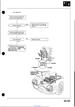
  • 1. From page 22-32 I Check for continuity between the each wires and body ground. Repair any short in wire(s) between the recirc. motor and control unit. Is there continuity? NO Test the recirculation control motor at the blower (page 22-89). NO Is the motor OK? Replace the motor. YES Substitute a known-good control unit and recheck. If symptomlindi- /;;t$;ac!gcooenstr~;gfirwlace the LT RECIRCULATIO CONTROL MOTOR 22-33 vnx.su
  • 2. Troubleshooting - Vent Door Control Motor Self-diagnosis indicator light I comes on: Indicates a problem in the vent door control motor circuit. Use a digital multimeter (KS-AHM32-03) to check it. The vent door control motor regulates the vent door according to output from the control unit. Problem in the vent door control I No.5 Turn the ignition switch OFF. Make sure all wires in the vent door control motor connector are securely attached. Make sure the linkage is free of obstructions. Remove the climate control unit (page 22-84). Leave the wire connected. I Turn the ignition switch ON. Set the temperature control dial at TEMP display 18, then measure battery voltage between No.5 terminal and body ground when turning temperature control dial at TEMP display 32. After, measure battery voltage between No. 19 terminal and body ground when turning temperature control dial at TEMP display 18. No:1 1 I I Substitute a known-good control unit and recheck. If symptom/indi<T* h ~~;a~~;,~.v;q;raplace t e To page 22-35 22-34 vnx.su Fjo.14
  • 3. (From page 22-34) J Turn the ignition switch OFF. Disconnect the 6-P connector from the vent door control motor. YEUBLK I GRNl RED Turn the ignition switch ON. Set the temperature control dial at TEMP display 18, then measure battery voltage between the YEL/BLK terminal and body ground when turning the temperature control dial at TEMP display 32. After, measure battery voltage between the YEL/BLU terminal and body ground when turning the temperature control dial at TEMP display 18. Is there battery voltage? YES BLKlGRN YELlWHT R e p a i r open in YEL/BLK or YELlBLU wires between the vent door control motor and control unit. Turn the ignition switch OFF. Disconnect the 14-P connector from the control unit. Check for continuity between YEL/BLK or YEL/BLU terminals and body grond. Is there continuitv? Reoair short in the YELlBLK or YELlBLU wires between the vent 1 tz control motor and control 1 Reconnect the 1,4Pconnector. ] To page 22-36 (cont’d) 22-35 vnx.su
  • 4. Troubleshooting - Vent Door Control Motor (cont’d) From page 22-35 From the back of the 14-P connector at the control unit, measure voltage between the No. 11 and body ground. Substitute a known-good control unit and recheck. If symptomlindiYES I Measure voltage between the GRN/RED terminal and body ground. I I Is there approx. 5V NO I Repair open in the GRNlRED wire between the vent door control motor and control unit. YES Turn the ignition switch OFF. Disconnect the 14-P connector p+q Check each wires for continuity: l YEUWHT wire l BLKIGRN wire <*e ffffKLE2xz: vent door control motor and con- To page 22-37 22-36 vnx.su
  • 5. From page 22-36 Check for continuity between the GRN/RED, YEL/WHT or BLK/GRN wire(s) and body ground. NO Repair short in the GRNIRED, YELANHT or BLKlGRN wire(s) between the vent door control motor and control unit. Test the vent door control motor at the heater (page 22-W. Replace the vent door control motor. YES Substitute a known-good control unit and recheck. If symptom/indication goes away, replace the original control unit. 22-37 vnx.su
  • 6. Troubleshooting - Power Circuits to A/C Control Unit First, check for blown No.33 (7.5A) and No.4 (15A) fuses. No heater and AIC in either manu- Remove the climate control unit (page 22-84). Disconnect the 30-P connector from the climate control unit. Turn the ignition switch ON. Measure voltage between the No.30 (WHT/YEL) terminal and body ground. Repair open in WHTlYEL (No.301 wire between the control unit and No.33 (7.5 A) fuse. YES Measure voltage between: l No.28 (YEL/BLK) terminal and body ground. l No.27 (YEL/BLK) terminal and body ground. , Is there battery voltage? I YES NO I Repair open in YELlBLK (No.27 or No.281 wire between the control unit and No.4 (15A) fuse. To page 22-39 22-38 vnx.su I
  • 7. From page 22-38 Check for continuity between: l No.25 (8LK) and body ground. l No.24 (BLK) and body ground. Is there continuity? NO Repair open BLK (No.24 or No.251 wire between the control unit and body ground. If wires are OK, check for poor ground at G401. Substitute a known-good control unit and recheck. If symptomlindi- 22-39 vnx.su
  • 8. Troubleshooting - Blower Motor SUB RELAY First, check for blown No.28(30A) and No.4(15A) fuse Blower motor does not run at all. I j r ~mho;m;;m;;vethe cover from sub kelay box A and re- I Turn the ignition switch ON. , Measure voltage between the BLU/WHT wire terminal (+ ) and body ground (- 1. NO, Is there battery voltage? YES Measure voltage between the YELlBLK wire terminal (+I and body ground (- 1. 1 Is there battery voltage? > I -T <’ Repair open in BLWVHT wire between the No.28 (30AI fuse and blower relay. YES To page 22-41 22-40 vnx.su
  • 9. From page 22-40 r 1 Test the blower relay: Connect battery power to relay terminal C, then connect terminal D to body ground. There should be continuity between terminals A and B with power connected, no continuity with power disconnected. Replace the blower relay. YES Check for continuity between the BLK wire terminal and body ground Repair open in BLK wire between the blower relay and body ground. If wire is OK, check for poor ground at 0301. YES Turn the ignition switch OFF. I Reinstall the blower relay. Disconnect the 2-P connector from the blower motor. BLOWER MOTOR CONNECTOR Turn the ignition switch ON. I To page 22-42 (cont’d) 22-41 vnx.su
  • 10. Troubleshooting Blower Motor (cont’d) BLOWER MOTOR CONNECTOR Measure voltage between the BLURED wire terminal (+I and body ground (- 1. Is there battery voltage? BLUIRED BLKIBLU From page 22-41 Repair open in BLUlRED wire between blower motor and blower relay YES Inspect the blower motor. Does the blower motor run? NOTE: Connect the battery power to the BLWRED wire terminal and connect the BLK/BLU wire terminal to body ground. The blower motor should runs. Replace the blower motor. I YES ; :;ntx?mi;;~h OFF. SUB RELAY Reconnect the connector to the 22-42 vnx.su f. _ e
  • 11. From page 22-42 rGizz+ NO Does the blower motor run? Repair open in BLKIBLU wire between blower motor and blower high relay. YES Turn the ignition switch OFF. 1 the BLK/BLU wire terminal and 1 Turn the ignitio; switch ON. Repair open in BLK wire between 1 ~!t~zLJL,,~;~~ Measure voltage between the YEL/BLK wire (+) terminal and body ground. Repair open in YELIBLK wire between ignition switch and blower high relay. YES To page 22-44 ‘j (cont’d) 22-43 vnx.su
  • 12. Troubleshooting . Blower Motor kont’d) From page 22-43 Test the blower high relay: Connect battery power to relay terminal C, then connect terminal D to body ground. There should be continuity between terminals A and 6 with power connected, no continuity with power disconnected. Replace the blower high relay. YES I i Turn the ignitio; switch OFF. # Reinstall the blower high relay. Remove the climate control unit (page 22-84). No.1 2 (ORNIWHT) e Disconnect the 30-P connector from the climate control unit. Connect a jumper wire between the ORN/WHT wire terminal and body ground. Turn the ignition switch ON. To page 22-45 a vnx.su
  • 13. From page 22-44 Repair open in ORNMfHT wire between blower high relay and climate control unit. Substitute a known-good control unit and recheck. If symptom/indication goes away, replace the original control unit. a a 22-45 vnx.su
  • 14. Troubleshooting - Blower Speed Controls Blower motor speed does not change. LT GRNlBLK Open the hood disconnect the 3-P power transistor connector from the blower harness connector. Connect a voltmeter between the YES Turn the FAN switch to the middle of its range. To v B To page 22-47 22-46 vnx.su
  • 15. From page 22-46 V B Connect a jumper wire between the BLK/BLU wire terminal and the BLK wire terminal. BLKIBLU 1 S e e troubleshooting, BLUlRED page YES I I Disconnect the 30-P connector from the control unit and the 2-P connector from the blower motor. I Check for continuity BLK/BLU wire. in the NO Is there continuity? 1YES Repar open in the BLK/BLU wire between the blower motor and control unit. Check for continuity between the BLK/BLU terminal and body ground. No.22 (BLKIBLU) Is there continuity? NO Repair short in the BLKlBLU wire between the blower motor and control unit. Replace the power transistor. (dont’d) 22-47 vnx.su
  • 16. Troubleshooting - Blower Speed Controls (cont’d) From page 22-46 Remove the climate control unit (page 22-841. ‘...I Disconnect the 30-P connector Check for continuity in the LT GRN/BLK wire. I I Is there continuity? NO Repair open in the LT GRNlBLK wire between the power transistor and control unit. YES Check for continuity between the No.8 (LT GRN/BLK) wire terminal and body ground. 1NO Substitute a known-good control unit and recheck. If symptomlindication goes away, replace the original control unit. vnx.su
  • 18. Troubleshooting A/C System First, check for blown fuses: NO. 4 (15 A), No. 36 (10 A), No. 37 (10 A), No. 21 (10 A). AK system does not work (cornpressor and condenser fans). Remove the climate control unit (page 22-84). Disconnect the 30-P connector from climate control unit. Turn the ignition switch ON. I 1 Measure voltage between the No. 13 (GRY/BLK) terminal (+ ) and body ground I-). NO To paw I Is there battery voltage? Repair open in one of the two BLK wires between the climate control unit and body ground. If the wires are OK, check for a poor ground at 6401. 22-51 YES Check for continuity between; l No.25 (BLK) terminal and body ground. l No.24 (BLK) terminal and body ground. YES / Substitute a known-good climate control unit and recheck. If symptomlindication goes away, replace original control unit. 22-50 vnx.su
  • 19. From page 22-50 1 1 Turn the ignition switch OFF. I Disconnect the 12-P connector from cooling fan control unit. I Substitute a known-good cooling replace the original control unit. 22-51 vnx.su
  • 20. -Condenser Fan First, check for blown fuses: NO. 4 (15 A), No.36 (10 A), No. 37 (10 A). One or both condenser fans does 1 z:~:~:::::;e / cover from sub ;elay / box A and re- Using a jumper wire, connect the VV-l~T/~RNwireterminaltobody l Do both condenser fans run? / L-- To page 22-55 YES Connect a jumper wire between the WHT/GRN wire terminal and ELK wire terminal. Do both condenser fans run? YES Turn the ignition switch ON. To page 22-53 22-52 vnx.su
  • 21. From page 22-52 Measure the voltage between the YEL/BLK wire terminal (+) and body ground (- 1. NO I YES Repair open in the YELlBLK wire between the No. 4 fuse (15 A) and condenser fan relay. Test the condenser fan relay: Connect battery power to relay terminal C, then connect terminal D to body ground. There should be continuity between terminals A and B with power connected, no continuity with power disconnected. Replace the condenser fan relay. Turn the ignition switch OFF, and reinstall the condenser fan relay. Disconnect the 12-P connector from the cooling fan control unit. Turn the ignition switch ON. To page 22-54 (cont’d) 22-53 vnx.su
  • 22. Troubleshooting - Condenser (cont’d) From page 22-53 Measure voltage between the ORN/BLU terminal (+) and body ground t-1. NO Is there battery voltage? , I Repair open in the ORNlBLU wire between the condenser fan relay and cooling fan control unit. fan control unit and recheck. If symptom/indication goes away. replace the original control unit. 22-54 vnx.su
  • 23. V From page 22-52 Right side: WHT Left side: WHTIBL A Disconnect the 2-P connector from inoperative condenser fan(s). I I Measure voltage: Right fan: WHT wire terminal and body ground. Left fan: WHT/BLU wire terminal and body ground. I”. Is there battery voltage at terYES Repair open in WHT wire between the No. 37 fuse (10 A) and the right fan, or in the WHTIBLU wire between the No. 36 fuse (IOA) and the left fan. Test both condenser fan motors. Connect battery power to the WHT and WHT/BLU wire terminals and connect the WHT/GRN terminal to body ground. Both fans should run. NO Does the fan motor(s) OK? I YES r between the condenser fan motor Replace the faulty fan motor. 1 22-55 vnx.su
  • 24. Troubleshooting - A/C Compressor :irst, check for blown fuses: No. 21 (IO A), No. 4 (15 A). Compressor clutch does not engage. When AIC is turned on with engine running. Remove the compressor clutch relay from sub relay box A. c / Is there battery voltage? ..NW YES , Repair open in the PNKlORN wire between the No. 21 (IO A) fuse and compressor clutch relay. I Turn the ignition switch ON. Measure voltage between the YEL/BLK wire terminal (+I and body ground (- ). NO ’ Is there battery voltage? Repair open in the YELlBLK wire between the No. 4 (16 A) fuse and compressor clutch relay. YES To page 22-57 22-56 vnx.su
  • 25. From page 22-56 Test the compressor clutch relay: Connect battery power to relay terminal C, then connect terminal D to body ground. There should be continuity between terminals A and Et with power connected, no power with power disconnected. NO Is the relay OK? YES I 1 Turn the ignition switch OFF. Remstall I Replace the compressor clutch relav. I I 1 the compressor clutch p Remove the panel from behind the passenger seat. Disconnect the 4 connectors from PGM-FI-ECU. Connect teh ECU test harness connectors to the ECU. Turn the ignition switch ON. I--+ ECU TEST HARNESS Measure battery voltage between NO Is there battery voltage? Repair open in the REDlBLU wire between the compressor clutch relay and PGM-FI-ECU. YES To page 22-58 (cont’d) 22-57 vnx.su
  • 26. Troubleshooting - A/C Compressor (cont’d) From page 22-57 ECU Start the engine and connect a jumper wire between test harness terminal Al 5 and body ground. ECU TEST HARNESS Al5 I Does compressor clutch engage? I Turn the ignition switch OFF. YES B L7 Using a jumper wire, connect C3 test harness terminal to body ground. To page 22-61 NO Does compressor clutch engage? Substitute a known-good PGM-FIECU and recheck. If symptomiindication goes away, replace the original ECU. YES Turn the ignition switch OFF. ? c3 I A To page 22-59 22-58 vnx.su I
  • 27. From page 22-58 Disconnect the test harness, and reconnect the connectors to the BRNlBLK Disconnect the 4-P connector from the pressure switch. BLK YES Check refrigerant pressure. If pressure good, replace AIC pressure switch. NO Repair open in the BLK wire between the pressure switch and body ground or poor ground (0302). Does compressor clutch engage? NO Turn the ignition switch OFF. I Check for continuity between the 8LK wire terminal and body ground. Is there continuity? YES To page 22-60 (cont’d) 22-59 vnx.su
  • 28. Troubleshooting I A/C Compressor (cont’d) From page 22-59 connector from the cooling fan Check for continuity of BRN/BLK wire between the cooling fan con/ t r o l u n i t a n d prey” s w i t c h . Repair open in the BRNIBLK wire between the cooling fan control unit and pressure switch. YES 11 Start the enginei NO Does compressor clutch engage YES Repair open in the BLWBLK wire between PGM-F&ECU and cooling fan control unit. Substitute a known-good cooling symptom/indication goes away. replace the original control unit. 22-60 vnx.su
  • 29. From page 22-58 B ? Disconnect the connector from compressor. Turn the ignition switch ON. g 1 r o u n d t-1. RED Repair open in the RED wire between the compressor clutch relay and compressor. Is there battery voltage? YES ( Replace the compressor clutch. 1 22-6 1 vnx.su
  • 31. -Replacement 1. 2. Remove the spare tire (refer to Owner’s manual). Remove the spare tire holder. 4. * CORROSION RESISTANT BOLT Remove the sub relay box A and the water drair duct. Disconnect the connectors from the blower motor, power transistor and recirculation contra motor. Q CORROSION RESISTANT BOLT 4 6 mm bolt I?r 6 mm bolt DUCT BLOWER, POWER TRANSISTOR, and RECIRC. MOTOR CONNECTORS * 6 mm bolt- 5. 0 Remove the blower mounting bolts, then remove the blower. ~2 CORROSION RESISTANT BOLT 3. Disconnect the battery cables, loosen the hold-down bracket nuts, and remove the hold-down bracket. Then, remove the battery. BATTERY ab 6. Install the blower in the reverse order of removal, then make sure it runs and doesn’t leak any air. BRACKET 22-63 vnx.su
  • 32. Recirculation Control Motor - Replacement 1. 2. 4. Remove the blower (previous page). Remove the recirculation control motor cover from the blower (3 screws). REClkCULATlON CONTROL MOTOR COVER 3. Remove the recirculation control motor (I connector and 3 screws). RECIRCULATION CONTROL MOTOR L 22-64 vnx.su Install the recirculation control motor in the reverse order of removal. Apply battery voltage (page 22-89) and watch the door movement. Make sure that the recirculation door moves smoothly without binding. Make sure the motor doesn’t pull the door too far.
  • 33. A/C Service Tips and Precautions 1. 2. 3. 4. 5. 6. Always disconnect the negative cable from the battery whenever replacing air conditioner parts. Keep moisture and dust out of the system. When disconnecting any lines, plug or cap the fittings immediately; don’t remove the caps or plugs until just before you reconnect each line. Before connecting any hose or line, apply a few drops of refrigerant oil to the O-ring. When tightening or loosening a fitting, use a second wrench to support the matching fitting. When discharging the system, use a refrigerant recovery system; don’t release refrigerant into the atmosphare. And refrigerant oil after replacing the following parts: Condenser . . . . . . . . . . . . . . . . . . . . . . . . 10 cc (l/3 fl oz) Evaporator . . . . . . . . . . . . . . . . . . . . . . . . 10,cc (l/3 fl OL) Line or hose . . . . . . . . . . . . . . . . . . . . . 20 cc fl oz) (2/3 Receiver . . . . . . . . . . . . . . . . . . . . . . . . . . . 10 cc (l/3 fl 02) Compressor.. . . . . . . . . . . . . . . . . . . . . On compressor replacement, subtract the volume of oil drained from the removed compressor from 80 cc (2 2/3 fl 02). and drain the calculated volume of oil from the new compressor: 80 cc (2 2/3 fl OZ)-Volume of oil from removed compressor=Volume to drain from new compressor. Don’t overtighten fittings; you could damage them. Leaks are caused by faulty O-rings, overtightening won’t stop them. ft CORROSION RESISTANT BOLT @ Suction hose and discharge hose to AK lines . . . . . . . . . . . . . . .._..... 22 N’m (2.2 kg-m, 16 lb-ft) @ Discharge line C (both side) . . . .._................. 23 N*m (2.3 kg-m, 17 lb-ft) @ Condenser line A (both side) . . . . . . . . . . . . . . . . . . . . . . . 23 N*m (2.3 kg-m, 17 lb-ft) @ Condenser line C to left side 14 N-m (1.4 kg-m, 10 lb-ft) condenser . . . . . . . . . . . . . . . . . . . . . . . . @ Receiver-dryer . . . . . . . . . . . . . . . . . . 14 N-m (1.4 kg-m, 10 lb-ft) @ @ @ @ @ @ Receiver line and suction line to heater assembly . . . . . . . . . . . . . . . . . . . . . . . . . 22 N-m (2.2 kg-m, 16 lb-ft) Compressor hose mounting bolts . . . . . . . . . . . . . . . . . . . . . . . . . . . . . . . 22 N-m (2.2 kg-m, 16 lb-ft) Compressor mounting bolts . . . ..a......................... 25 N-m (2.5 kg-m, 18 lb-ft) Compressor bracket mounting bolts . . . . . . . . . . . . . . . . . 50 N-m (4.5 kg-m, 36 lb-ft) Idler pulley center nut . . . . 45 N.m (4.5 kg-m, 32.5 lb-ft) * 6 mm bolt . . . . . . . . . . . . . . . . . . 10 N’m (1.0 kg-m, 7.2 lb-ft) When handling refrigerant (R-12): 0 Always wear eye protection. l Do not let refrigerant get on your skin or in your eyes. If it does: - Do not rub your eyes or skin. - Splash large quantities of cool water in your eyes or on your skin. - Rush to a physician or hospital for immediate treatment. Do not attempt to treat it yourself. l Keep refrigerant containers (cans of R-12) stored below 40°C (100°F). l Do not handle or discharge refrigerant in an enclosed area near an open flame; it may ignite and produce a poisonous gas. l The ozone is fragile layer surrounding the earth which acts as a shield against the sun’s ultraviolet radiation. Chlorine from chemicals called chlorofluorocarbons (CFCs) destroy the ozone in the stratosphere. Automotive air conditioning systems currently use chlorofluorocarbons as the refrigerant. Auto air conditioning service equipment has been developed to minimize the release of CFCs to the atmosphere. All service procedures should be performed using this equipment and the manufactuer’s instructions. 22-65 vnx.su
  • 34. Heater-Evaporator Unit - Replacement SRS wire harness is routed near the heater. cM!m AllDoSRS wire harnesses and connectors colored yellow. not use electrical test equipment 5. are on Remove all refrigerant from the A/C system with a refrigerant recovery system. (page 22-93). 6. Disconnect the receiver line and the suction line from the evaporator. Cap the open fittings immediately to keep moisture out of the system. these circuits. CAUTION: Be careful not to damage the SRS wire harnesses when servicing the heater. 1. RECEIVER PIPE Remove the blower (page 22-63). 2. When the engine is cool, drain the coolant from the radiator (Section IO). m 0 Do not remove the radiator cap when the engine is hot; the coolant is under pressure and could severely scald you. Keep hands away from the radiator fan. The fan 0 may start automatically without warning and run for up to 30 minutes, even after the engine is turned off. CAUTION: Radiator coolant will damage paint. Quickly rinse any spilled coolant off painted surfaces. 3. Disconnect the heater hoses at the heater. Coolant will run out when the hoses are disconnected, drain it into a clean drip pan. 4. SUCTION PIPE 7. Remove the dashboard (Section 20). 8. Remove the heater duct. Disconnect the heater valve cable from the heater valve. 9. Remove the mounting bolts{41 and disconnect the connectors from control units and evaporator temperature sensor connector from the control unit bracket, then remove the control unit bracket. --75; EVAPORATOR TEMPERATURE HEAiER VALVE CABLE 10. Remove the enclosure woofer. vnx.su .
  • 35. 11. Disconnect the connectors from all the actuators and sensors attached to the heater-evaporator. 15. If necessary, adjust the heater valve cable: l Set the air mix control motor at COLD position (page 22-90). 12. Remove the mounting bolts(2-under the dash) and nuts(2-under the hood), then remove the heaterevaporator through the passenger door. l Connect the end of the cable to the heater valve arm. a: CORROSION RESISTANT BOLT HEATER-EVAPORATOR l Gently slide the cable outer housing back from the end enough to take up any slack in the cable, but not enough to make the other end move the arm on the air mix motor. Then snap the clamp down over the cable housing. CLAMP NUTS HEATER VALVE 6x20 10 N-m (1.0 kg-m, 7.2 lb-ft) 13. Install in the reverse order of removal, and: l Apply sealant to the A/C line grommets. l Do not interchange the inlet and outlet heater hoses. Make sure that the hose clamps are tight. 14 Fill the radiator and reservoir tank with the proper coolant mixture. Bleed the air from the cooling system (Section IO). CAUTION: Follow the sequence described in the air bleed procedure. If you don’t, you may leave air in the system which could damage the engine. II HEATER CABLE VALVE 16. Turn the blower on and make sure that there is no air leakage. 17. Charge the system (page 22-93-95) and test Performance (page 22-96). 22-67 vnx.su
  • 36. Evaporator Temperature Sensor. Coolant Temperature Sensor - Removal - Removal Disconnect the connector, and remove the coolant temperature sensor clip and the sensor. COOLANT TEMPERATURE SENSOR Give the evaporator temperature sensor a quarter turn and then pull out it. EVAPORATOR / TEMPERATURE SENSOR 22-68 vnx.su
  • 37. Vent Door Control Motor Mode Control Motor - Replacement - Replacement 1. Remove the mounting screws, then remove the vent door control motor. 1. WI Remove the mounting screws, then remove thl mode control motor. VENT DOOR CONTROL MOTOR 2 Install the vent door control motor in the reverse order of removal. Then apply battery voltage (page 22-90) and watch the door move. l l Make sure that the vent door moves smoothly without binding. Make sure the motor doesn’t pull the vent door too far. MODE CONTROL MOTOR 2. install the mode control motor in the reverse order of removal. Then apply battery voltage (page 22-91) and watch the doors move. l l Make sure that the HEAT and DEF doors moves smoothly without binding. Make sure the motor doesn’t pull the HEAT and DEF doors too far. 22-69 vnx.su
  • 38. Air Mix Control Motor - Replacement 1. Disconnect the heater valve cable from the air mix control motor. 4. HEATER VALVE If necessary, to adjust the heater valve cable; 0 Set the air mix control motor at COLD position (page 22-90). 0 Hold the end of the cable housing against the stop on the cable. Then snap the clamp down over the housing. 0 After adjusting the cable, make sure that the air mix control motor still moves smoothly without binding. STOP CLA AIR MIX CONTROL MOTOR 2. Remove the air mix control motor (3 screws, 1 connector). HEATER VALVE CABLE AIR MIX CONTROL MOTOR 3. AIR MIX CONTROL Install the air mix control motor in the reverse order of removal. Then apply battery voltage (page 22-90) and watch the door move. Make sure that the air mix door moves smoothly without binding. Make sure the motor doesn’t pull the air mix door too far. 22-70 vnx.su
  • 39. Heater-Evaporator Unit -Disassembly/Reassembly 1. Remove the heater core cover, remove the pipe clamp, then pull out the heater core. 2. Remove the lower half of the housing, then remove the evaporater. 3. Remove the expansion valve if necessary. HEATER CORE PIPE CLAMP EXPANSION VALVE AIR MIX DOOR 1 TAPE Replace CAPILLARY TUBE must be touching the suction line. LOWER HALF OF THE HOUSING 4. Assemble the heater-evaporator unit in the reverse order of disassembly. Hold the expansion valve capillary tube down against the suction line, and wrap it with tape to hold it there. 22-7 1 vnx.su
  • 40. Heater-Evaporator Unit “HEAT” Door Adjustment - “DEF” Door Adjustment :onnect the control rod to he clip. 0 Turn this lever all the way clockwise and hold it there. 0 / Reposition gear 2 so this mark lines up with the mark on gear 1. Loosen this screw in gear 2. 0 GEAR 1 GEAR 2 Turn this Ieve; clockwise and hold it against its stop. a 22-72 vnx.su
  • 41. Condenser - Description Dual condensers are mounted behind the right and left side of the front bumper as shown. The cooling efficiency of paralleldual condensers is as good as or better than a single condenser mounted in front of radiator. RECEIVER/ DRYER RIGHT CONDENSER 22-73 vnx.su
  • 42. . Condenser Assembly Replacement Disconnect the battery negative terminal. Use a refrigerant recovery system to discharge the refrigerant (page 22-93). 3. Disconnect the discharge line and the condenser lines from the condenser. Cap the open fittings immediately to keep moisture and dirt out of system. 1. 2. (Right 4. Disconnect the connector from the condenser fan motor, remove the mounting belts(2) and nut, then remove the condenser. *: CORROSION RESISTANT BOLT (Right Condenser) Condenser) NUT V RIGHT CONDENSER * MOUNTING BOLTS 10 N-m (1.0 kg-m, 7.21 lb-ft) DISCHARGE LINE C (Left Condenser) NUT / (Left Condenser) CONDENSER Q MOhNTlNG BOLTS 10 N’m (1.0 kg-m, 7.2 lb-ftl 5. CONDENSER LINE A 22-74 vnx.su Install the condenser in the reverse order of removal; l Replace O-rings with new ones each fitting. l Charge the system (page 22-93-95) and test its performance (page 22-96).
  • 43. 1. 2. Disassembly/Reassembly Remove the bolts and nuts (4). Then separate the condenser duct from the shroud, and remove the condenser. Remove the fan mounting screws (31, then remove the fan from the shroud. CONDENSER I CONDENSER DUCT NUT 10 N-m (1.0 kg-m, 7.2 lb-it) SCREW SHROUD SPACER CONDENSE6 FAN 3. Assemble the condenser in the reverse order. Be careful not to damage the tabs on the condenser shroud when you attach it to the air intake duct. 22-75 vnx.su
  • 44. Compressor Description This compressor is a Nippondenso piston type. A revolving inclined disc drives the surrounding 10 reciprocating pistons. thus compressing the refrigerant. As the inclined disc revolved, it pushes the pistons, protected by a ceramic shoe, CENTER BOLT 4 PRESSURE PLATE _e 4e SHIMS SNAP RING B PULLEY SNAP RING A FIELD COIL 22-76 vnx.su
  • 45. -Replacement 1 1. If the compressor still works, run the engine at idle for a few minutes with the A/C on, then shut the engine off and disconnect the negative cable from the battery. 2. Use a refrigerant recovery system to discharge the refrigerant from the system (page 22-93). 3. Disconnect the compressor connector. 7. Loosen the idler pulley center nut and adjusting bolt, then remove the belt from compressor. ADJUSTING BOLT 12 N-m 11.2 kg-m. COMPRESSOR CONNECTOR IDLER PULLEY CENTER NUT 45 N-m (4.5 kg-m, 32.5 lb-ft) 4. 5. 6. Raise the car on a hoist. Make sure it’s properly supported (Section I). Remove the front beam (Section 5). Disconnect the suction and discharge hoses from the compressor. Cap the open fittings immediately to keep moisture and dirt out of the system. 8. Remove the four compressor mounting bolts and compressor. DISCHARGE HOSE SUCTION f&3 COMPRESSOR MOUNTING BOLTS 25 N-m (2.5 kg-m, 18 lb-ft) (cont’d) 22-77 vnx.su
  • 46. Compressor - Replacement (cont’d) 9. If necessary, remove the compressor bracket (4 bolts, plus 1 from the idler pully bracket). 0 Check the idler pulley bearing for play and drag. Replace it with a new one if it’s noisy or has excessive play or drag. o- 10x65 50 N*m 15.0 kg-m, 36 lb-ft) IDLER PULLEY BRACKET BOLT / I 0 12 N.m (1.2 kg-m, 8.7 lb-ftt 10x50 50 N-m (5.0 kg-m, 36 lb-ft) 4 5 N*m (4.5 kg-m, 36 lb-ft) COMPRESSOR BRACKET IO. If necessary remove the idler pulley (2 more bolts). 11. Install in the reverse order of removal. If you’re installing a new compressor, drain all the refrigerant oil out of the old compressor and measure its volume. Subtract the volume of old oil from 80 CC (2 l/3 floz); the result is the amount of oil you should drain from the new compressor (through the suction fitting). 12. Adjust the compressor belt (page 22-79). After adjusting the belt, tighten the pully center nut. Then tighten the adjusting bolt securely. 13. Charge the system (page 22-93-96). 14. Test system performance (page 22-961. IDLEk PULLY ASSEMBLY 22-78 vnx.su
  • 47. - Compressor Belt Adjustment “New belt” refers to a belt which has been used less than 5 minutes on a running engine. 0 “Used belt“ refers to a belt which has been used or+&+ ;..l- s‘.: ;, a running engine for 5 minutes or more. L*:;,+, “d ,. NOTE: Check for belt damage. If necessary, replace-’ the belt. l ADJUSTING BOLT 12 N-m (1.2 kg-m, 8.7 lb-ft) PULLEY CENTER NUT 45 N-m 14.5 kg-m, 32.5 lb-ft) 22-79 vnx.su
  • 48. Compressor Clutch 1. Inspection Check pulley bearing play and drag by rotating the pulley by hand. Replace the pulley with a new one if it is noisy or has excessive play/drag. 3. Measure the clearance between the pulley and pressure plate all the way around. If the clearance is not within specified limits, the pressure plate must be removed and shims added or removed as required, following the procedure on the next page. CLEARANCE: 0.5 -+ 0.15 (0.020 _+ 0.006 in) NOTE: The shims are available in three sizes: 0.1 mm, 0.2 mm and 0.5 mm of thickness. PULLEY / 2. Check resistance of the field coil: Field Coil Resistance: 3.6f0.2 ohm at 2o”c (68OF) If resistance is not within specifications, replace the 22-80 vnx.su
  • 49. Clutch Overhaul 0 3. 1. Remove the center bolt. Use circlip pliers to remove snap ring B, then remove the pulley. CENTER BOLT 12 N-m (1.2 kg-m, 9 lb-ft) SNAP RING B PULLEY P/N 10204 2. Remove the pressure plate and shim(s) not to lose the shims. taking care PRESSURE PLATE SHIMS (cont’d) 22-81 vnx.su
  • 50. Compressor Relief Valve Replacement Overhaul (cont’d) 4. 1. Remove snap ring A and the field coil. Remove the relief valve and O-ring. Don’t let any compressor oil run out. SNAP RING A FIELD COIL O-RING RELIEF VALVE 13.5 N*m (I .35 kg-m, 9.8 lb-ft) RE;EF VALVE CAP 2. Install parts in the reverse order of removal, and: 3. Apply compressor oil to the O-ring. 0 Install the field coil with the wire side facing UP (see above). 4. Install and tighten the relief valve. 5. 5. Clean off the mating surface. Charge the system and check for leaks, then push the cap into the valve. 0 Clean the pulley and compressor sliding surfaces with non-petroleum solvent. l Check the pulley bearings for excessive play. 0 Make sure the circlip fits in its groove properly. l Apply locking agent to the threads on the center bolt. l Make sure that the pulley turns smoothly, after it’s reassembled. 22-82 vnx.su I) -
  • 52. Component Removal/Replacement - Climate Control Unit SRS wire harness is routed near the console. 4. rmmi Remove the ashtray (lift up on the door to pop it out), then remove the 2 screws behind it. All SRS wire harnesses and connectors are colored yellow. Do not use electrical test equipment on these circuits. ASHTRAY CAUTION: Be careful not to damage the SRS wire harnesses when servicing the console. 1. Carefully pry the clock out of the dash and disconnect it. CAUTION: Be careful not to damage the center console panel and the dashboard. 2. Remove the center dash vent (2 screws). 3. Remove the 2 screws from the top of the console panel. CLOCK 5. Remove the console storage box (lift out the bottom panel and remove 4 screws). 6. Remove the screw from the end of the console panel. IFNT 22-84 vnx.su
  • 53. - In-car Temperature Sensor 7. Pull the parking brake handle all the way up, iift the panel and disconnect the 2 connectors from it, then carefully lift the panel off past the shift lever. Remove the center console panel. The in-car temperature sensor assembly includes a small fan (aspirator fan) to draw air past the sensor. SRS wire harness is routed near the console. m All SRS wire harnesses and connectors are colored yellow. Do not use electrical test equipment on these circuit. CENTER CONSOLE PANEL CAUTION: Be careful not to damage the SRS wire harnesses when servicing the console. I 1. 2. 8. Remove the center console panel as described in step 1 - 7 in the first column (Climate Control Unit). Remove the mounting screws 12) and remove the in-car temperature sensor from the under side of the console panel. Be careful not to damage the console panel. Remove the screws (41, then pull out the control unit, disconnect its connectors and remove it from the dashboard. IN-CAR TEMPERATURE SENSOR UNDER SIDE bF CENTER CONSOLE PANEL / CLIMATE CONTROL. UNIT SRS CONTROL UNIT 22-85 vnx.su
  • 54. Component Removal/Replacement -Ambient Temperature Sensor Remove the screw, disconnect the wire harness and then remove the ambient temperature sensor. Be careful not to damage the front grille and front bumper. - Sunlight Sensor With a small screwdriver, carefully pry the sunlight sensor out of the dashboard and disconnect its wire harness. Protect the dashboard; cover it with a shop towel before you pry against it. SUNLIGHT SENSOR AMilENT TEMPERATURE SENSOR 22-86 vnx.su
  • 55. Component Tests In-car Temperature Sensor Ambient Temperature Sensor - Compare the resistance reading between No. 1 and No. 2 terminals of the in-car temperature sensor with specifications shown in the following graph: It should be within specification. Compare the resistance reading between terminals of the ambient temperature sensor with specificatoins shown in the following graph: It should be within specification. o“F oc a - 32 (0) 50 (IO) 66 (20) .86 104 122 OF (30) (40) OC (-10) (50) 35 32 5 0 6 8 86 104 122 (0) (IO) 120) 130) (40) i501 TEMPERATUER TEMPERATUER CAUTION: The sensor uses a thermistor which can be damaged if high current is applied to it during testing. Therefore, use a circuit tester that puts out a measuring current of 1 mA or less. CAUTION: The sensor uses a thermistor which can be damaged if high current is applied to it during testing. Therefore, use a circuit tester that puts out a measuring current of 1 mA or less. 22-87 vnx.su
  • 56. Component Tests Coolant Temperature sensor Evaporator Temperature Sensor - Compare the resistance reading between terminals of the coolant temperature sensor with specifications shown in the following graph: It should be within specification. Compare the resistance reading between terminals of the evaporator temperature sensor with specification shown in the following graph: It should be within specification. 20 16 10 6 0 6 F 32 Oc (0) C ~0)(10)(20)~80)~40~~601~60~~70~~80~ 50 (IO) 68 (201 86 (301 TEMPERATURE TEMPERATURE CAUTION: The sensor uses a thermistor which can be damaged if high current is applied to it during testing. Therefore, use a circuit tester that puts out a measuring current of 1 mA or less. CAUTION: The sensor uses a thermistor which can be damaged if high current is applied to it during testing. Therefore, use a circuit tester that puts out a measuring current of 1 mA or less. 22-88 vnx.su
  • 57. - Recirculation Control Motor - Sunlight Sensor Measure the voltage between the terminals with the sensor out of direct sunlight. l With the connector connected (probe the back of it): 1.420.2 V l With the connector disconnected: 0.1 - 0.2 V 1. Connect battery power to No. 1 terminal of the recirculation control motor, and connect to the No. 2 terminal to ground. The motor should run. If it doesn’t, reverse the connections; the motor should then run. 2. Check for continuity between the terminals of the recirculation control motor according to this table. 22-89 vnx.su
  • 58. Component Tests t Air Mix Control Motor - Vent Door Control Motor 0 Connect battery power to the No. 1 terminal of the air mix control motor, and connect to the No. 2 terminal to ground; the air mix control motor should run, and stop at HOT. If it doesn’t, reverse the connections: then the motor should run, and stop at COLD. 0 Apply 5 V between the No. 3 terminal and the No. 5 terminal, then measure the voltage between the No. 3 terminal and the No. 4 terminal. The reading should be; 4.7 kO.7 V at HOT position. 0.3 kO.7 V at COLD pcosition. 1. 2. Connect battery power to the No. 1 terminal of the vent door control motor, and connect to the No. 2 terminal to ground; the vent door control motor should run, and stop at CLOSE. If it doesn’t, reverse the connections; then the motor should run, and stop at OPEN. Apply 5 V between the No. 3 terminal and the No. 5 terminal, then measure the voltage between the No. 4 and the No. 5 terminals. The reading should be; 4.7 kO.7 V at OPEN position. 0.3 kO.7 V at CLOSE positon. - I vnx.su I
  • 59. - Mode Control Motor 1. - Aspirator Fan Connect battery power to the No. 1 terminal of the mode control motor, and connect to the No. 2 terminal to ground. The motor should run, and stop at VENT. If it doesn’t reverse the connectinos; the motor should run, and stop at DEF. Connect battery power to the BRN/YEL terminal of the connector, and connect the BLK terminal to ground. The fan should run. BLK 2. Plug the connector back in to the motor. Then operate the MODE switch on the control panel, and in each mode probe the back of the connector to check for continuity between terminals according to the table. 22-9 1 vnx.su
  • 60. Control Unit Adjustment Component Tests IRelay There should be continuity between the A and B terminals when the battery is connected to the C and D terminals. There should be no continuity when the battery is disconnected. The calibration switch can raise or lower the set temperature by f3OF (1.5OC) in relation to the digitallydisplayed temperature. Calibration switch 5~ 3OF (+ 1.53=’ A C E v v B D 22-92 vnx.su
  • 61. A/C System Service - Evacuation - Discharge 1. 0 Keep away from open flames. The refrigerant, although nonflammable, will produce a poisonous gas if burned. _ l Work in a well-ventilated area. Refrigerant evaporates quickly, and can force all the air out of a small enclosed area. 1. Connect a Refrigerant Recovery System to the A/C system. 2. Operate the Refrigerant Recovery System according to the manufacturer’s instractions. IMPORTANT: Do not vent refrigerant to the atmosphere. The chlorofluorocarbons (CFCs) used in conventional refrigerant (R-12) may damage the earth’s ozone layer. Always use UL-listed, refrigerant recovery/recycling equipment to extract the refrigerant before you open an A/C system to make repairs. Follow the equipment manufacturer’s instructions. Refrigerant Recovery/Recycling System. vnx.su When an A/C System has been opened to the atmosphere, such as during installation or repair, it must be evacuated using a vacuum pump. (If the system has been open for several days, the receiver/dryer should be replaced). 2. Attach an Air Conditioning Service Station as shown. Follow the equipment manufacturer’s instructions. NOTE: If low pressure does not reach more than 700 mm hg (27 in-Hg) in 15 minutes, there is probably a leak in the system. Partially charge the system and check for leaks (see Leak Test).
  • 62. A/C System Service - Leak Test mlm When handling refrigerant (R-l 2): Always wear eye protection. 0 Do not let refrigerant get on your skin or in your eyes. If it does: - Do not rub your eyes or skin. - Splash large quantities of cool water in your eyes or on your skin. - Rush to a physician or hospital for immediate treatment. Do not attempt to treat it yourself. l Keep away from open flame. Refrigerant, although non-flammable, will produce poisonous gas if burned. l Work in well-ventilated area. Refrigerant evaporates quickly, and can force all the air out of a small, enclosed area. l IMPORTANT: Do not vent refrigerant to the atmosphere. The chlorofluorocarbons (CFCs) used in conventional refrigerant (R-12) may damage the earth’s ozone layer. Always use UL listed, refrigerant recovery/recycling equipment to extract the refrigerant before you open an A/C system to make repairs. Follow the equipment manufacturer’s instructions. 1. Attach an Air Conditioning Service Station as shown. 2. Open high pressure valve to charge the system to about 100 kPa (14 psi), then close the supply valve. 3. Check the system for leaks using a leak detector. 4. If you find leaks that require the system to be opened (to repair or replace hoses, fittings, etc.), discharge the system according to the Discharge Procedure on page 22-93. 5. After checking and repairing leaks, the system must be evacuated (see System Evacuation on page 22-93). vnx.su I HIGH-SIDE ADAPTER Kent-Moors: P/N J26499 Snap-on: P/N ACT 135
  • 63. Charging Procedures Refrigerant capacity: 900-950 g (32-34 02) m Always wear eye protection when charging the system. CAUTION: Do not overcharge the system; the compressor will be damaged. Attach an Air Conditioning Service Station as shown. Follow the equipment manufacturer’s instructions. HIGH-SIDE ADAPTER Kent-Moors: P/N J25499 P/N ACT135 22-95 vnx.su
  • 64. Performance Test The performance test will help determine if the air conditioning system is operating within specifications. 1. Connect the hoses as shown. 2. Insert a thermometer in the vent outlet. Determine the relative humidity and air temperature by calling the local weather information line. 3. Test conditions: l Avoid direct sunlight. 1 0 Open engine cover. 0 Open front doors. l Set the temperature control dial to max cold and push the VENT and fresh air buttons. 0 Turn the fan switch to MAX. 0 Run the engine at 1,500 RPM. l No driver or passengers in vehicle. ‘4. After running the air conditioning for 10 minutes under the above conditions, read the delivery temperature from the thermometer in the dash vent and the high and low system pressure from the AK gauges. 5. To complete the charts: 0 Mark the delivery temperature along the vertical line. 0 Mark the intake temperature fair temperature) along the bottom line. 0 Draw a line straight up from the air temperature to the humidity. 0 Mark a point one line above and one line below the humidity level. (I 0% above and 10% below the humidity level) 0 From each point, draw a horizontal line across to the delivery temperature. l The delivery temperature should fall between the two lines. 0 Complete the low side pressure test and high side pressure test in the same way. 22-96 vnx.su HIGH-SIDE ADAPTER Kent-Moors: P/N J25499 Snap-on: PIN ACT 135
  • 65. (Without fog lamp) (With fog lamp) HUMIDITY 80% kPa z =) kPa HUMIDITY 80% 25001 w 2500 5 1 8 u 2000 E * K.CM t (PSI) (501- kPa 3 lilw 4 0 0 a n1000 (Psi) ,,“.C 1 kPa (50) 400 (40) 3 0 0 I Mol. 300 (3Ol- 200 (2017 (lo)- 0 EMPERATURE 32 68 77 86 85 104 120) (251 130) (351 MO) (0) (20) (26) (30) (35) MO) INTAKE TEMPERATURE INTAKE TEMPERATURE 22-97 vnx.su I f ; 100 2 TEMPERATURE (0) I i
  • 66. Pressure Test NOTE: Performance Test on page 22-96. TFCT RF91 II l-C 1 RFI ATFD IL”, 11~~-~11 * .__. . . SYMPTOMS -...- PROBABLE CAUSE -- -. . REMEDY After stopping compressor, pressure drops to about 196 kPa (28 psi) quickly, and then falls gradually Air in system No bubbles in sight glass when condenser is cooled by water Discharge (high) pressure abnormally high Evacuate system: then recharge Evacuation: page 22-93 Recharging: page 22-95 Excessive refrigerant in system Discharge refrigerant as necessary Reduced or no air flow through condenser. l l Clogged condenser or radiater fins Condenser or radiator fan not working properly Line to condenser is excessively hot Discharge pressure abnormally low Restricted flow of refrigerant in system Excessive bubbles in sight glass; condenser is not hot High and low pressures are balanced soon after stopping compressor insufficient refrigerant in system l Clean l Check voltage and fan rpm Expansion valve l l Check for leak Charge system l Outlet of expansion valve is not frosted, low pressure gauge indicates vacuum Faulty expansion valve Excessive bubbles in sight glass; condenser is not hot Insufficient refrigerant Expansion valve is not frosted and low pressure line is not cold. Low pressure gauge indicates vacuum l Frozen evaporator Run the fan with compressor off then check capillary tube. Expansion valve frosted Clogged expansion valve Clean or Replace Receiver dryer is cool (should be warm during operation) Suction pressure abnormally high l Discharge temperature is low and the air flow from vents is restricted Suction flow) pressure abnormally low Faulty compressor discharge or inlet valve Faulty compressor seal Clogged receiver dryer Replace l l Low pressure hose and check joint are cooler than around evaporator l l Suction pressure is lowered when condenser is cooled by water Expansion valve open too long Loose expansion valve Excessive refrigerant in system High and low pressure are equalized as soon as the compressor is stopped Suction and discharge pressures abnormally high Frozen expansion valve Faulty expansion valve l Reduced air flow through condenser l l l l Replace compressor Replace Check for leaks. Charge as required. Replace expansion valve Repair or Replace. Discharge refrigerant as necessary Faulty gasket Faulty high pressure valve Foreign particle stuck in high pressure vlave Replace compressor Clogged condenser or radiator fins Condenser or radiator fan not working properly l l Clean condenser and radiator Check voltage and fan rpm No bubbles in sight glass when condenser is cooled by water Excessive refrigerant in system Discharge refrigerant as necessary. Suction and discharge pressure abnormally low Low pressure hose and metal end areas are cooler than evaporator Clogged or kinked low pressure hose parts Repair or Replace Temperature around expansion valve is too low compared with that around receiver-dryer Clogged high pressure line Repair or Replace Refrigerant leaks Compressor clutch is dirty Compressor shaft seal leaking Replace compressor Compressor bolt(s) are dirty Leaking around bolt(s) Tighten bolt(s) or replace compressor Compressor gasket is wet with oil Gasket leaking Replace compressor 22-98 vnx.su e
  • 67. ‘, Electrical Special Tools ......................................... 23-2 How to Use This Section Troubleshooting Precautions .................... Five-step Troubleshooting ....................... Schematic Symbols ................................ Wire Color Codes ................................... Relays and Control Unit Locations Front Compartment ............................ Dashboard ......................................... Dashboard, Door and Floor .................. Rear Bulkhead .................................... Engine Compartment .......................... 23-3 23-8 23-9 23-9 23- 10 23-11 23-12 23-l 3 23-14 Index to Circuits and Systems a h Air Conditioner .................................. Section 2 1 Alternator .............................................. 23-100 Antenna, Power ..................................... 23-235 Anti-Lock Brake System (AL61 ............ Section 19 Automatic Transmission Control System ............................. Section 14 Battery ................................................. 23-67 Blower Controls ............................... Sectiion 21 Charging system .................................... 23-99 Cigarette. Lighter .................................... 23-226 : Clock ... t. ................................................. 23-224 :‘A CoolingYFan Control ................................ 23-l 12 * Cruise Control ....................................... 23-290 Defogger, Rear Window .......................... 23-274 Fuel Pump ........................................ Section 11 + Fuse Box ............................................... 23-47 Fuel Injection Sysrwm ....................... Section 11 * Gauges Circuit Diagram .................................. 23-l 24 Coolant Temperature Gauge ........................................... 23-136 Fuel Gauge ........................................ 23-134 Oil Pressure Gauge ............................. 23-l 37 Speedometer ..................................... 23-l 23 Tachometer ....................................... 23-123 Grounds Distribution ....................................... 23-67 Locations .......................................... 23-15 * Heater Controls ................................. Section 21 * Horns ................................................... 23-239 * Ignition Switch ...................................... 23-72 Ignition System ...................................... 23-88 Ignition Timing Control ........................... 2 3 - 9 1 Indicator * High Beam Indicator ........................... 23-l 30 *Safety Indicator ..................................... 23-145 * Shift Lever Position Indicator ............... 23-152 * Turn Signal Indicator .......................... 23-209 Integrated Control Unit ........................... 23-l 58 Interlock System .................................... 23-140 Lights, Exterior Back-up Lights ................................... 23-200 Brake Lights ...................................... 23-203 Daytime Running Lights (CANADA) ...... 23-190 Front Side Marker Lights ..................... 23-191 Hazard Lights .................................... 23-209 Headlights ......................................... 23-187 Brake Lights ...................................... 23-203 License Plate Lights ............................ 23-193 Position Lights ................................... 23-191 Rear Side Marker Lights ...................... 23-193 Taillights ........................................... 23-l 92 Turn Signal Lights .............................. 23-191 Lights, Interior Courtesy Lights ................................. 23-195 Dashlight Brightness Control .................................... .: ... 23-216 Dome Light ....................................... 23-195 Entry Light Timer ............................... 23-22 1 Glove Box Light ................................. 23-194 Trunk Light ....................................... 23-195 + Lighting System ..................................... 23-168 Locks, Power ...... . .................................. 23-253 Mirrors, Power ....................................... 23-248 Opener, Trunk ................. . ..................... 23-245 Power Distribution .................................. 23-50 Electrical Power Steering.&PSj ........... Section 11 Main Relay 80x . . .. . .... . ........................ . 23-47 . . . Relay Locations ........ ’............................. 23-10 c Seats, Power ................ . ........................ 23-270 Security Alarm System ..................... . ..... 23-304 Spark Plugs ........................................... 23-96 Starting System ..................................... ‘.23-75 * Stereo Sound System ............................. 23-229 Side Marker/Turn Signal/Hazard Flasher System .................................. 23-209 Washer, Windshield ................................ 23-28 1 ,I Windows, Power .................................... 23-261 . Wipers, Windshield .................... ;;;:z;rs-. ... 23-281 * Wires, Harnesses and Connectors Wire Color Codes ............................... 23-9 Wire Harness Routing ......................... 23-15 Wiring Diagrams ................................ 23-360 vnx.su ;I’ ; ,;;L’.: > “$~!,;s”.:y , .Qy?~>,~, ~ :i .,:f:$~ >,i ,; ‘g** ‘: ” 1,.9% 8’‘T: b
  • 68. Special Tools Ref. No. 0 0 0 0 0 0 0 Tool Number 07JAA-001 OOOB 07MAi!-SL00500 07LAZ-SL40200 07LAZ-SL40300 07LAZ-SL40400 07HAZ-SG00500 KS-AHM-32-003 Discription Antenna Nut Wrench SRS Test Harness-A SRS Test Harness B SRS Test Harness C SRS Test Harness D Deployment Tool Digital Multimeter 23-2 vnx.su O’ty Page Reference 1 1 1 1 1 1 1 23-236 23-329 23-33 1 23-334 23-33 1 23-340 23-78
  • 69. Troubleshooting -Troubleshooting Precautions 0 Push the locking tab to disconnect. Before Troubleshooting 0 Check the main fuse and the fuse box. 0 Check the battery for damage, ‘state of charge, and clean and tight connections. 0 Check the alternator belt tension. CAUTION: 0 Do not quick-charge a battery unless the battery ground cable has been disconnected, or you will damage the alternator diodes. 0 Do not attempt to crank the engine with the battery ground cable connected incompletely or you will severely damage the wiring. While You’re Working l Make sure connectors are clean, and have no loose pins or receptacles. 0 Make sure multiple pin connectors are packed with grease (except watertight connectors). LOCKING TABS Since new type connectors are used, connection and disconnection of them should be done paying attention to the following precautions. 0 Because all the connectors except terminal of 1-P are equipped with push-down type locks, unlock them first before disconnecting the connectors. 0 On the connectors installed on the bracket a pull type lock is equipped between the bracket and the connector. Some connectors of this type can not’ be disconnected unless they are removed from their brackets. ,’ When disconnecting, check their shapes. 0 On the bracket mounted connector with dual locks, remove the connector from the bracket before disconnecting. (cont’d) 23-3 vnx.su
  • 70. Troubleshooting -Troubleshooting Precautions (cont’d) 0 Pull the locking tab to remove the connector from the bracket. 0 Place the plastic cover over the mating connector after reconnecting. Also check that the cover is not distorted. NO GOOD x CONNECTdR &ACKET 0 When disconnecting locks, first press in the connector tightly (to provide clearance to the locking device), then operate the tab fully and remove the connector in the designated manner. . 0 Before connecting connectors, check to see that the terminals are in place and not bent or distorted. NO GOOD LOCKING PAWL GOOD 0 When disconnecting a connector, pull it off from the mating connector by holding on both connectors. 0 Check for loose retainer and rubber seals. The illustration shows examples of terminal and seal abnormality. 0 Never try to disconnect connectors by pulling on their wires. GOOD NO GOOD 0 / 0 Example of waterproof connector: x NO GOOD RUBBER B/AL 23-4 vnx.su RETAINER I RUBBER SEAL /
  • 71. + rl e l For the connector which uses insulation grease, clean the connector then apply grease if the grease is insufficient or contaminated. 0 Before connecting, check each connector cover for damage. Also make sure that the female connector is tight and not loosened from the previous use. 0 Insert male connectors into the female connectors fully until they will no longer go. l 0 Insert the connector tightly and make sure it is securely locked. 0 Position the wires so that the open end of the cover faces down. 0 Check all the wire harnesses are connected. 0 There are two types of locking tab: one that you have to push and the other you should not touch when connecting the connector. Check the shape of the locking tab before connecting. l e l Be sure that plastic cover is placed over the connection. The locking tab having a taper end should not be touched when connecting. The locking tab with an angle end should be pushed when connecting. x 0 GOOD 0 Secure wires and wire harness to the frame with their respective wire bands at the designated locations. Position the wiring in the bands so that only the insulated surfaces contact the wires or harnesses. 0 Remove with care not to damage the lock. 0 Insert connectors fully until they will no longer go. 0 The connectors must be aligned and engaged securely. 0 Do not use wire harnesses with a loose wire or connector. NO GOOD x nnnn 23-5 vnx.su
  • 72. Troubleshooting rroubleshooting GOOD Precautions (cont’d) NO GOOD 0 Do not bring wire harnesses in direct contact with sharp edges or corners. 0 Also avoid contact with the projected ends of bolts, screws and other fasteners. NO GOOD GOOD x NO GOOD ’ 0 Route harnesses so they are not pulled taut or slackened excessively. After clamping, check each harness to be certain that it is not interfering with any moving or sliding parts of the vehicle. / x NO GOOD 1Keep wire harnesses away from the exhaust pipes and other hot parts. GOOD 0 Protect wires and harnesses with a tape or a tube if they are in contact with a sharp edge or corner. GOOD B Always keep a safe distance between wire harnesses and any heated parts. NO GOOD 0 Clean the attaching surface thoroughly if an adhesive is used. First, wipe with solvent or alcohol if necessary. x GOOD Keep sufficient distance1 0 0 GOOD 23-6 vnx.su NO GOOD x
  • 73. + rl a l 0 Seat grommets in their grooves properly. When using the Service Tester, follow the manufacturer’s instructions and those described in the Shop Manual. l Always insert the probe of the tester from the wire harness side (except waterproof connector). 0 Do not damage the insulation when connecting a wire. 0 Do not use wires or harnesses with a broken insulation. Repair by wrapping with protective tape or replace with new ones if necessary. 0 After installing parts, make sure that wire harnesses are not pinched. 0 Make sure to use the probe with a tapered tip. 0 s GOOD NO GOOD 0 Do not drop parts. NO GOOD 0 After routing, check that the wire harnesses are not twisted or kinked. @ x 0 Wire harnesses should be routed so that they are not pulled taut, slackened excessively, pinched, or interfering with adjacent or surrounding parts in all steering positions. 23-7 vnx.su
  • 74. Troubleshooting - Five-Step Troubleshooting 1. Verify The Complaint Turn on all the components in the problem circuit to verify the customer complaint. Note the symptoms. Do not begin disassembly or testing until you have narrowed down the problem area. 2. 4. Fix The Problem Once the specific problem is identified, make the repair. Be sure to use proper tools and safe procedures. Analyze The Schematic Look up the schematic for the problem circuit. Determine how the circuit is supposed to work by tracing the current paths from the power feed through the circuit components to ground. If several circuits fail at the same time, the fuse or ground is a likely cause. 5. Based on the symptoms and your understanding of the circuit operation, identify one or more possible causes of the problem. 3. Isolate The Problem By Testing The Circuit Make circuit tests to check the diagnosis you made in step 2. Keep in mind that a logical, simple procedure is the key to efficient troubleshooting. Test for the most likely cause of failure first. Try to make tests at points that are easily accessible. 23-8 vnx.su Make Sure The Circuit Works Turn on all components in the repaired circuit in all modes to make sure you’ve fixed the entire problem. If the problem was a blown fuse, be sure to test all of the circuits on that fuse. Make sure no new problems turn up and the original problem does not recur.
  • 75. + rl How to Use This Section 1 r- Schematic Symbols 0 FUSE GROUND BATTERY Ground terminal RESISTOR MOTOR PUMP i 7 IGNITION SWITCH 1 VARIABLE RESISTOR :lRCUlT BREAKEF 0 Mast HORN I Q P TRANSISTOR CIGARETTE LIGHTER I $ : Component ground I I I I 1 d Y- 1 COIL. SOLENOID (Tr) Window HEATER BULB DIODE SPEAKER, i BUZZER D -Wire Color Codes The following abbreviations are used to identify wire colors in the circuit schematics. i IlIt RELAY (In Normal open relay I I -a-yi normal condition) 1Normal closed relay I I Y3 Input DIODE (LCC White Yellow Black Blue Green Red Orange Pink Borwn Gray Purple Light Blue Light Green Wire insulator has one color or one color with another color stripe. The second color is the stripe. BLK- Q CONNECTOR REED SWITCH ; output I e .UMlNOUS lormal closed switch I Q CONNECTION 1 T I SWITCH (In normal condition) Normal open switch CONDENSER WHT ......... YEL ........... BLK ........... BLU ........... GRN .......... RED ........... ORN .......... PNK .......... BRN .......... GRY .......... PUP ........... LT BLU ...... LT GRN ..... I --+--Male Femalc -a- 0 23-9 vnx.su
  • 76. Relay and Control Unit Locations - Front compartment WINDSHIELD WIPER LOW RELAY HORN RELAY I INTERMITTENT WIPER RELAY /RIGHT RETRACTOR CUT RELAY RADIATOR FAN LOW RELAY -. -...-- RADIATOR FAN HIGH RELAY ULUWtK ALB REAR FAIL-SAFE RELAY / RELAY ALB FRONT FAI ICI nv CONDENSER FAN RE WER HIGH RELAY POWER WINDOW RELAY . TAILLIGHT RELAY ’ ALB MOTOR RELAY Y LlGHTlNd RELAY MAIN RELAY BOX ’ LEFT RETRACTOR RELAY 23-10 vnx.su
  • 77. . Dashboard AUTOMATIC CLIMATE CONTROL STARTER warning system) INTEGRATED CONTROL UNIT DASH FUSE BOX vnx.su
  • 78. Relay and Control Unit Locations - Dashboard, Door and Floor DRIVER’S DOOR INNER PANEL I I -’ ,, ANTI-LOCK BRAKE CONTROL UNIT I POWER DOOR LOCK CONTROL UNIT CONTROL UNIT ME RUNNING CONTROL CAhlAnd 1 SriCURlTY CONTROL UNIT SRS CONTkOL UNIT FOOT WELL BASk SPEAKER .,i .’ 2 3 - 1 2 vnx.su RIGHT F~~NT FLOOR PANEL
  • 79. + rl - Rear Bulkhead PG PGM-FI MAIN RELAY RETRACTABLE HEADLIGHT INTERLOCK CONTROL UNIT aQcoNTRoLuNiT FUEL PUMP RELAY Ll”” I TNESS 9OL TCS CONTROL UNIT TCS FAIL-SAFE RELAY 23-13 vnx.su
  • 80. Relay and Control Unit Locations - Engine Compartment ENGINE COMPARTMENT FAN RELA’! , REAR WINDOW DEFOGGER IGNITER UNIT 23-14 vnx.su
  • 81. + rl Connector and Wire Harness Routing How to Identify Connectors: Identifying numbers have been assigned to all connectors. The number is preceded by the letter “C” for connectors, “G” for ground terminals or “T” for non-ground terminals. Location Harness Engine Compartment Starter Cable Battery Ground Wire Dashboard Others (Floor, Door, Trunk, Roof, Side) T2 and @ Tl and T3 Engine Ground Wire A Front compartment T5 G2 T6 G2 Engine Ground Wire B 0 Gl T7 G4 EPS Ground Wire Engine Wire Harness Knock Sensor Sub Harness Front Compartment Wire Harness Cl01 thru Cl61 TlOl and T103 GIOI thru G103 Cl71 thru Cl73 C201 thru C222 C225 thru C250 C301 thru C321 T201 thru T20B G201 and G202 G301 and G302 Right Retractor Sub Harness Left Retractor Sub Harness Floor Wire Harness C281 thru C283 C381 thru C383 C401 thru C471 G401 and G402 Side Wire Harness Rear Wire Harness Trunk Wire Harness Trunk Sub Wire Harness Driver’s Door Wire Harness Passenger’s Door Wire Harness SRS Main Wire Harness Roof Wire Fuel Tank Wires Driver’s Power Seat Wire Harness Passenger’s Power Seat Wire Harness Hatch Wires Rear Window Deffoger Wire Main Fuse Box Dash Fuse Box Main Relay Box C472 G403 C521 C551 G551 C581 C591 C601 C651 C701 G701 C751 C771 C781 C791 C801 G801 C811 thru thru thru thru C508 G405 C545 C564 and C582 and C592 thru C615 thru C660 thru C706 and C752 thru C773 thru C786 thru C795 thru C803 and C812 c921 C901 thru C907 C910 thru C913 C934 thru C941 23-l 5 vnx.su
  • 82. Connector and Wire Harness Routing starter Cable Connector or Terminal Number Number of pins Where the Wires Go Location Left side of engine compartment Right side of front compartment area Right side of engine compartment To Main fuse box Battery To Battery positive terminal Gl Middle of front compartment area To Body ground, via battery ground wire 0 Battery To Battery negative terminal T5 Middle of engine compartment To G2 Left side of engine compartment To Body ground, via engine ground wire A To Main relay box To Starter motor Battery Ground Wire Engine Ground Wire A Transmission housing Engine Ground Wire B T6 G3 Right front corner of engine compartment To Front head cover Right front corner of engine compartment To Body ground, via engine ground wire B Center front compartment ander area To EPS Gearbox Center front compartment ander area To Body ground, via EPS ground wire EPS Ground Wire T7 G4 23-l 6 vnx.su Remark
  • 84. Connector and Wire Harness Routing Engine Wire Harness Connector or rerminal Number Number of pins Cl01 14 Cl01 6 Cl02 2 Cl03 Cl04 Cl05 Cl06 Cl07 Cl08 Cl09 Cl10 Cl11 Cl12 Cl13 Cl14 Cl15 Cl16 Cl17 Cl18 Cl19 Cl20 Cl21 Cl22 Cl23 Cl24 Cl25 Cl26 Cl27 Cl28 Cl29 1 2 1 2 2 2 1 2 3 2 3 2 3 3 2 8 3 2 2 2 8 2 2 2 2 2 2 TIOI G103 Where the Wires Go Location Left side of engine compartment Left side of engine compartment Left side of engine compartment Engine compartment Engine compartment Engine compartment Engine Engine compartment Engine Engine compartment Engine compartment Engine compartment Engine compartment Engine compartment Engine compartment Engine compartment Engine compartment Engine compartment Engine compartment Engine compartment Engine compartment Engine compartment Engine Engine Engine Engine Engine Engine Engine Engine Remark To Side wire harness (C530) A/T To Side wire harness (C530) M/T To Side wire harness (C531) To Starter solenoid To Engine oil pressure sensor To Radio noise condenser To Front oil pressure switch B To Front spool solenoid valve To Coolant temperature sensor (TW) To Coolant temperature gauge sender To Back-up light switch To NM speed pulser To Lock-up control solenoid valve To Neutral switch To Shift control solenoid valve To Linear solenoid valve To Accel pedal sensor To Radiator coolant temperature sensor UWI To Jumper connector To Speed sensor To NC speed pulser To Rear spool solenoid valve To Rear engine oil pressure switch B To Igniter To No.1 Ignition coil To No.2 Ignition coil To No.3 Ignition coil To No.4 Ignition coil To No.5 Ignition coil To No.6 Ignition coil Left side of engine compartment To Main fuse box Engine compartment To Engine ground via engine wire harness 23-l 8 vnx.su MiT A/T A/T M/T A/T A/T A/T Rear
  • 85. + lzl A ENGINE W I R E H A R N E S S / / -// / (cont’d) 23-l 9 vnx.su
  • 86. Connector and Wiew Harness Routing Engine Wire Harness (Cont’d) Connector or ‘erminai Number Number of pins Cl30 Cl31 3 6 Cl32 Cl33 Cl34 Cl35 Cl36 Cl37 Cl38 Cl39 Cl40 Cl41 Cl42 Cl43 Cl44 Cl45 Cl46 Cl47 3 2 2 2 2 2 2 2 2 3 4 6 4 1 8 4 Cl48 4 Cl49 8 Cl50 2 Cl51 2 Cl52 Cl53 Cl54 2 20 26 Cl55 16 Cl56 12 Cl57 22 Cl58 Cl59 Cl60 Cl61 16 8 18 20 Where the Wires Go Location Left side of engine compartment Left side of engine compartment Left side of engine compartment Middle of engine Middle of engine Middle of engine Middle of engine Middle of engine Middle of engine Middle of engine Middle of engine Middle of engine Middle of engine Middle of engine Right corner of front engine Right corner of front engine Middle of engine Right side of engine compartment Right corner rear engine compartment Right side of engine compartment Right side of engine compartment Right side of engine compartment Right front engine compartment Right bulkhead Middle of behind middle of bulkhead Middle of behind middle of bulkhead Middle of behind middle of bulkhead Middle of behind middle of bulkhead Behind right side of bulkhead Behind right side of bulkhead Behind right side of bulkhead Behind right side of bulkhead Remark To Throttle angle sensor To Throttle motor To Knock sensor sub harness (C 171) To EACV To No.1 Fuel injector To No.2 Fuel injector To No.3 Fuel injector To No.4 Fuel injector To No.5 Fuel injector To No.6 Fuel injector To intake air temperature sensor To EGR valve lift sensor To Voltage regulator To igniter To Front oxygen sensor To A/C compresor clutch To CRANKICYL sensor Front To Engine compartment fan relay To Rear oxygen sensor To Engine compartment fan resister To Engine compartment fan To ignition Ne service connector To Fuel pump resister To Junction connector To PGM-Fi ECU To PGM-FI ECU To PGM-Fi ECU To PGM-Fi ECU To Floor wire harness (C476) To Floor wire harness (C475) To Floor wire harness (C477) To Floor wire harness (C478) T102 T103 Middle of engine compartment To Alternator Engine rear cylinder head To Oil pressure switch cover GIOI G102 Right middle of engine Right side of engine compartment To Engine ground, via engine wire harness Middle of engine Middle of engine Middle of engine To Engine wire harness (Cl321 To Front knock sensor To Rear knock sensor To Body ground, via engine wire harness Knock Sensor Sub Harness Cl71 Cl72 Cl73 3 2 2 23-20 vnx.su 0
  • 88. Connector and Wire Harness Routing Front Compartment Wire Herness Connector or Number rerminal Number of pins c201 2 c202 C203 C204 c205 C206 2 2 2 2 2 C207 3 C206 14 c209 c210 c211 c212 C213 C214 c215 C216 C217 C218 c219 c220 c221 6 6 4 4 4 4 5 4 4 6 2 3 2 c222 5 G201 G202 Location Where the Wires Go Right front corner of front compartment area Behind Right front bumper Behind Right front bumper Behind Right front bumper Behind Right front bumper Front end of front compartment area Front end of front compartment area Right side of front compartment area Behind Right headlight Behind Right headlight Sub relay box B Sub relay box B Sub relay box B Sub relay box 6 Sub relay box B Sub relay box B Sub relay box B Behind spare tire Behind spare tire Behind spare tire Right front compartment area Under air scoop Right side of front compartment area Right side of front compartment area Remark To R. Front side marker To R. Condenser fan motor To R. Front position light To.R. Front turn signal light To. R. Horn To Radiator fan motor To Radiator fan resister To R. Retractor sub harness (C281) To R. Retractor relay To L. Retractor relay To Power amplifier relay To Anti-lock brake Front fail-safe relay To Washer motor relay To Anti-lock brake Rear fail-safe relay To Intermittent wiper relay To Windshield wiper high relay To Windshield wiper low relay To Recirculation control motor To Blower motor To Power transistor To R. Front anti-lock brake speed sensor To Windshild wiper rpotor To Body ground, via front compartment wire harness To Body ground, via front compartment wire harness e 23-22 vnx.su
  • 90. Connector and Wire Harness Routing Front Compartment Wire Harness (Cont’dl Connector or ‘erminal Number Number of pins C225 C226 C227 C228 c229 C230 C231 C232 C233 C234 C235 4 4 4 4 4 4 4 4 4 4 4 C236 6 C237 C238 C239 C240 C241 C242 C243 C244 C245 C246 C247 C248 C249 C250 T201 T202 T203 T204 L T205 T206 T207 T208 20 14 6 20 18 18 12 20 1 8 16 14 12 10 7 Location Where the Wires Go box A box A box A box A box A Sub relay box A Sub relay box A Sub relay box A Sub relay box A Sub relay box A Rear under front compartment area Rear under front compartment area Behind right kick panel Right front floor Right under dash Right under dash Right under dash Right under dash Right under dash Behind right kick panel Behind right kick panel Behind right kick panel Behind right kick panel Behind right kick panel Behind right kick panel Behind right kick panel To Junction connector To Radiator fan low relay To A/C compressor clutch relay To Radiator fan high relay To Horn relay To Condenser fan relay To L. Retractor cut relay To Blower high relay To R. Retractor cut relay To Blower relay Battery Rear under front compartment area Rear under front compartment area Rear under front compartment area Right front floor Right front floor Right front floor Right front floor Remark Sub Sub Sub Sub Sub relay relay relay relay relay To EPS Tach generator EPS To EPS Torque sensor To Jaunction connector To Power unit To Anti-lock brake inspection connector To Anti-lock brake control unit To Anti-lock brake control unit To EPS control unit To EPS control unit To Floor wire harness (C468) To Floor wire harness (C469) To Floor wire harness (C470) To Floor wire harness (C466) To Floor wire harness (C465) To Floor wire harness (C464) To Floor wire harness (C467) EPS To Battery negative terminal EPS To Gearbox EPS To Gearbox EPS . To To To To To 23-24 vnx.su Gearbox Power unit Power unit Power unit Power unit EPS EPS EPS EPS EPS EPS
  • 91. + rl SUB RELAY BOX A (cont’d) 23-25 vnx.su
  • 92. .: Connector and Wire Harness Routing Front Comoartment Wire Harness (Cont’d) Connector and ‘erminal Number Number of pins c301 C302 c303 c 304 c305 C306 2 2 2 2 2 2 c307 2 C308 2 c309 c310 c311 C312 c313 c314 c315 C316 c317 C318 c319 3 3 2 3 3 14 4 2 2 4 1 C320 1 C321 2 Where the Wires Go Location Left front compartment area Left behind front bumper Left behind front bumper Left behind front bumper Left behind front bumper Behind middle of front bumper Behind middle of front bumper Middle of front compartment area Left front compartment area Left front compartment area Lefr f ront compartment area Left front compartment area Left front compartment area Left front compartment area Left front compartment area Left front compartment area Left front compartment area Left front compartment area Left rear front compartment area Left rear front compartment area Left rear front compartment area G301 Left front compartment area G302 Left front compartment area To To To To To L. Front side marker L. Condenser fan motor L. Front position light L. Front turn signal light L. Horn To Front washer motor To Ambient sensor To To To To To To To To To To To Hood switch Anti-lock brake left front solenoid Anti-lock brake left rear solenoid Anti-lock brake motor Anti-lock brake right front solenoid Anti-lock brake right rear solenoid Retractor sub harness (C381) Auto cruise actuator Security horn Anti-lock brake pressure switch A/C pressure switch To Brake fluid level switch ( + 1 To Brake fluid level switch (- 1 To L. Front anti-lock brake speed sensor To Body ground, via front compartment harness To Body ground, via front compartment harness 23-26 vnx.su Remark
  • 94. Connector and Wire Harness Routing Right Retractor Sub Harness Where the Wires Go To Front compartment wire harness (C208) To Right headlight To Right retractor motor Left Retractor Sub Harness C381 14 C382 C383 6 6 Left front compartment area Behind Left headlight Left front compartment area To Front compartment wire harness (C314) To Left headlight To Left retractor motor 23-28 vnx.su Remark
  • 95. e RIGHT RETRACTOR SUB HARNESS LEFT RETRACTOR SUB HARNESS I I vnx.su
  • 96. Connector and Wire Harness Routing Floor Wire Harness Connector or Number rerminal Number of pins Where the Wires Go Location c401 C402 c403 c404 c405 C406 c407 C408 c409 c410 c411 16 12 14 16 5 16 20 2 18 14 10 Behind Behind Behind Behind Behind Behind Behind Behind Behind Behind Behind C412 c413 c414 c415 C416 c417 C418 c419 C420 C421 C422 C423 C424 C425 C426 C427 C428 c429 c430 c431 C432 c433 c434 c435 C436 c437 30 2 2 6 16 20 14 30 16 2 4 2 2 12 3 4 3 4 2 2 7 6 2 6 5 30 Behind gauge Left under dash Left under dash Left under dash Left under dash Behind gauge Under middle of dash Under middle of dash Under middle of dash Under middle of dash Under center console Under center console Under center console Under center console Under center console Under middle of dash Under middle of dash Under right dash Under right dash Behind glove box Right under dash Under middle of dash Under middle of dash Under middle of dash Behind instrument panel Behind gauges G401 G404 left kick panel left kick panel left kick panel left kick panel left kick panel left kick panel left kick panel left kick panel left kick panel left kick panel instrument kick panel Behind left kick panel Middle of floor Remark To Integrated control unit To Dash fuse box (C904) To Dash fuse box (C901) To Dash fuse box (C902) To Dash fuse box (C905) To Dash fuse box PC9031 To Side wire harness (C523) To Side wire harness (C524) To Driver’s door wire harness (C601) To Driver’s door wire harness (C602) To Retractor switch/Dashiight brightness controller To Gauge assembly To Foot light To Chime (lights-on warning) To Turn signal/Hazard relay To Combination switch (lighting & turn) To Junction connector To Automatic climate control unit To Automatic climate control unit To Stereo radio/cassette player To Cigarette lighter relay To Shift position console light To Shift position console switch To Shift position console switch To Shift lock solenoid To In car temperature sensor To Cigarette lighter To SRS main wire harness (C701) To Glove box light To Trunk opener main switch To Function contol motor To Air mix motor To Evaporator temperature sensor To Ventilation control motor To TCS off switch To Gauge assembly To Body ground, via floor wire harness To Body ground, via floor wire harness 23-30 vnx.su A/T AIT AK AIT A/C A/C A/C A/C AIC
  • 97. FLOOR WIRE HARNESS I Lx C4b5 c&2 I C416 / I LEFT KICK PANEL I I C425 C424 C426 c422 C423 I 6701 0404 kont’d) 23-31 vnx.su
  • 98. Connector and Wire Harness Routing Floor Wire Harness (cont’d) NOTE: See page 23-31 for illustrations of C439 thru C446 connector lOCatiOnS. Connector or Number rerminal Number of pins Where the Wires Go Location c439 c440 c441 C442 c443 c444 3 2 2 4 4 18 Left Left Left Left Left Left c445 C446 c447 C448 c449 c450 c451 C452 c453 c454 c455 C456 c457 C458 c459 C460 C461 C462 C463 C464 8 7 20 2 4 20 18 8 6 2 4 4 8 2 2 16 22 18 14 10 Left under dash Left under dash Behind center dash Behind center dash Center under dash Behind right dash Behind right dash Right under dash Right under dash Right under dash Center under dash Right under dash Right under dash Right under dash Right under dash Right under dash Right under dash Right under dash Right under dash Behind right kick panel C465 12 Behind right kick panel C486 14 Behind right kick panel C467 7 Behind right kick panel C468 20 Behind right kick panel C469 18 Behind right kick panel c470 16 Behind right kick panel c471 C472 c473 c474 4 14 10 4 Behind Behind Behind Under G402 under under under under under under dash dash dash dash dash dash right kick panel right kick panel right kick panel passenger’s seat Behind right kick panel Remark To Clutch switch (cruise control) MiT To Clutch interlock switch M/T To Water temperature sensor A/C To Brake light switch To Cruise control main switch To Combination switch (windshield wiper and hazard) To Ignition key switch/key interlock solenoid To Ignition switch To Junction connector To Sunlight sensor AK To Clock To Junction connector To Junction connector OPTION To Keyless door lock contol unit To Foot well bass speaker To Foot well bass speaker To Starter cut relay To Daytime running light control unit CANADA To Daytime running light control unit CANADA To Service check connector To Security control unit To Security control unit To Power door lock control unit To Cruise control unit To Front compartment wire harness (C249) To Front compartment wire harness (C248) To Front compartment wire harness (C247) To Front compartment wire harness (C250) To Front compartment wire harness (C244) To Front compartment wire harness (C245) To Front compartment wire harness (C246) To Junction connector To Passenger’s door wire harness (C651) To Passenger’s door wire harness (C652) To Passenger’s power seat wire harness fC781) To Body ground, via floor wire harness 23-32 vnx.su
  • 100. Connector and VVre Harness Routing Floor Wire Harness (cont’d) Connector or Number rerminal Number of pins c475 C476 c477 C478 c479 C480 C481 C482 C483 C484 C485 C486 C486 8 16 18 20 20 8 4 8 12 2 2 4 4 Right Right Right Right Right Right Right Right Right Center Center Center Center C487 C487 4 4 Center Center C488 C489 c490 c491 c492 c493 c494 c495 C496 c497 C498 c499 c500 c501 C502 c503 c504 c505 C 506 c507 C508 18 6 8 4 10 12 20 22 26 7 4 12 20 G403 G405 Where the Wires Go Location rear bulkhead rear bulkhead rear bulkhead rear bulkhead rear bulkhead rear bulkhead rear bulkhead rear bulkhead rear bulkhead bulkhead floor floor floor floor floor Remark To Engine wire harness (C 159) To Engine wire harness (Cl 58) To Engine wire harness (C160) To Engine wire harness (Cl 61) To Junction connector To PGM-FI ECU To PGM-FI main relay To PGM-FI main relay To Cooling fan control unit To Rear speaker To Parking brake switch To C487 connector To Car telephone system OPTION To C486 connector To Car telephone system OPTION Left rear bulkhead Left rear bulkhead Left rear bulkhead Left rear bulkhead Left rear bulkhead Left rear bulkhead Left rear bulkhead Left rear bulkhead Left rear bulkhead Left rear bulkhead Left rear bulkhead Left rear bulkhead Left rear bulkhead Center floor Left rear bulkhead Center floor Right rear bulkhead Center floor Left rear bulkhead Center floor Left rear bulkhead To Retractable headlight control unit To Fuel tank wires (C771) To Interlock control unit To Fuel pump relay To TCS control unit To TCS control unit To TCS control unit To AIT control unit To A/T control unit To Dashlight brigtness control unit To TCS fail-safe relay To Side wire harness (C528) To Side wire harness (C527) To Stereo radio/cassette player To Side wire harness (C540) To Stereo radio/cassette player To Hatch wires(C802) To Compact disc system To Side wire harness To Car telephone system To Side wire harness Left rear bulkhead Left rear bulkhead To Body ground, via floor wire harness To Body ground,via TCS control unit 23-34 vnx.su AIT OPTION OPTION OPTION OPTION
  • 102. Connector and Wire Harness Routing Side Wire Harness Connector or Number rerminal Number of pins Where the Wires Go Location C521 C522 C523 C524 C525 20 2 20 2 6 Behind Behind Behind Behind Under C526 C527 C528 c529 c530 c530 c531 C532 c533 c534 c535 C536 c537 C538 c539 c540 c541 2 20 12 Left rear bulkhead Left rear bulkhead Left rear bulkhead Left rear window Left front engine compartment Left front engine compartment Left front engine compartment Left front engine compartment Left front engine compartment Left front engine compartment Center engine compartment Center engine compartment Left engine compartment Left trunk area Left trunk area Left rear bulkhead Left trunk area 14 6 2 6 3 3 2 2 2 4 20 left kick panel left kick panel left kick panel left kick panel driver’s seat To Dash fuse box (C906) To Dash fuse box VI9071 To Floor wire harness (C407) To Floor wire harness (C408) To Driver’s power seat wire harness (C791) To Roof wire harness (C751) To Floor wire harness (C500) To Floor wire harness (C499) To Rear defogger wire (C81 I) To Engine wire harness (C 10 I) To Engine wire harness (Cl 01 I To Engine wire harness (C 102) To Emission control box To Emission control box To Emission control box To Engine hood switch To Trunk wire harness (C581) To L. Rear anti-lock brake speed sensor To Car telephone system To Rear wire harness (C551) To Floor wire harness (C502) To Power antenna motor 23-36 vnx.su Rema A/T M/T OPTIC
  • 104. Connector and Wire Harness Routing Rear Wire Harness Connector or Number Terminal Number of pins c551 C552 c553 c554 c555 C556 c557 C558 c559 C 560 C561 C562 C563 C564 G551 20 3 4 2 8 2 3 4 2 8 2 2 2 2 Location Where the Wires Go Left quarter panel area Left trunk area Left trunk area Left trunk area Left trunk area Left trunk area Center trunk area Center trunk area Center trunk area Right trunk area Right trunk area Right quarter panel area Right trunk area Left trunk area To Side wire harness (C539) To Trunk light To Power antenna motor To Trunk opener solenoid To L. Taillight assembly To L. Rear turn signal light To Trunk latch switch To License plate lights To Security trunk key cylinder switch To R. Taillight assembly To R. Rear turn signal light To R. Rear anti-lock brake speed sensor To R. Rear side marker To L. Rear side marker Left quarter panel area To Body ground, via rear wire harness 23vnx.su Remark
  • 105. + rl e Trunk Wire Harness i Connector or Number Terminal Number of pins C581 C582 2 2 Location Where the Wires Go , Left front trunk area Above center trunk are’s To Side wire harness (C536) To Trunk sub wire harness (C59 1) Above center trunk area Above center trunk area To Trunk wire harness (C582) To High mount brake light Trunk Sub Wire Harness c591 c592 2 2 c NK SUB WIRE HARNESS vnx.su Remark
  • 106. Connector and Wire Harness Routing Driver’s Door Wire Harness Connector or Number Terminal Number of pins C601 C602 C603 C604 C605 C606 C607 C808 C609 C610 C611 C612 18 14 3 12 10 6 4 3 5 2 3 8 C613 C614 C615 Location Behind left kick panel Behind left kick panel Left door Left door Left door Left door Left door Left door Left door Left door Left door Left door 4 5 2 Left door Left door Left door Where the Wires GO TO Floor wire harness (C4Og) To Floor wire harness (C410) To Left power door mirror To Driver’s power window switch TO Power door mirror switch To Power window control unit To Power window control unit To Driver’s door lock switch To Left front speaker To Trunk opener switch To Driver’s door courtesy light To Driver’s door key cylinder switch and door lock motor To Driver’s door power window motor To Security indicator To Driver’s door switch Passanger’s Door Wire Harness C651 C652 C653 C654 C655 C656 C657 C658 14 10 3 8 3 5 3 8 C659 C602 2 2 Behind right kick panel Behind right kick panel Right door Right door Right door Right door Right door Right door Right door Right door vnx.su To Floor wire harness (C472) To Floor wire harness (C473) To Right power door mirror To Passenger’s power window switch To Passenger’s door lock switch To Right front speaker To Passenger’s door courtesy light To Passenger’s door key cylinder switch and door lock motor To Passenger’s door power window motor To Passenger’s door switch Remark
  • 107. DRIVER’S DOOR WIRE HARNESS PASSENGER’S DOOR WIRE 23-41 vnx.su
  • 108. Connector and Wire Harness Routing SRS Main Wire Harness Connector or Number Terminal Number of pins 2 4 18 6 2 2 Where the Wires Go Location To Dash fuse box (C908) To Floor wire harness (C429) To SRS control unit To Cable reel To Left dash sensor To Right dash sensor Center floor I Behind left kick panel Right under dash Center under dash Left under dash Left under dash Right under dash To Body ground, via floor wire harness Left rear bulkhead Fuel tank area Fuel tank area Remark To Floor wire harness (C489) To Fuel gauge sending unit To Fuel pump Fuel Tank Wires c771 C772 c773 6 3 2 - 23-42 vnx.su
  • 109. SRS CONTROL UN FUEL TANK WIRES 23-43 vnx.su
  • 110. . Connector and Wire Harness Routing Driver’s Power Seat Wire Harness Number Connector or Terminal Number of pins C781 C782 C783 C784 C785 C786 Passenger’s c791 c792 c793 c794 c795 6 5 5 2 2 2 Power Seat Where the Wires Go Under driver’s seat Left driver’s seat Left driver’s seat Right driver’s seat back Under driver’s seat Right driver’s seat Wire 4 5 5 2 2 Location To To To To To To Side wire harness (C525) Power seat sliding switch Power seat reclining switch Power seat reclining motor Power seat sliding motor Belt switch Harness Under passenger’s seat Right passenger’s seat Right passenger’s seat Left passenger’s seat back Under passenger’s seat To Floor wire harness (C474) To Power seat sliding switch To Power seat reclining switch To Power seat reclining motor To Power seat sliding motor 23-44 vnx.su Remark
  • 111. + rl DRIVER’S SEAT I DRIVER’S POWER SEAT WIRE HARNESS PASSENGER’S SEAT PASSENGER’S POWER SEAT WIRE HARNESS 23-45 vnx.su
  • 112. Connector and Wire Harness Routing Roof Wire ,e Connector or Number Terminal Number of pins c751 C752 2 Location Left front engine Roof area Where the Wires Go compartment Remark To Side wire harness (C526) To Dome light Rear Window Defogger Wire C811 C812 1 1 Left front engine compartment Rear window area To Side wire harness (C529) To Rear window defogger (+ 1 Rear window area RigKt rear bulkhead Rear window area To Rear window defogger (- 1 To Floor wire harness (C504) To Rear window glass antenna Hatch Wires I G801 I I Right engine compartment C752 I To Body ground, via hatch wires cl301 HATCH WIRES ROOF WIRE REAR WINDOW DEFOGGER WIRE - ) II 23-46 vnx.su I I I I e
  • 113. + lzl Fuses -Main Relay Box NOTE: Main relay box is located in the front compartment, right side. c935 ITo Lighting relay] c939 C938 [To Power window brake Motor Relay] cable (T-211 :940 To Junction connector] * : Not used < >: C A N A D A ( +: with EPS c941 [To Junction connector] 23-47 vnx.su
  • 114. Fuses -Main Fuse Box NOTE: Main fuse box is located in the engine compartement, left side. JUMP START TERMINAL (T-l 1 BATTERY [To Starter cable] STARTER MOTOR [To Stater cable1 I ALTERNATOR ’ [To Engine wire harness ~TlOl)l a * Not used < > Option c921 ITo Rear defogger relay] a 23-48 vnx.su
  • 115. + lrl -Dash Fuse Box Q NOTE: Dash fuse box is located behind left kick panel. 0 : Spare fuse < > : ChNADA C911 [Option fIG2-A)1 . C912 [Option (BATT)] C908 [To SRS wire C909 [To Integrated contrc u u n nl e C905 [To Floor wire harness (C405)l 1 t c907 [To Side sire harness (C522) I [To Floor wire harness (C406)l [To Floor wire harness (C404)l [To Floor wire harness fC403)l C906 ij ITo Side wire harness (‘X21 11 C904 [To Floor wire harness IC402)l c L 23-49 vnx.su
  • 116. Power Distribution + jrCircuit Identification BATTERY MAIN FUSE BOX aBLK I I ALTERNATOR MAIN RELAY BOX ( T o Page23-54) BLK- Starter motor I lo.g(lPOA) e BLK: ’ No.4(15A) F U S E ( F r o m Page23-52) Rear window detogger(t a a B) e YELlBLK - I - I N o . 1 B(20A) I I I YELlBLU ~7 Security control unit I t : Voltage regulator(S) PGM-FI main relay(t 8) No.22(20A) WHTIGRN No.23(20A) : I power seat sliding WHTlBLU Passenger’s power seat reclining motor I I (To I Passenger’s 823-51) 4 23-50 vnx.su motor a
  • 117. No.lS(20A) WHTlYEL- Driver’s power seai sliding motor I ,c 1 Ng(tOA) WHTlRED- No.21(lOA) Driver’s power seat reclining motor PNKlORN- A/C compressor clutch No.24(10A) WHTlGRN- BLUlGRN- No.i5(20A) Engine compartment fan motor Cigarette lighter No.i6(15A) GRNlRED IGNITION SWITCH(IG1) ; (From Page23-53) I BLKlYEL No.l7(0ption) TCS control unit(t 6) YEllBLU- Option:COlP(Dash f u s e b o x ) i No.t3(30A) BLKlYEL PGM-FI main relay(lG1) No.1 Ignition coil No.2 Ignition coil No.3 Ignition coil No.4 Ignition coil No.5 ignition coil No.6 Ignition coil Radio noise condenser lcont’d) 23-51 vnx.su
  • 118. Power Distribution Circuit Identification (cont’d) DASH FUSE BOX IGNITION SWITCH No.l2(30A) FUSE Y C YELlRED WHTlREDI W HTlBLK *No.3(7.5A) BLU/WHT--cWHT-- Stereo radio/cassette playar(ACC] -Tz Cigarette lighter relay Option:C913(Daah f u s e b o x ) BLKlRED- Daytime , running light control unil(lG2) * :CANADA + Front fail-safe relay 1 Rear fail-safe Control relay Anti-lock brake system unit Inspection connector ,I Blower relay Blower high relay Radiator fan low relay Radialor fan high relay Condenser A/C t YELlBLK relay clutch - E n g i n e conpartment F Y E L l B L K - Radiator YELlBLKY E L I B L K - t fan compressor Y E L I B L K - Climate fan fan relay control control relay unit(lG2) unit(lG2) Power door mirrors & Y E L l B L K - Rear window defogger indicator light REAR WINDOW DEFOGGER RELAY YEL’BLK-p ( T o Page23-50) k Y E L l B L K : L WHTlBLU Option:C911(Daah f u s e b o x ) Integrated 41-lWHTIBLU : control unit Ignition key light Foot light -E Driver’s door courtesy light REAR WINDOW C a r t e l e p h o n e ayatem(Option) 23-52 vnx.su
  • 119. + rl IGNITION SWITCH No.29(50A) FUSE (From Page23-54) STARTER CUT RELAY ST - BLKlWHT B A T - / WHT- 4x ‘. . IGl BLKfWHT BLK’GRN+ BLKlWHT t . CLUTCH INTERLOCK SWITCH (MIT) . SHIFT POSITION CONSOLE SWITCH (A/T) SECURITY CONTROL UNIT l - BLKlBLU ~ I DASH FUSE BOX No.7(7.5A) PGM-FI main relay(ST) BLKIWHT PGM-FI ECU -I! Gauge assembly(bulb check circuit) B L K I W H T - Starter solenoid No.l(lOA) - BLKlYEL I No.P(lSA) r-2 P N K - SRS c o n t r o l RED- unit(VA) SRS c o n t r o l unit(VB) Fuel pump resistor and fuel pump ’ / ” 1 ““r*4 ;;;i;IIa;;tIi;;;; SeneOre : 0 ,I : , No.S(lOA) t_^_ A/T control unit(lG1) BLK’YEL V BLKlYEL -t Emission control box BLKIYEL- I YEL - Integrated control unit(lG1) ,I YEL 41 Back-up -t : YEL lights Shift lock solenoid(AIT) Gauges and indicator lights TCS SWITCH , I : 41 YEL : : I- Turn signal lights P EPS control unit(lG1) Fuel pump relay TCS control unit(lG1) TCS fail-safe relay 1 Security control unit WINDSHIELD WIPER/WASHER SWITCH kont'd) 23-53 vnx.su
  • 120. Power Distribution Circuit Identification (cont’d) No.27(50A) I I WHT E P S p o w e r unlt(t B ) WHT Radiator fan motor No.31(30A) I 8 - No.32(20A) ok’ wHT’BLK~}~n&~c:,p,““” I I I-- TCS control unit No.33(7.5A) WHTlYEL i A / T c o n t r o l unit(t 6) PGM-FI ECU{+ B ) Stereo radiolcassets player(t Clock( t B) EPS control unit(t B) Climate control unft(t B) No.34(15A) ! W HTlBLU 7” pT”o”Hp~;~~3”r$ Passenger’s door courtesy light No.35(20A) ORNrT I Power door lock control unit Key less control unit(option) t :I:~~dIc~~‘,ZerItIr WHTlBLK No.42(15A) 01’ I I I ERN’WHTI R.Condenser fan motor R.Headlight retractor motor HEADLIGHT RETRACTOR SWITCH No.43(15A) I I WHTlBLK, L.Headlight retractor motor HEADLIGHT RETRACTOR SWITCH LIGHTING SWITCH v ( T o Page23-55) 23-54 vnx.su B)
  • 121. MAIN RELAY BOX I (From F e23-54) r I NxA):CANADA PNKlWHTI I No.45(20A) Daytime running lights(CANADA) WHTlGRN- H o r n relay(coil) Horns Brake lights Security indicator light Integrated control unit Key interlock solenoid I No.46 0 0 RED’WHTz ::~nar~igl~a~!arard r e l a y Not used No.51(20A) Passenger’s door speaker(t B) GRNlBLK No,4(15A)FUSE (From Page23-52) Driver’s door speaker(t B) -E Foot well bass speaker(tB) ANTI-LOCK BRAKE MOTOR RELAY WHTIBLU- YELlBLK + INTEGRATED CONTROL UNIT (Timer circuit) Y GRYlBLK I G N I T I O N SWITCH(IG1) (From Page23-53) I I I I YELlRED - Anti-lock brake motor 0 ANTI-LOCK BRAKE CONTROL UNIT I I POWER WINDOW RELAY : : ’ lI : lBLKl: G201 No.26(40A) I GRNlBLK- Windshield wiper motor (cont’d) 23-55 vnx.su