Why Teams call analytics are critical to your entire business
Projectile weaving
1. Projectile Weaving
Projectile weaving machine was invented in 1924 and introduced in the market in 1953.
The main feature of this machine is weft insertion system. A bullet like shuttle 90 mm long
and weighting about 40 gm, technically named as gripper projectile is used here to insert
the weft thread into the warp threads which gets motion by a metal torsion rod. It is
established especially in the field of machines with high reed width. In the projectile loom,
the weft thread is gripped by jaws, fitted in a projectile which is then propelled through the
shed.
This filling insertion system produces good fabric quality with high economical efficiency
and low energy consumption.
The unique principle of projectile filling insertion allows the insertion of practically any
types of yarn: cotton, wool, mono and multi filament yarns, polypropylene and even hard
fibers like jute, flax fibers yarn. This is because all yarns, fine or coarse are securely gripped
and inserted by the projectile, resulting in a wide variety of fabrics from simple staple yarn
fabrics to superior fashion cloth and from wide heavy industrial fabrics to complex
jacquard cloths.
Sulzer projectile weaving machine differs from a conventional automatic loom mainly in
two respects.
The method of insertion of weft into the warp shed.
The method of moving the reed and the projectile track.
Weft insertion system has a great influence on physical properties of fabric: Crimp,
thickness, tensile strength, elongation at break crease recovery etc.
Main Features of Projectile Loom:
1. The picking and projectile receiving units are separated from the moving sley.
The sley carries the reed & gripper guides.
2. The gripper projectile made of fine steel, 90 mm long 14mm wide and 6
mm thickness weight is 40 g. It carries the weft thread into the warp shed.
3. The weft is drawn directly from a large stationary cross wound package. There is no
weft winding.
4. The gripper projectile is picked across the warp shed at a very high speed
,the picking energy being derived from the energy stored in a metal torsion bar
which is twisted at predetermined amount of released to give the projectile a high
rate of acceleration .
5. Picking always takes place from one side, but several projectiles are employed and
all of them return to the picking side by a conveyor chain located underneath the
warp shed.
6. During its flight through the shed the projectile runs in a rake likes steel guides,
so that the warp threads are touched neither by the projectile nor weft thread.
2. 7. Every pick is cut off at the picking side near the selvedge after weft insertion, leaving
a length about 15 mm from the edge.
8. The ends of weft thread projecting on both sides of the cloth are tucked into the next
shed by means of special tucking device and woven in with next pick, thus providing
firm selvedges.
9. The reed & projectile guides are stationary during pick insertion.
10.A sley dwell of 25 degree at back center enables the projectile to travel through the
warp shed without being unnecessary reciprocated by the sley.
11.Whenever the reed width is reduced for weaving a small width cloth from
the standard reed width, the projectile receiving unit is moved inward on
the telescope shaft, to the new selvedge position, and so the projectile travel
distance is reduced.
12.Smaller shed opening because of the smaller size projectile. This might result
in lower warp breakage rate.
13.Weft insertion rate up to 900-1500 m/min is possible depending up to the width
of the weaving machine.
14.The color changing mechanism is less complicated.
15.In case of weft breakage the take up beam & heald frames can be driven in reverse
by a pick finding mechanism.
16.There is facility of inserting two picks in the same shed without the use of dobby.
Advantages of Projectile Loom as a Modern Loom:
1. Two or three cloths can be woven simultaneously. It causes of saving energy, space
and more economical.
2. Fabric of large width is possible to weave (up to 540 cm).
3. The lower warp breakage rate in a projectile weaving machine may be due to:
Smaller warp shed
Reed with higher ratio of air to wire (70:30)
Beat up line being nearer to the centre of the reed between the two
baulks.
4. Smaller warp shed will reduce the warp threads tension to some extent.
However care should be taken to maintain uniform tension to ensure that the warp
shed is of same depth from one end to another. Otherwise a few slack warp threads
at the top shed will result in stitching and end cut of the projectile.
5. Since the projectile is passing through guides there is no reed to projectile
or projectile to yarn contact.
6. With the introduction of four/six colors weaving machine all the
mechanical problems of the conventional pick & pick multicolored loom are
eliminated.
7. Projectile is fully controlled in the shed where the shuttle is not fully controlled.
8. Compared to the insertion systems of rapier and air-jet weaving machines, filling
insertion by means of projectiles features the least energy requirement. The masses
to be moved for insertion by projectiles are substantially smaller than those required
3. for rapier insertion, and they are far more efficient than filling insertion with the aid
of compressed air.
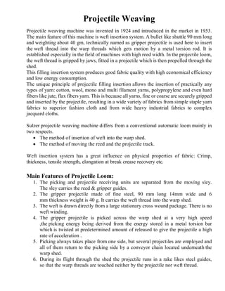
Projectiles and its types with dimension:
There are various projectile versions: Made of steel 9 cm long and 40 gm heavy with
small cross section suitable for yarns of fine to medium count.
Made of steel 9 cm long and 60 gm heavy with large cross section suitable for machines
with high width reed or for bulky yarns i.e, when fancy yarns are used.
Generally projectiles are made of steel or carbon composites with different variations. The
popularity of carbon composite projectiles has been declining due to their poor fatigue
performance compared to steel projectiles. D1 is the standard steel projectile for the vast
majority of commercial yarns. D12 is the same as D1 with a larger yarn clamping surface
to ensure more reliable gripping, even of delicate yarns. D2 has a big cross section and
large clamping surface and is used for extremely coarse yarns. K3 is the synthetic (carbon
composite) projectile which was intended to economically produce very delicate fabrics.
Projectile Guide: Two types of projectile guides: aligned guide teeth and staggered
guide teeth. Aligned guide teeth are used for applications such as bolting cloth, silk, fly
screen, coated glass, rain proof fabric, voile, linings and tape yarns. Staggered teeth are
Figure: Different types of projectiles
4. used for applications such as multifilament yarns, monofilament yarns, staple yarns
including terry, woolen yarns, hard fiber yarns and leno fabrics.
During reed beat-up the guide teeth emerge below the shed and release the filling yarn
through the upward facing opening.
Projectile Jaws:
1. Smooth
2. With groove
3. Crisscross knurls
4. With friction coating and lateral guidance
Figure: Projectile Guide
5. Picking/Filling insertion sequence (Insertion cycle of the projectile
machine):
A: Projectile 1 moves into the picking
position.
B: Projectile feeder 2 opens after
projectile 1 has gripped the filling end
presented to it.
C: The projectile has drawn the yarn
through the shed, while filling
tensioner lever 3 and adjustable filling
brake 4 act to minimize the strain
placed on the yarn during picking.
D: The projectile is braked by
projectile brake 8 in the receiving unit
and pushed back, while the filling
tensioner lever and the filling brake
hold the filling yarn lightly stretched.
At the same time, the projectile feeder
moves close to the selvage.
E: Projectile feeder 2 takes over the
filling yarn, while filling end grippers
5 hold it at both sides of the fabric.
6. F: The yarn is released by the
projectile on the receiving side. Filling
cutter 6 cuts the filling yarn.
A conveyor takes expelled projectile 1
and carries it outside the shed back to
the picking position.
G: The reed has beaten up the pick.
Tucking needles 7 tuck the filling tails
into the next shed (tucked selvage).
Filling tensioner lever 3 has taken up
the length of yarn remaining when
projectile feeder 2 returns. The next
projectile 1 is brought into the picking
position.
Hints: 1-Projectile, 2- Projectile Feeder, 3-Weft Tensioner Lever, 4-Weft Brake,
5-Weft End Gripper, 6-Weft Cutter, 7-Tucking Needles, 8-Projectile Brake.
7. Figure: Weft insertion with projectile
Figure: Dwell during the filling insertion of different weaving machine for different
width.
8. Torsion bar picking mechanism:
Working principle:
A strain energy is developed by twisting the torsion bar and released suddenly to
transfer the maximum possible strain-energy to the projectile before the projectile leaves
the picker-shoe.
Projection velocity of the weft carrier can be increased
1. By increasing the angle of twist.
2. By maintaining the same angle of twist on a larger diameter rod.
Weft is withdrawn from the package through a tension device, weft tensionar, shuttle
feeder, scissor, and weft end gripper. The picking arm released the projectile which is
shown in the guide teeth at the mid-shed position. At the receiving side the weft end gripper
is positioned to grip the weft after reception. Strain energy is developed in the bar and
released in such a way as to transfer the maximum possible strain energy to the projectile
before it separates from the picker shoe. The torsion bar (A) has its splined ends rigidly
constrained in an adjustable housing with provision for adjusting the maximum angle of
Hints: A=Torsion bar, B=Picking shaft, C=Picking lever, D=Picking shoe, E=Picking
shaft lever, F=Toggle plate, G=Antifriction bowl, H=Link, I=Picking cam, J=Shaft,
K=Bevel wheels, L=Oil brake, P=Projectile, R=Projectile guide.
Figure: Torsion bar (Projectile) picking mechanism.
9. twist and projectile initial velocity. The other end of the torsion rod is splined into the
picking lever (C) which carries the picking shoe (D) at its extremity. The projectile (P) is
illustrated in the shuttle lifter with the projectile spring opener. The bevel wheel (K) rotates
the picking cam shaft (J) which carries the picking cam (I). The picking shaft lever (E) is
rigidly connected to the torsion bar and through a short linkage to the toggle plate (F) center
at anti friction bowl (G).The action of the cam is for the small roller to bear against the
toggle rotate it anti clockwise about anti friction bowl (G), thus withdrawing the picking
shoe to its rearmost position. In this position the center of the toggle arrangement are in
line and the torsion bar is twisted to its predetermined angle. The nose of the picking cam
then bears against the roller carried between the toggle plates and moves the central pivot
of the toggle system off line center, thus permitting the strain energy in the rod to be
transmitted instantaneously to the projectile. The projectile separates from the shoe after
6.4 cm travel in 0.007 s as a velocity of about 24.4 m/s after being subjected to a maximum
acceleration of about 6700 m/s2 at a point 1.5 cm inboard of the rest position. The residual
energy in the picking system, some 62% of the whole is absorbed in the hydraulic buffer
the body and plunger of which are shown at (L).
Hints:
1-Picking shoe
2. Projectile
3. Projectile lifter
4. Tension flange
5. Knee joint
6. Roller lever
7. Oil brake
8. Cam
9. Torsion rod
10. Picking shaft
11. Picking lever
12. Roller
Figure: Torsion bar (Projectile) picking mechanism.
10. Loading of the torsion bar:
a) Torsion bar 2 in rest, knee joint lever (4+5) in articulate position.
b) Loading phase
c) Torsion bar in tension and knee joint lever in stable position, before the
launching control by roller 7.
11. Air supported filling insertion:
Pre-acceleration of the filling with compressed air reduces the strain on the filling yarn.
Two part, staggered guiding teeth reduce the strain on warp and filling. Therefore, even
delicate yarns, such as those without twist or air-intermingled, can be used in the warp to
make fabrics of good quality. With the air supported filling insertion, the peak values of
the tensile stress, which the filling yarns are subjected to, are reduced to a degree that
permits insertion of low tenacity yarns even at the highest speeds. Due to the support
provided by the compressed air, the flow of the tensile load phase is markedly softer and
the peak values of the tensile stress are reduced by approximately 50%. This allows
weaving of fine yarns.
Selvedge formation:
The tucking unit or intermediate tucking unit of the projectile weaving machine forms clean
tucked-in selvages. Because of the filling insertion system, the filling yarn is of exactly the
right length and need not be shortened, as a result, there is no yarn wasted. The projectile
weaving machine can also be fitted with units to make leno or sealed selvages. The yarn
end is tucked in by the interaction of filling end gripper 1 and tucking needle 2. After filling
insertion, the filling end grippers seize the pick on the left and right of the reed. After the
1- Weft end gripper
2- Tucking needle
Figure: Selvage formation in projectile loom.
12. projectile gripper has opened in the receiving unit and the filling yarn has been cut on the
picking side, the sley moves towards reed beat-up. The filling end grippers with the
clamped yarn ends move forward with it at the same time. While the next pick is inserted,
the tucking needles pull the filling ends out of the filling end grippers and place them in
the newly formed shed. In the case of very filling -intensive styles or when weaving with
coarse filling yarn, a split selvage with half cross leno interlacing can be used. For synthetic
fabrics, a selvage sealing device can be used for severing the selvage. Intermediate tuck-in
units used between the fabric widths during multi-width weaving, form the tucked selvages
at the cloth width dividing lanes.