Trnasformer working
•
1 gefällt mir•76 views

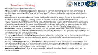
A transformer works on the principle of mutual induction to convert alternating current from one voltage to another. It consists of two coils - a primary coil and secondary coil - wound around an iron core. As current flows through the primary coil, it produces a changing magnetic field that induces a voltage in the secondary coil through electromagnetic induction. This allows electrical energy to be transferred between the coils without a direct connection. Transformers can step voltages up or down and are used widely in power transmission and distribution systems.

Empfohlen
Weitere ähnliche Inhalte
Was ist angesagt?
Was ist angesagt? (20)
Ähnlich wie Trnasformer working
Ähnlich wie Trnasformer working (20)
Mehr von Dr.Raja Masood Larik
Mehr von Dr.Raja Masood Larik (20)
Kürzlich hochgeladen
Kürzlich hochgeladen (20)
Trnasformer working
- 1. Transformer Working Lecture Notes by Dr.R.M.Larik 1 What is the working of a transformer? A transformer is an electrical apparatus designed to convert alternating current from one voltage to another. It can be designed to "step up" or "step down" voltages and works on the magnetic induction principle. A transformer is a passive electrical device that transfers electrical energy from one electrical circuit to another, or multiple circuits. A varying current in any one coil of the transformer produces a varying magnetic flux in the transformer's core, which induces a varying electromotive force across any other coils wound around the same core. Electrical energy can be transferred between separate coils without a metallic (conductive) connection between the two circuits. Faraday's law of induction. A transformer consists of two electrically isolated coils and operates on Faraday's principal of “mutual induction”, in which an EMF is induced in the transformers secondary coil by the magnetic flux generated by the voltages and currents flowing in the primary coil winding. The working principle of the single phase transformer is based on the Faraday's law of electromagnetic induction. Basically, mutual induction between two or more windings is responsible for transformation action in an electrical transformer. Basically, according to Electronics, a transformer is a device which is used to either raise or lower voltages and currents in an electrical circuit. In modern electrical distribution systems, transformers are used to boost voltage levels so as to decrease line losses during transmission. Magnetomotive force (mmf), Fm = NI ampere-turns (At), where N = number of conductors (or turns) and I = current in amperes.
- 2. Types of Transformer Lecture Notes by Dr.R.M.Larik 2 •Step Up Transformer and Step Down Transformer. •Three Phase Transformer and Single Phase Transformer. •Electrical Power Transformer, Distribution Transformer and Instrument Transformer. •Two Winding Transformer and Autotransformer. •Outdoor Transformer and Indoor Transformers. Uses of Transformer Step up for transmission of electricity Step down for distribution and utilization Single Phase for small scale applications (Toys, power supply) Three Phase use at Large scale (Transmission, Industrial etc) Power Transformer used in Electrical Grids for step up purposes usually rated in MVAs Distribution Transformer to fed 1-phase and 3-phase loads Instrument Transformer for relayin, protection metering purpose Autotransformer for dealing with EHV Indoor (present inside substation) covered area Outdoor distribution transformer (PMT)
- 3. Ampere Turns Magneto Motive Force Lecture Notes by Dr.R.M.Larik 3 Flux density is simply the total flux divided by the cross sectional area of the part through which it flows - B = Φ / Ae teslas. Thus 1 weber per square metre = 1 tesla. Flux density is related to field strength via the permeability. B = μ × H
- 4. Ideal transformer Lecture Notes by Dr.R.M.Larik 4 an an ideal transformer, it is assumed that entire amount of flux get linked with secondary winding (that is, no leakage flux). 100% efficiency: An ideal transformer does not have any losses like hysteresis loss, eddy current loss etc. So, the output power of an ideal transformer is exactly equal to the input power.
- 5. Single Phase Transformer working Lecture Notes by Dr.R.M.Larik 5
- 6. Leakage Flux of Transformer Lecture Notes by Dr.R.M.Larik 6
- 7. Core and Shell type Transformers Lecture Notes by Dr.R.M.Larik 7 In core type transformer both the primary and the secondary windings are placed on the side limbs whereas, in shell type transformer, the windings are placed on the central limbs of the transformer. The core type transformer has two magnetic circuits whereas the shell type transformer has one magnetic circuit. In core type transformer the core surrounds the windings whereas in shell type transformer the winding surrounds the core of the transformer.
- 8. Losses of transformer Lecture Notes by Dr.R.M.Larik 8
- 9. Hysteresis Loop Lecture Notes by Dr.R.M.Larik 9 Depends on material of core
- 10. Eddy current loss Lecture Notes by Dr.R.M.Larik 10 Depends on thickness of core
- 11. Power Transformer Lecture Notes by Dr.R.M.Larik 11 Used in Electrical Grids for large power handling
- 12. Distribution Transformer Lecture Notes by Dr.R.M.Larik 12 PMT (Pole Mounted Transformer) Used for utilization of electricity
- 13. Auto Transformer Lecture Notes by Dr.R.M.Larik 13 PMT (Auto Transformer where electrical isolation is not needed) Taps are available to obtain desired voltage