2. 2
DC GENERATOR WORKING PRINCIPLE
• An electric generator is based on the principle that whenever flux is cut by a
conductor, an e.m.f. is induced which will cause a current to flow if the
conductor circuit is closed.
• The direction of induced e.m.f. (and hence current) is given by Fleming’s
right hand rule.
• The essential components of a generator are:
a) a magnetic field
b) conductor or a group of conductors
c) motion of conductor w.r.t. magnetic field.
Lecture Notes by Dr.R.M.Larik
3. 3
DC GENERATOR WORKING PRINCIPLE (Contd.)
Simple Loop Generator
• Consider a single turn loop ABCD
rotating clockwise in a magnetic
field with a constant speed.
• As the loop rotates, the flux
linking the coil sides AB and CD
changes continuously.
• The e.m.f. induced in the coil
sides also changes but the e.m.f.
induced in one coil side adds to
that induced in the other side.
Lecture Notes by Dr.R.M.Larik
4. 4
DC GENERATOR WORKING PRINCIPLE (Contd.)
Action of Commutator
• Commutator is a cylindrical metal ring cut into two halves C1 and C2 separated
by insulation.
• The ends of coil sides AB and CD are connected to the segments C1 and C2.
• Two stationary carbon brushes, mounted on the commutator, carry current to
the external load R.
• The commutator always connects the coil side under S-pole to the +ve brush
and that under N-pole to the -ve brush.
Lecture Notes by Dr.R.M.Larik
5. 5
DC GENERATOR WORKING PRINCIPLE (Contd.)
Action of Commutator (Contd.)
• The purpose of brushes is to carry current from
the rotating winding to the stationary load.
• Variation of voltage across the brushes with the
angular displacement of the loop is not a steady
direct voltage but is pulsating.
• The voltage appearing across the brushes
varies from zero to maximum value and back to
zero twice for each revolution of the loop.
• The steady direct voltage can be obtained by using a large number of coils
connected in series, known as armature winding.
Lecture Notes by Dr.R.M.Larik
6. 6
DC MACHINE CONSTRUCTION AND ARMATURE WINDING
• A d.c. generator can be run
as a d.c. motor and vice-
versa.
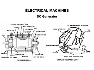
• Principal components of d.c.
machines are field, armature
core, armature winding,
commutator, and brushes
DC GENERATOR CONSTRUCTION
Field system
• Function of the field is to produce uniform magnetic flux.
• It consists of a number of salient poles bolted to the inside of circular frame (yoke).
Lecture Notes by Dr.R.M.Larik
7. 7
DC GENERATOR CONSTRUCTION (Contd.)
• Yoke is made of solid cast steel whereas the
pole pieces are composed of stacked
laminations.
• Field coils are mounted on the poles and
carry the d.c. exciting current.
• The coils are connected in such a way that
adjacent poles have opposite polarity.
• The m.m.f. developed by field coils produces
magnetic flux that passes through the pole
pieces, air gap, armature and the frame.
Field system (Contd.)
• D.C. machines have air gaps ranging from 0.5 mm to 1.5 mm.
• Since armature and field are composed of materials that have high permeability,
most of the m.m.f. of field coils is required to set up flux in the air gap.
Lecture Notes by Dr.R.M.Larik
8. 8
DC GENERATOR CONSTRUCTION (Contd.)
• Armature core is fixed to the machine shaft and rotates between the field poles.
• It consists of slotted soft-iron laminations (about 0.4 to 0.6 mm thick) that are
stacked to form a cylindrical core.
• The laminations are coated with a thin insulating film so that they do not make
electrical contact with each other.
Armature core
Lecture Notes by Dr.R.M.Larik
9. 9
DC GENERATOR CONSTRUCTION (Contd.)
• Purpose of laminating the core is to reduce the eddy current loss.
• The laminations are slotted to accommodate and secure the armature
winding and to give shorter air gap for the flux to cross between the pole face
and the armature “teeth”.
Armature core (Contd.)
Armature winding
• Slots of armature core hold insulated conductors that are connected in a
suitable manner.
• Armature conductors are connected in series to increase the voltage and in
parallel to increase the current.
• Armature winding of a d.c. machine is a closed-circuit winding; the
conductors being connected in a symmetrical manner forming a closed loop
or series of closed loops.
Lecture Notes by Dr.R.M.Larik
10. 10
DC GENERATOR CONSTRUCTION (Contd.)
• Commutator is a mechanical rectifier which converts the alternating voltage
generated in the armature winding into direct voltage across the brushes.
• Depending upon the manner the armature conductors are connected to the
commutator segments, there are two types of armature winding in a d.c.
machine
a) lap winding
b) wave winding.
Commutator
Brushes
• Purpose of the brushes is to ensure electrical connections between the
rotating commutator and stationary external load circuit.
• The brushes are made of carbon and rest on the commutator.
• The brush pressure is adjusted by means of adjustable springs
Lecture Notes by Dr.R.M.Larik
11. 11
DC GENERATOR CONSTRUCTION (Contd.)
Brushes (Contd.)
• If the brush pressure is very large, friction produces heat.
• If brush pressure is too weak, contact produces excessive sparking.
• Multipole machines have as many brushes as they have poles.
• Successive brushes round the commutator have +ve and -ve polarities.
• Brushes having the same polarity are connected together
Lecture Notes by Dr.R.M.Larik
12. 12
D.C. MACHINE ARMATURE WINDING
• A d.c. machine consists of windings distributed in slots over the outer
periphery of the armature core.
• Each conductor lies at right angles to the magnetic flux and to the direction of
its movement.
• The induced e.m.f. in the conductor is given by:
e = B l v volts
where B = magnetic flux density in Wb/m2
l = length of the conductor in metres
v = velocity (in m/s) of the conductor
Lecture Notes by Dr.R.M.Larik
13. 13
DC MACHINE ARMATURE WINDING (Contd.)
• DC machine consists of windings
distributed in slots over the outer
periphery of the armature core.
• The conductors are connected to form
coils.
• Basic component of all types of armature
windings is the armature coil.
• A single-turn coil has two conductors or
coil sides connected at the back of the
armature.
• A 4-turn armature coil has 8 conductors.
Lecture Notes by Dr.R.M.Larik
14. 14
DC MACHINE ARMATURE WINDING (Contd.)
• One coil side is placed under N-pole
and the other coil side under the next
S-pole at the corresponding position
and the e.m.f.s of the coil sides add
together.
• If the e.m.f. induced in one conductor
is 2.5 volts, then the e.m.f. of a
single-turn coil will be = 2 x 2.5 = 5
volts.
• For the same flux and speed, the
e.m.f. of a 4-turn coil will be = 8 x 2.5
= 20 V
Lecture Notes by Dr.R.M.Larik
15. 15
DC MACHINE ARMATURE WINDING (Contd.)
• D.C. armature windings are double
layer windings.
• One coil side lies at the top of a slot
and the other coil side lies at the
bottom of some other slot.
• The coil sides are nearly a pole pitch
apart and are numbered in order.
• In connecting the coils, it is ensured
that top coil side is joined to the
bottom coil side and vice-versa.
Lecture Notes by Dr.R.M.Larik
16. 16
DC MACHINE ARMATURE WINDING (Contd.)
• The coil sides are connected through
commutator segments in a manner
to form a series-parallel system
• A number of conductors are
connected in series so as to increase
the voltage and two or more such
series-connected paths in parallel to
share the current.
• Full lines represent top coil sides and
dotted lines represent the bottom coil
sides.
Lecture Notes by Dr.R.M.Larik
17. 17
DC MACHINE ARMATURE WINDING (Contd.)
• It is the number of commutator segments
spanned by each coil of the winding and is
denoted by YC.
• If one side of the coil is connected to
commutator segment 1 and the other side is
connected to commutator segment 2 then the
commutator pitch YC will be 1.
Commutator Pitch (YC)
Lecture Notes by Dr.R.M.Larik
18. 18
DC MACHINE ARMATURE WINDING (Contd.)
• If one side of the coil is connected
to commutator segment 1 and the
other side to commutator
segment 8 then commutator pitch
YC = 8 – 1 = 7.
• Since each coil has two ends and
as two coil connections are joined
at each commutator segment,
then
Number of coils = Number of
commutator segments
Commutator Pitch (YC) (Contd.)
• If an armature has 30 conductors, the number of coils will be 30/2 = 15 and
the number of commutator segments is also 15.
Lecture Notes by Dr.R.M.Larik
19. 19
DC MACHINE ARMATURE WINDING (Contd.)
• It is the distance measured in terms of number of armature slots (or
armature conductors) per pole.
• If a 4-pole generator has 16 coils, then number of slots = 16.
Pole pitch =
16
4
= 4 slots
Also Pole pitch =
No. of conductors
No. of poles
=
16 𝑥 2
4
= 8 conductors
Pole-Pitch
Coil Span or Coil Pitch (YS)
• It is the distance measured in terms of the number of armature slots (or
armature conductors) spanned by a coil.
• If one side of the coil is in slot 1 and the other in slot 10 the coil span
will be 9 slots.
Lecture Notes by Dr.R.M.Larik
20. 20
DC MACHINE ARMATURE WINDING (Contd.)
• The coil-span or coil pitch is equal to pole pitch.
• In such case, the e.m.f.s in the coil sides are
additive and have a phase difference of 0°.
• The e.m.f. induced in the coil is maximum.
• Generally the coil span is kept one pole pitch
Full-Pitched Coil
Fractional pitched coil
• The coil span or coil pitch is less than the pole pitch
• The phase difference between the e.m.f.s in the
two coil sides is not zero so the e.m.f. of the coil is
less compared to full-pitched coil.
Lecture Notes by Dr.R.M.Larik
21. 21
TYPES OF D.C. ARMATURE WINDINGS
Armature coils in a d.c. armature winding are connected in series with each other
in a manner that the generated voltages of the respective coils are added
together in the production of the terminal e.m.f.
Lap Winding
• Commutator pitch YC = 1 and coil span
YS ~ pole pitch.
• The ends of any coil are brought out to
the adjacent commutator segments
• All the coils of the armature are in
sequence with the last coil connected to
the first coil.
• Consequently, closed circuit winding
results.
Lecture Notes by Dr.R.M.Larik
22. 22
TYPES OF D.C. ARMATURE WINDINGS (Contd.)
Wave Winding
• The commutator pitch YC ~ 2 pole
pitches and coil span = pole pitch.
• The coils under consecutive pole pairs
are joined together in series to get their
e.m.f.s added.
• After passing once around the armature,
the winding falls in a slot to the left or
right of the starting point and thus
connecting up another circuit.
• Thus, all the conductors are connected in a single closed winding.
• It is called wave winding because of the wavy appearance of the end
connections.
Lecture Notes by Dr.R.M.Larik
23. 23
Expression for the e.m.f. generated in a d.c. generator is as under.
Let
Φ = flux/ pole in Wb
Z = total number of armature conductors
P = number of poles
A = number of parallel paths = 2 ... for wave winding
= P ... ………………………………for lap winding
N = speed of armature in r.p.m.
Eg = e.m.f. of the generator = e.m.f./ parallel path
Flux cut by one conductor in one revolution of the armature,
dΦ = PΦ Webers
N/60 = speed of armature in r.p.s.
Time taken to complete one revolution,
dt = 60/N second
E.M.F. Equation of a D.C. Generator
DC GENERATOR WORKING PRINCIPLE (Contd.)
Lecture Notes by Dr.R.M.Larik
24. 24
DC GENERATOR WORKING PRINCIPLE (Contd.)
e.m.f generated/conductor =
dϕ
dt
=
P ϕ
Τ60 N
=
P ϕ N
60
volt
e.m.f. of generator,
Eg = e.m.f. per parallel path
= (e.m.f/conductor) x No. of conductors in series per parallel path
=
PΦ N
60
x
Z
A
=
Φ Z N
60
x
P
A
where A = 2 for-wave winding
= P for lap winding
E.M.F. Equation of a D.C. Generator (Contd.)
Lecture Notes by Dr.R.M.Larik
25. 25
DC GENERATOR WORKING PRINCIPLE (Contd.)
Problem 1(a):
A four-pole generator, having wave-wound armature winding has 51
slots, each slot containing 20 conductors. What will be the voltage
generated in the machine when driven at 1500 rpm assuming the flux
per pole to be 7.0 mWb ?
Solution:
P = 4, Φ = 7x10⁻³ Wb, Z = 51x20 = 1020, A = 2 (for wave winding),
N = 1500 r.p.m.
Eg ?
E.m.f of generator Eg =
Φ Z N
60
x
P
A
=
7x10−3x 1020 x 1500
60
x
4
2
= 357 VLecture Notes by Dr.R.M.Larik
26. 26
DC GENERATOR WORKING PRINCIPLE (Contd.)
Problem 1(b)
A 6-pole lap-wound d.c. generator has 600 conductors on its
armature. The flux per pole is 0.02 Wb. Calculate the speed at which
the generator must be run to generate 300V. What would be the
speed if the generator were wave-wound?
Problem 1(c): An 8-pole, lap-wound armature rotated at 350 r.p.m. is
required to generate 260V. The flux per pole is 0.05 Wb. If the
armature has 120 slots, calculate the number of conductors per slot.
Solution:
P = 8, Φ = 0.05 Wb/pole, Slots = 120, Eg = 260 V dc., N = 350 r.p.m.
No. of conductors per slot ?
Eg =
Φ Z N
60
x
P
A
Lecture Notes by Dr.R.M.Larik
27. 27
DC GENERATOR WORKING PRINCIPLE (Contd.)
Problem 1(c)
Solution (Contd.):
Z =
Eg x 60 A
P Φ N
=
260 x 60 x 8
8 x 0.05 x 350
= 890
No of conductors/ slot =
890
120
= 7.41
The value must be an even number. Hence, conductors/ slot = 8
Problem 1(d)
The armature of a 6-pole, 600 r.p.m. lap-wound d.c. generator has 90
slots. If each coil has 4 turns, calculate the flux per pole required to
generate an e.m.f. of 288V.
Lecture Notes by Dr.R.M.Larik
28. 28
TYPES OF D.C. GENERATORS
Generators are classified according to the methods of field excitation.
− Separately excited d.c. generators
− Self-excited d.c. generators
• A d.c. generator whose field magnet winding is supplied from an independent
external d.c. source is called a separately excited generator.
• The voltage output depends upon the speed of rotation of armature and the
field current (Eg = PΦZN/ 60 A).
• The greater the speed and field current, greater is the generated e.m.f.
• Separately excited d.c. generators are rarely used in practice.
Separately Excited D.C. Generators
Lecture Notes by Dr.R.M.Larik
29. 29
TYPES OF D.C. GENERATORS (Contd.)
Separately Excited D.C. Generators
Armature current, Ia = IL
Terminal voltage, V = Eg – IaRa
Electric power developed = Eg Ia
Power delivered to load = Eg Ia – Ia
2 Ra = Ia (Eg – IaRa) = VIa
Lecture Notes by Dr.R.M.Larik
30. 30
TYPES OF D.C. GENERATORS (Contd.)
Self-Excited D.C. Generators
• A d.c. generator whose field winding is supplied current from the output of the
generator itself is called a self-excited generator.
• There are three types of self-excited generators depending upon the manner
the field winding is connected to the armature
i) Shunt generator
ii) Series generator
iii) Compound generator
Lecture Notes by Dr.R.M.Larik
31. 31
TYPES OF D.C. GENERATORS (Contd.)
Self-Excited D.C. Generators (Contd.)
➢Shunt Generator
• In a shunt generator, the field winding is connected in parallel with the
armature winding so that terminal voltage of the generator is applied across it.
• The shunt field winding has many turns of fine wire having high resistance.
• Part of armature current flows through shunt field winding and the rest flows
through the load.
Shunt field current, Ish =
V
Rsh
Armature current, Ia = IL + Ish
Terminal voltage, V = Eg – IaRa
Power developed in armature = Eg Ia
Power delivered to load = V IL
Lecture Notes by Dr.R.M.Larik
32. 32
TYPES OF D.C. GENERATORS (Contd.)
Self-Excited D.C. Generators (Contd.)
➢Series generator
• In a series wound generator, the field winding is connected in series with
armature winding so that whole armature current flows through the field
winding as well as the load.
• Since the field winding carries the whole
of load current, it has a few turns of thick
wire having low resistance.
Power delivered to load = EgIa – Ia
2(Ra + Rse) = Ia[Eg – Ia(Ra + Rse)] = VIa or VIL
Armature current, Ia = Ise = IL = I (say)
Terminal voltage, V = Eg – I (Ra + Rse)
Power developed in armature = Eg Ia
Power delivered to load
Lecture Notes by Dr.R.M.Larik
33. 33
TYPES OF D.C. GENERATORS (Contd.)
Self-Excited D.C. Generators (Contd.)
➢Compound generator
There are two field windings on each pole - one is in series and the other in parallel
with the armature. A compound wound generator may be:
- Short Shunt with shunt field winding in parallel with the armature winding.
- Long Shunt with shunt field winding in parallel with both series field and armature
Short Shunt
Series field current, Ise = IL
Shunt field current, Ish =
V + Ise Rse
Rsh
Terminal voltage, V = Eg – IaRa – IseRse
Power developed in armature = Eg Ia
Power delivered to load = V IL
Lecture Notes by Dr.R.M.Larik
34. 34
TYPES OF D.C. GENERATORS (Contd.)
➢Compound generator (Contd.)
Long Shunt
Series field current, Ise = Ia = IL + Ish
Shunt field current, Ish =
V
Rsh
Terminal voltage, V = Eg – Ia (Ra + Rse)
Power developed in armature = Eg Ia
Power delivered to load = V IL
Lecture Notes by Dr.R.M.Larik
35. 35
TYPES OF D.C. GENERATORS (Contd.)
Problem 2(a)
A shunt generator delivers 450 A at 230 V and the resistance of the
shunt field and armature are 50 Ω and 0.03 Ω respectively. Calculate
the generated e.m.f.
Solution
IL = 450 A, Output voltage = 230 V, Rsh = 50 Ω, Ra = 0.03 Ω
Eg ?
Ish =
V
Rsh
=
230
50
= 4.6A
Ia = IL + Ish = 450 + 4.6 = 454.6 A
Armature voltage drop = Ia Ra
= 454.6 x 0.03 = 13.6 V
Eg = V + Ia Ra = 230 + 13.6
= 243.6 V Lecture Notes by Dr.R.M.Larik
36. 36
TYPES OF D.C. GENERATORS (Contd.)
Problem 2(b)
A 100 kW, 240 V shunt generator has a field resistance of 55 and
armature resistance of 0.067 . Find the full load generated voltage.
Problem 2(c)
A 4-pole d.c. shunt generator with a wave-wound armature has to
supply a load of 500 lamps each of 100 W at 250 V. Allowing 10 V for
the voltage drop in the connecting leads between generator and the
load and a drop of 1 V per brush, calculate the speed at which the
generator should be driven. The flux per pole is 30 mWb and the
armature and shunt field resistances are 0.05 and 65
respectively. The number of armature of armature conductors is 390.
Solution
P = 4, wave wound load = 500 lamps of 100 W each, Output
voltage = 250 V, connecting leads voltage drop = 10 V,
Lecture Notes by Dr.R.M.Larik
37. 37
TYPES OF D.C. GENERATORS (Contd.)
Problem 2(c)
Solution (Contd.)
Brush voltage drop = 1 V/ brush, Φ = 30 mWb, Ra = 0.05 Ω, Rsh = 65 Ω,
A = 2, Z = 390
N ?
Load current IL =
500 x 100
250
= 200 A
Voltage across shunt = 250 + 10 = 260 V
Ish =
V
Rsh
=
260
65
= 4A
Ia = IL + Ish = 200 + 4 = 204 A
Brush voltage drop (total) = 2 x 1 = 2 V
Lecture Notes by Dr.R.M.Larik
38. 38
TYPES OF D.C. GENERATORS (Contd.)
Problem 2(c)
Solution (Contd.):
Eg = Supply voltage V + brush voltage drop + Ia Ra
= 260 + 2 + 204 x 0.05 = 272.2 V
Also Eg =
Φ Z N
60
x
P
A
N =
Eg x 60 A
PΦZ
=
272.2 x 60 x 2
4 x 30 x10−3 x 390
= 698 r.p.m.
Lecture Notes by Dr.R.M.Larik
39. 39
TYPES OF D.C. GENERATORS (Contd.)
Problem 2(d)
An 8-pole d.c. shunt generator with 778 wave-connected armature
conductors and running at 500 r.p.m. supplies a load of 12.5 Ω
resistance at terminal voltage of 250 V. The armature resistance is
0.24 Ω and the field resistance is 250 Ω. Find the armature current, the
induced e.m.f. and the flux per pole.
Problem 3
A separately excited d.c. generator when running at 1200 r.p.m.
supplies 200 a at 125 V to a circuit of constant resistance. What will be
the load current when the speed is dropped to 1000 r.p.m. if the field
current is unaltered? Armature resistance is 0.04 and voltage drop at
brushes is 2 V.
Lecture Notes by Dr.R.M.Larik
40. 40
TYPES OF D.C. GENERATORS (Contd.)
Problem 3
Solution
N1 = 1200 r.p.m, IL = 200 A, Output voltage = 125 V, N2 = 1000 r.p.m,
Ra = 0.04 Ω, total brush voltage drop = 2 V
IL ? (at 1000 r.p.m. with field current unaltered),
Load resistance RL =
V
IL
=
125
200
= 0.625 Ω
Eg1 = V + IL Ra + brush voltage drop
= 125 + 200 x 0.04 +2
= 135 V
Eg2
Eg1
=
N2
N1
Lecture Notes by Dr.R.M.Larik
41. 41
TYPES OF D.C. GENERATORS (Contd.)
Problem 3
Solution (Contd.):
Eg2 = Eg1 x
N2
N1
= 135 x
1000
1200
= 112.5 V
Voltage across series combination of RL and Ra
V′
= Eg2 – brush voltage drop
= 112.5 – 2 = 110.2 V
New load current
IL
′
=
V′
Ra+ RL
=
110.5
0.04+0.625
= 166 A
Lecture Notes by Dr.R.M.Larik
42. 42
TYPES OF D.C. GENERATORS (Contd.)
Problem 4
A long-shunt compound generator delivers a load current of 50 A at 500
V and has armature, series field and shunt field resistances of 0.05 ,
0.03 and 250 respectively. Calculate the generated voltage and the
armature current. Allow 1 V per brush for contact drop.
Solution
IL = 50 A, Output voltage = 500 V,
Ra = 0.05 Ω, Rse = 0.03 Ω,
Rsh = 250 Ω, brush voltage drop =
1V/brush
Eg ?, Ia ?
Ish =
V
Rsh
=
500
250
= 2 A
Lecture Notes by Dr.R.M.Larik
43. 43
TYPES OF D.C. GENERATORS (Contd.)
Problem 4
Solution (Contd.):
Current through armature and
series winding
Ia = IL + Ish = 50 + 2 = 52 A
Voltage drop in series field
IaRse = 52 x 0.03 = 1.56 V
Armature voltage drop
IaRa = 52 x 0.05 = 2.6 V
Brush voltage drop = 2 x 1 = 2 V
Eg = V + Ia Ra + IaRse + brush voltage drop
= 500 + 2.6 + 1.56 + 2 = 506.16 V
Lecture Notes by Dr.R.M.Larik
44. 44
TYPES OF D.C. GENERATORS (Contd.)
Problem 5
A short-shunt compound generator delivers a load current of 30 A at
220 V, and has armature, series-field and shunt-field resistances of
0.05 Ω, 0.30 Ω and 200 Ω respectively. Calculate the induced e.m.f.
and the armature current. Allow 1.0 V per brush for contact drop.
Lecture Notes by Dr.R.M.Larik
45. 45
LOSSES IN A D.C. MACHINE
➢Copper losses
Brush contact loss is included in armature copper loss.
➢Iron or Core losses
The core losses occur in the armature and are due to rotation of armature in
the magnetic field of the poles.
These losses are of two types
• Hysteresis loss
• Eddy current loss
a) Armature copper loss = Ia
2
Ra
b) Shunt field copper loss = Ish
2
Rsh
c) Series field copper loss = Ise
2
Rse
Lecture Notes by Dr.R.M.Larik
46. 46
LOSSES IN A D.C. MACHINE (Contd.)
➢Iron or Core losses (Contd.)
✓ Hysteresis loss
• The loss occurs in the armature since
any given part of the armature core is
subjected to magnetic field reversals
as it passes under successive poles.
• When the piece ab is under N-pole,
the magnetic lines pass from a to b.
• Half a revolution later, the same piece
of iron is under S-pole and magnetic
lines pass from b to a so that
magnetism in the iron is reversed.
Lecture Notes by Dr.R.M.Larik
47. 47
LOSSES IN A D.C. MACHINE (Contd.)
➢Iron or Core losses
✓ Hysteresis loss
For continuous reversing of molecular magnets in the armature core,
some power has to be spent, called hysteresis loss, as given by
Steinmetz formula.
Bmax = Maximum flux density in armature
f = Frequency of magnetic reversals
= NP/120 where N is speed in r.p.m. & P is the number of poles
V = Volume of armature in m3
η = Steinmetz hysteresis co-efficient (varies with type of material)
To reduce the loss, armature core is made of silicon steel having low
value of η.
Hysteresis loss, Ph = η Bmax
1.6 f V watts
Lecture Notes by Dr.R.M.Larik
48. 48
LOSSES IN A D.C. MACHINE (Contd.)
➢Iron or Core losses
✓ Eddy current loss
• Voltages induced in the armature core
produce circulating (eddy) currents
causing power loss.
• In a core made of solid iron lump, the
resistance to eddy current will be very
low due to large cross-sectional area,
hence, the eddy current will be higher.
• Eddy current can be reduced by making
core resistance as high as practical by
constructing the core of thin iron
laminations insulated from each other
with a coating of varnish.
Lecture Notes by Dr.R.M.Larik
49. 49
LOSSES IN A D.C. MACHINE (Contd.)
➢Iron or Core losses (Contd.)
✓ Eddy current loss
Bmax = Maximum flux density in Wb/m2
f = Frequency of magnetic reversals in Hz
t = Thickness of lamination in m
V = Volume of core in m3
where Ke = Constant depends on the electrical resistance of core
➢Mechanical losses
These losses are classified as:
i) Friction loss e.g., bearing friction, brush friction etc.,
ii) Windage loss i.e., air friction of rotating armature and depends upon the
speed of the machine.
Eddy current loss, Pe = Ke Bmax
2 f2 t2 V watts
Lecture Notes by Dr.R.M.Larik
50. 50
CONSTANT AND VARIABLE LOSSES
➢Constant losses
a) Iron losses,
b) Mechanical losses,
c) Shunt field losses
➢Variable losses
The variable losses, vary with load, are:
a) Copper loss in armature winding (Ia
2 R ),
b) Copper loss in series field winding (Ise
2 R )
Total losses = Constant losses + Variable losses
Field Cu loss is constant for shunt and compound generators.
Lecture Notes by Dr.R.M.Larik
51. 51
POWER STAGES AND EFFICIENCY (Contd.)
Various power stages in a d.c. generator are represented diagrammatically
A - B = Iron and friction losses
B - C = Copper losses
Mechanical efficiency
Electrical efficiency
Commercial or overall efficiency
ηm =
B
A
=
Eg Ia
Mechanical power input
ηe =
C
B
=
V IL
Eg Ia
ηc =
C
A
=
V IL
Mechanical power input
Lecture Notes by Dr.R.M.Larik
52. 52
POWER STAGES AND EFFICIENCY (Contd.)
Problem 6(a)
A shunt generator supplies 96 A at a terminal voltage of 200 V. The
armature and shunt field resistances are 0.1 Ω and 50 Ω respectively.
The iron and frictional losses are 2500 W. Find (i) e.m.f. generated
(ii) copper losses (iii) commercial efficiency.
Solution
IL = 96 A, Output voltage VL = 200 V,
Ra = 0.1 Ω, Rsh = 50 Ω, iron &
frictional losses = 2500 W
Eg ? Cu loss ? ηc ?
i) Ish =
V
Rsh
=
200
50
= 4 A
Ia = IL + Ish = 96 + 4 = 100 A
Lecture Notes by Dr.R.M.Larik
53. 53
POWER STAGES AND EFFICIENCY (Contd.)
Problem 6(a)
Solution (Contd.)
Eg = V + Ia Ra
(neglecting brush drop)
= 200 + 100 x 0.1 = 210 V
ii) Armature Cu loss = Ia
2 Ra
= (100)2 x 0.1 = 1000 W
Shunt Cu loss = Ish
2
Rsh
= (4)2 x 50 = 800 W
Total Cu loss = 1000 + 800 = 1800 W
iii) Total loss = Rotational loss + Cu loss
= 2500 + 1800 = 4300 W
Lecture Notes by Dr.R.M.Larik
54. 54
POWER STAGES AND EFFICIENCY (Contd.)
Problem 6(a)
Solution (Contd.)
Output power = IL
′
x VL
= 96 x 200 = 19200 W
Input power = 19200 + 4300
= 23500 W
ηc =
Output power
Input power
=
19200
23500
x 100 = 81.7 %
Problem 6(b): A shunt generator delivers full load current of 200 A at
240 V. The shunt field resistance is 60 Ω and full load efficiency is
90%. The rotational losses are 800 W. Find (i) armature current (ii)
current at which maximum efficiency occurs.
Lecture Notes by Dr.R.M.Larik
55. 55
ARMATURE REACTION
• Current flowing through armature conductors creates a magnetic flux (armature
flux), distorting and weakening the poles (main) flux, is called armature reaction.
• When the generator is on no-load, a small current flowing in the armature
does not appreciably affect the main flux Ф1
• When the generator is loaded, the current flowing through armature
conductors sets up flux Ф2
• By superimposing Ф1 and Ф2, resulting flux Ф3 is produced
Lecture Notes by Dr.R.M.Larik
56. 56
ARMATURE REACTION (Contd.)
• The flux density is increased at the trailing pole tip (point B) and decreased at
the leading pole tip (point A).
• The unequal field distribution causes:
a) Distortion in main flux
b) Saturation sets in due to higher flux density at pole tip B
• Increase in flux at pole tip B is less than the decrease in flux under pole tip A,
hence, flux Ф3 at full load is less than flux Ф1 at no load.
Geometrical Neutral Axis
Geometrical Neutral Axis (G.N.A.) is a
line that bisects the angle between the
centre line of adjacent poles
Lecture Notes by Dr.R.M.Larik
57. 57
CHARACTERISTICS OF D.C. GENERATORS
➢ No-load Saturation Characteristic (Eo/If)
• Also known as Magnetic Characteristic or Open-circuit Characteristic
(O.C.C.) and shows the relation between the no-load generated e.m.f. in
armature, Eo and the field current If at a given fixed speed.
• The shape is practically the same for all generators whether separately-
excited or self-excited.
➢ Internal or Total Characteristic (E/Ia)
It gives the relation between the e.m.f. E actually induces in the armature
and the armature current Ia.
➢ External Characteristic (V/I)
• It gives relation between terminal voltage V and the load current I.
• Values of V are obtained by subtracting IaRa and carbon brushes voltage drops
from corresponding values of E.
Lecture Notes by Dr.R.M.Larik
58. 58
CHARACTERISTICS OF A SEPARATELY EXCITED
D.C. GENERATOR
➢Open Circuit Characteristic
• The field current If is obtained from an external independent d.c. source
which can be increased from zero to the rated value.
• When the field current is zero, the residual magnetism in the poles will
generate small initial e.m.f.
• The voltage equation of a d.c. generator is: Eg =
ϕ Z N
60
x
P
A
volt
Lecture Notes by Dr.R.M.Larik
59. 59
CHARACTERISTICS OF A SEPARATELY EXCITED
D.C. GENERATOR
➢Internal and External Characteristics
The external characteristic of a separately excited generator is the curve
between the terminal voltage V and the load current IL (armature current).
Lecture Notes by Dr.R.M.Larik
60. 60
CHARACTERISTICS OF A SEPARATELY EXCITED
D.C. GENERATOR
➢Internal and External Characteristics (Contd.)
As the load current increases, the terminal voltage falls because:
a) The armature reaction
weakens the main flux so
the actual e.m.f.
generated E on load is
less than the no load
generator voltage Eo.
b) There is voltage drop
across armature
resistance (= ILRa = IaRa).
Lecture Notes by Dr.R.M.Larik
61. 61
CHARACTERISTICS OF A SEPARATELY EXCITED
D.C. GENERATOR
➢Internal and External Characteristics (Contd.)
• The internal characteristic can be determined from external
characteristic by adding ILRa drop to the external characteristic because
armature reaction drop is included in the external characteristic.
• Curve 2 is the internal characteristic of the generator and lies above the
external characteristic.
Lecture Notes by Dr.R.M.Larik
62. 62
VOLTAGE BUILD-UP IN A SELF-EXCITED GENERATORS
➢Shunt Generator
• If the generator is run, some e.m.f. will be
generated due to residual magnetism in the
main poles circulating a field current which
produces additional flux.
• The process continues and the generator
builds up the normal generated voltage
following the O.C.C.
• The field resistance Rf can be represented by
a straight line passing through the origin.
• The two curves can be shown on the same
diagram as they have the same ordinate
Lecture Notes by Dr.R.M.Larik
63. 63
VOLTAGE BUILD-UP IN A SELF-EXCITED GENERATORS
➢Shunt Generator (Contd.)
• The rate at which the current increases
depends upon the voltage available for
increasing it.
• Suppose at any instant, the field current is
i (= OA) and is increasing at the rate di/dt.
Then, Eo = i Rf + L
𝑑𝑖
𝑑𝑡
where Rf = total field circuit resistance
L = inductance of field circuit
• The generated e.m.f. has to supply the ohmic drop i Rf in the winding and to
overcome the opposing self-induced e.m.f. in the field coil i.e. L(di/ dt)
Lecture Notes by Dr.R.M.Larik
64. 64
CHARACTERISTICS OF A SHUNT GENERATOR
The armature current Ia splits up into two parts; a small fraction Ish flowing
through shunt field winding while the major part IL goes to the external load.
➢O.C.C.
• Line OA represents the shunt field resistance.
• At no-load, the terminal voltage of the generator will be constant (= OM)
Lecture Notes by Dr.R.M.Larik
65. 65
CHARACTERISTICS OF A SHUNT GENERATOR (Contd.)
➢Internal characteristic
When the generator is loaded, flux per pole is reduced due to armature
reaction, hence, e.m.f. E generated on load is less than the e.m.f.
generated at no load resulting in slight drop in the the internal
characteristic (E/Ia)
➢External characteristic
It gives the relation between terminal voltage V and load current IL.
V = E - IaRa = E - (IL + Ish) Ra
Therefore, external characteristic curve will lie below the internal
characteristic curve by an amount equal to drop in the armature circuit.
Lecture Notes by Dr.R.M.Larik
66. 66
CHARACTERISTICS OF A SHUNT GENERATOR (Contd.)
Problem 7(a): The open-circuit characteristic of a d.c. shunt
generator driven at rated speed is as follows:
If resistance of field circuit is adjusted to 53 , calculate the open
circuit voltage and load current when the terminal voltage is 100 V.
Neglect armature reaction and assume an armature resistance of
0.1 .
Solution
Ra = 0.1 , Rsh = 53 , VL = 100 V
Open circuit voltage ? Load current ?
Shunt field current Ish =
V
Rsh
=
100
53
= 1.89 A
Corresponding OC voltage (at If = 1.89 A) Eg = 144 V
Field current (A) 0.5 1.0 1.5 2.0 2.5 3.0 3.5
E.M.F. (V) 60 120 138 145 149 151 152
Lecture Notes by Dr.R.M.Larik
67. 67
CHARACTERISTICS OF A SHUNT GENERATOR (Contd.)
Solution (Contd.)
Eg = VL + Ia Ra =144
= 100 + Ia x 0.1
Ia = 440 A
Lecture Notes by Dr.R.M.Larik
68. 68
CHARACTERISTICS OF SERIES GENERATOR
The load current and the exciting current are same.
➢ O.C.C.
Curve 1 shows the open circuit characteristic (O.C.C.)
Lecture Notes by Dr.R.M.Larik
69. 69
CHARACTERISTICS OF SERIES GENERATOR (Contd.)
➢Internal characteristic
➢ External characteristic
Curve 3 shows the external characteristic which gives the relation
between terminal voltage and load current IL.
• Curve 2, showing the internal characteristic, gives the relation between
the generated e.m.f. E on load and armature current.
• Due to armature reaction, the flux in the machine will be less than the flux
at no load, hence, e.m.f. E, generated under load conditions, will be less
than the e.m.f. Eo generated under no load conditions
• The internal characteristic curve lies below the O.C.C. curve.
V = E - Ia (Ra + Rse )
The external characteristic curve lies below internal characteristic curve by
an amount equal to ohmic drop in the machine.
Lecture Notes by Dr.R.M.Larik
70. 70
COMPOUND GENERATOR CHARACTERISTICS
➢ External characteristic
The compound generator can be cumulatively compounded or differentially
compounded generator.
• In a cumulatively compounded generator the series excitation aids the
shunt excitation.
• The external characteristics of long and short shunt compound
generators are almost identical.Lecture Notes by Dr.R.M.Larik
71. 71
COMPOUND GENERATOR CHARACTERISTICS (Contd.)
➢ External characteristic (Contd.)
• If series winding turns are so adjusted that with the increase in load current
the terminal voltage increases, it is called over-compounded generator.
• The increase in generated voltage is greater than the IaRa drop so that
instead of decreasing, the terminal voltage increases
• If series winding turns are so adjusted that with the increase in load
current, the terminal voltage substantially remains constant, it is called flat-
compounded generator.
• The full-load voltage is nearly equal to the no-load voltage
• If series field winding has lesser number of turns than for a flat
compounded machine, the terminal voltage falls with increase in load
current and such a machine is called under-compounded generator.
Lecture Notes by Dr.R.M.Larik
72. 72
VOLTAGE REGULATION
• The change in terminal voltage of a generator between full and no load (at
constant speed) is called the voltage regulation, usually expressed as a
percentage of the voltage at full-load.
% Voltage regulation =
VNL − VFL
VFL
x 100
where VNL = Terminal voltage of generator at no load
VFL = Terminal voltage of generator at full load
• Voltage regulation of a generator is determined with field circuit and the
speed is held constant.
• If the voltage regulation of a generator is 10%, it means that terminal
voltage increases 10% as the load is changed from full load to no load.
Lecture Notes by Dr.R.M.Larik