Basic Gates and Functions Introduction
•Als DOCX, PDF herunterladen•
2 gefällt mir•8,659 views

logic gates

Empfohlen
Weitere ähnliche Inhalte
Was ist angesagt?
Was ist angesagt? (20)
Andere mochten auch
Andere mochten auch (20)
Ähnlich wie Basic Gates and Functions Introduction
Ähnlich wie Basic Gates and Functions Introduction (20)
Kürzlich hochgeladen
Kürzlich hochgeladen (20)
Basic Gates and Functions Introduction
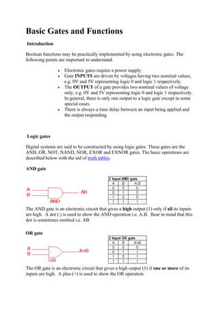
- 1. Basic Gates and Functions Introduction Boolean functions may be practically implemented by using electronic gates. The following points are important to understand. Electronic gates require a power supply. Gate INPUTS are driven by voltages having two nominal values, e.g. 0V and 5V representing logic 0 and logic 1 respectively. The OUTPUT of a gate provides two nominal values of voltage only, e.g. 0V and 5V representing logic 0 and logic 1 respectively. In general, there is only one output to a logic gate except in some special cases. There is always a time delay between an input being applied and the output responding. Logic gates Digital systems are said to be constructed by using logic gates. These gates are the AND, OR, NOT, NAND, NOR, EXOR and EXNOR gates. The basic operations are described below with the aid of truth tables. AND gate The AND gate is an electronic circuit that gives a high output (1) only if all its inputs are high. A dot (.) is used to show the AND operation i.e. A.B. Bear in mind that this dot is sometimes omitted i.e. AB OR gate The OR gate is an electronic circuit that gives a high output (1) if one or more of its inputs are high. A plus (+) is used to show the OR operation.
- 2. NOT gate The NOT gate is an electronic circuit that produces an inverted version of the input at its output. It is also known as an inverter. If the input variable is A, the inverted output is known as NOT A. This is also shown as A', or A with a bar over the top, as shown at the outputs. The diagrams below show two ways that the NAND logic gate can be configured to produce a NOT gate. It can also be done using NOR logic gates in the same way. NAND gate This is a NOT-AND gate which is equal to an AND gate followed by a NOT gate. The outputs of all NAND gates are high if any of the inputs are low. The symbol is an AND gate with a small circle on the output. The small circle represents inversion. NOR gate This is a NOT-OR gate which is equal to an OR gate followed by a NOT gate. The outputs of all NOR gates are low if any of the inputs are high. The symbol is an OR gate with a small circle on the output. The small circle represents inversion.
- 3. EXOR gate The 'Exclusive-OR' gate is a circuit which will give a high output if either, but not both, of its two inputs are high. An encircled plus sign ( ) is used to show the EOR operation. EXNOR gate The 'Exclusive-NOR' gate circuit does the opposite to the EOR gate. It will give a low output if either, but not both, of its two inputs are high. The symbol is an EXOR gate with a small circle on the output. The small circle represents inversion. The NAND and NOR gates are called universal functions since with either one the AND and OR functions and NOT can be generated. Note: A function in sum of products form can be implemented using NAND gates by replacing all AND and OR gates by NAND gates. A function in product of sums form can be implemented using NOR gates by replacing all AND and OR gates by NOR gates.
- 4. Table 1: Logic gate symbols Table 2 is a summary truth table of the input/output combinations for the NOT gate together with all possible input/output combinations for the other gate functions. Also note that a truth table with 'n' inputs has 2n rows. You can compare the outputs of different gates. Table 2: Logic gates representation using the Truth table