S7 bas-16
•Als PPT, PDF herunterladen•
2 gefällt mir•2,097 views

TREINAMENTO SIEMENS STEP 7 BASICO S7300/400

Empfohlen
Weitere ähnliche Inhalte
Was ist angesagt?
Was ist angesagt? (20)
Andere mochten auch
Andere mochten auch (14)
Ähnlich wie S7 bas-16
Ähnlich wie S7 bas-16 (20)
Mehr von confidencial
Mehr von confidencial (20)
Kürzlich hochgeladen
Kürzlich hochgeladen (20)
S7 bas-16
- 1. SIMATIC S7 Siemens Engenharia e Service 2002. Todos os direitos reservados. Data: 15/04/14 Arquivo: S7-Bas-16.1 Totally Integrated Automation SIMATIC WinCC SIMATIC PC SIMATIC DP SIMATIC Controller SIMATIC HMI SIMATIC NET SIMATIC PCS 7 SIMATIC Software SIMATIC
- 2. SIMATIC S7 Siemens Engenharia e Service 2002. Todos os direitos reservados. Data: 15/04/14 Arquivo: S7-Bas-16.2 Automating with SIMATIC S7 ASI PROFIBUS-DP S7-200 S7-300 S7-400 OP...OS 7 8 9 4 5 6 1 2 3 0 . D E F A B C I N S D E L S H IF T H E L P E S C E N T E R A C K S I M A T I C O P 1 7 S H IF T H E L PK 1 K 5 K 6 K 7 K 8K 2 K 3 K 4 K 9 K 1 0 K 1 1 K 1 2 K 1 3 K 1 4 K 1 5 K 1 6 F 1 F 5 F 6 F 7 F 8F 2 F 3 F 4 S I M A T I C O P 1 7 4 x 2 0 Z e i c h e n 6 / 1 1 m m S c h r i f t h ö h e 8 x 4 0 Z e i c h e n Z e i c h e n g r ö ß e n b e l i e b i g m i s c h b a r Standard Tools Engineering Tools Runtime Software SIMATIC SOFTWARE WIN CC PCS 7 SIMATIC NET ET200 FM SV Industrial Ethernet PROFIBUS MPI Network SIMATIC PG SIMATIC PC PG740 SIEMENS SIMATIC Controller SIMATIC HMI SIMATIC DP WinAC
- 3. SIMATIC S7 Siemens Engenharia e Service 2002. Todos os direitos reservados. Data: 15/04/14 Arquivo: S7-Bas-16.3 The SIMATIC S7/C7 and WinAC Controllers modular SIMATIC S7 - 400 Upper and middle performance range SIMATIC S7 - 200 compactMicro PLC SIMATIC WinAC Pro modular SIMATIC S7 - 300 complete SIMATIC C7 - 620 Lower performance range SIMATIC WinAC Basis
- 4. SIMATIC S7 Siemens Engenharia e Service 2002. Todos os direitos reservados. Data: 15/04/14 Arquivo: S7-Bas-16.4 SIMATIC C7 – Integration of SIMATIC S7-300 & OP Middle performance range C7-626/P C7-626/P DP Lowest performance range C7-621 C7-621 ASI Lower performance range C7-634/P C7-634 DP C7-633/P C7-633 DP S7-300 CPU Communicatio n HMI C O R O S O P 1 5 F 1 F 2 F 3 F 4 F 5 F 6 F 7 F 8 D E F K 2 E S C A B C A C K K 1 K 3 K 4 K 5 K 6 K 7 K 8 K 9 K 1 0 K 1 1 K 1 2 K 1 3 K 1 4 K 1 5 K 1 6 7 8 9 654 1 2 3 + / -0. S H IF T H A R D C O P Y IN S S IE M E N S D E L E N T E R D I R i H E L P STEP 7 ProTool Configuration + + I/O, DI, DO, AI/AO, Counters +
- 5. SIMATIC S7 Siemens Engenharia e Service 2002. Todos os direitos reservados. Data: 15/04/14 Arquivo: S7-Bas-16.5 STEP 7 Software for S7/C7 Standard Tools Engineering Tools Runtime Software Tools S7-200 STEP 7 Micro STL/LAD/FBD S7-200 Support STEP 7 Mini S7-300 STL/LAD/FBD Manager S7-300 Support S7-300 C7 S7-400 CFC DOCPRO TeleService S7-PDIAG S7-PLCSIM S7-HiGraph S7-Graph S7-SCL PID Control Fuzzy Control Neuro Systems S7-300 Support S7-400 Support Manager STL LAD FBD STEP 7
- 6. SIMATIC S7 Siemens Engenharia e Service 2002. Todos os direitos reservados. Data: 15/04/14 Arquivo: S7-Bas-16.6 S1 Programming Sequence Control Systems with S7- GRAPH S7-GRAPH: The tool for programming sequence cascades Compatible with IEC 1131-3 Designed for the requirements of production engineering Graphic division of the process into steps and transitions Steps contain actions Transitions check the conditions for switching to the next step The following phases of automation can be optimized with S7-GRAPH: Planning, Configuring Programming Debugging Commissioning Maintenance, Diagnostics S2 T1 T2 S4 T3 S6 T4 T5 S5
- 7. SIMATIC S7 Siemens Engenharia e Service 2002. Todos os direitos reservados. Data: 15/04/14 Arquivo: S7-Bas-16.7 Programming using the State Diagram Method with S7- HiGraph 1 2 4 Positio nCam-operated switch Index in Index out Counterbearing lock/release piece Turn left Turn right Motor Index CounterbearingMotor Coordinator S7-HiGraph: The tool for programming using State Diagrams Division of the machine into functional units Creating state diagrams for every function unit States contain actions State diagrams communicate using messages The following phases of automation can be optimized with S7-HiGraph: Planning, Configuring Programming and Debugging Commissioning Maintenance, Diagnostics Supports reuseability
- 8. SIMATIC S7 Siemens Engenharia e Service 2002. Todos os direitos reservados. Data: 15/04/14 Arquivo: S7-Bas-16.8 Programming in the High Level Language S7- SCL FUNCTION_BLOCK Integrator VAR_INPUT Init : BOOL; // Reset output value x : REAL; // Input value Ta : TIME; // Sampling interval in ms Ti : TIME; // Integration time in ms olim : REAL; // Output value upper limit ulim : REAL; // Output value lower limit END_VAR VAR_OUTPUT y : REAL:= 0.0; // Initialize output value with 0 END_VAR BEGIN IF TIME_TO_DINT(Ti) = 0 THEN // Division by ? OK := FALSE; y := 0.0; RETURN; END_IF; IF Init THEN y:= 0.0; ELSE y := y+TIME_TO_DINT(Ta)*x/TIME_TO_DINT(Ti); IF y > olim THEN y := olim; END_IF; IF y < ulim THEN y := ulim; END_IF; END_IF; END_FUNCTION_BLOCK S7-SCL: High level language for creating PLC programs Compatible with IEC 1131-3Text (ST=Structered Text)) Certified according to PLCopen Base Level Contains all the typical elements of a high level language, such as operands, terms, control statements PLC specifics are integrated, such as I/O access, timers, counters...) Advantages: Well structured, easy to understand program For those knowlegeable in high level langugages For complex algorithms
- 9. SIMATIC S7 Siemens Engenharia e Service 2002. Todos os direitos reservados. Data: 15/04/14 Arquivo: S7-Bas-16.9 CFC for SIMATIC S7 CFC (Continuous Function Chart): Tool for graphic creation of PLC programs Blocks are placed on function charts and interconnected Interconnection is possible: - between I/O fields - also to blocks in other charts Sources and destinations are managed in the margins Advantages Program creation for technologists quick creation, testing and commissioning times
- 10. SIMATIC S7 Siemens Engenharia e Service 2002. Todos os direitos reservados. Data: 15/04/14 Arquivo: S7-Bas-16.10 Configuring Sequence Control Systems with S7- SFC S7-SFC: The tool for programming sequence cascades Designed for the require- ments of process automation Compatible with IEC 1131-3 Steps assign values to blocks in the CFC Transitions check the conditions for switching to the next step Syntax check during creation Direct connection to CFC Acceptance of values using “Drag&Drop” Cross reference selections Visualization within WinCC
- 11. SIMATIC S7 Siemens Engenharia e Service 2002. Todos os direitos reservados. Data: 15/04/14 Arquivo: S7-Bas-16.11 Process Diagnosis with S7- PDIAG I1.0 I1.1 Q1.0 Message Process diagnosis: Detection of faults occurring outside the PLC Sensor/actuator defective, movement faulty, ... S7- PDIAG: Tool for configuring the fault definition in STL, LAD, FBD Integrated in the development environment Simple formulation of fault monitoring and message texts (during and after the program session) Fault detection and criteria analysis are conducted automatically Comprehensive information for the operator on: type of fault location of fault cause of fault Reduction of down-time
- 12. SIMATIC S7 Siemens Engenharia e Service 2002. Todos os direitos reservados. Data: 15/04/14 Arquivo: S7-Bas-16.12 Testing User Programs with S7- PLCSIM S7-PLCSIM: Simulation software for offline testing of PLC programs Functional program test on a simulated CPU with display/modify I/O Testing of user blocks in LAD, FBD, STL, S7-SCL, S7-GRAPH, S7-HiGraph, CFC S7-PDIAG, WinCC Advantages Faults can be detected early and eliminated Many tests are already possible in the office without the final hardware
- 13. SIMATIC S7 Siemens Engenharia e Service 2002. Todos os direitos reservados. Data: 15/04/14 Arquivo: S7-Bas-16.13 CPU I/O ... TS adapter Control room with STEP7 and TeleService PG/PC modem system modem CPU MPI bus Remote Maintenance and Remote Diagnosis with TeleService TeleService: Makes an online connection to SIMATIC S7/C7 possible "Extends" the MPI via telephone/radio networks STEP 7 functionality Market standard modems and TS adapter Fault detection, fault elimination and commissioning from a central location Advantages: Reduction of maintenance costs Faster upgrading of the system
- 14. SIMATIC S7 Siemens Engenharia e Service 2002. Todos os direitos reservados. Data: 15/04/14 Arquivo: S7-Bas-16.14 Creating Plant Documentation with DOCPRO DOCPRO: Creating wiring manuals for plants Standardized layout templates, can be modified to your needs Generates reference numbers, generates indexes Prints the entire documentation in one run (e. g. at night) Advantage: Convenient creation of documents Layout template ..................... ............................ ......................... ................................. ........................ ........... Reference number Project Layout template ..................... ............................ ......................... ................................. ........................ ........... Reference number Project Company Project 2/5 Company Project 1/5
- 15. SIMATIC S7 Siemens Engenharia e Service 2002. Todos os direitos reservados. Data: 15/04/14 Arquivo: S7-Bas-16.15 Runtime Software for Closed-loop Control Engineering Tasks C7S7-400S7-300S7-200 Standard PID Control Fuzzy Control Neuro Systems Modular PID Control Basic SW PID Control PID Controller Closed-loop contr.mod. Confi- gura- tion tool No Yes Yes Yes Yes Yes Yes Overview Basic SW or option package Basic SW Basic SW Option Option Option Option
- 16. SIMATIC S7 Siemens Engenharia e Service 2002. Todos os direitos reservados. Data: 15/04/14 Arquivo: S7-Bas-16.16 Communicating with SIMATIC NET Manage- ment level Cell level Field level Actuator- sensor level Industrial Ethernet PROFIBUS Actuator Sensor- Interface
- 17. SIMATIC S7 Siemens Engenharia e Service 2002. Todos os direitos reservados. Data: 15/04/14 Arquivo: S7-Bas-16.17 Process visualization system SIMATIC WinCC SIMATIC Panels Configuration and visualization software SIMATIC ProTool Operator Control and Process Monitoring with SIMATIC HMI
- 18. SIMATIC S7 Siemens Engenharia e Service 2002. Todos os direitos reservados. Data: 15/04/14 Arquivo: S7-Bas-16.18 Text Display Panels Graphic Display Panels PC-based Systems Consistent Configuration with SIMATIC ProTool ProTool/Lite ProTool/Lite ProTool ProTool ProTool/Pro ProTool/Pro
- 19. SIMATIC S7 Siemens Engenharia e Service 2002. Todos os direitos reservados. Data: 15/04/14 Arquivo: S7-Bas-16.19 Process Visualization and Operator Control with WinCC anzahl () float zae begin if wert > 0 begom zae = zae + 1 end end Programming Interfaces PLC Communication Protokolle Report Designer (Report system) Tag Logging (Archiving) Ventil geschlossen Klappe zu Motor ein Alarm Logging (Message system) Standard Interfaces Process visualization
- 20. SIMATIC S7 Siemens Engenharia e Service 2002. Todos os direitos reservados. Data: 15/04/14 Arquivo: S7-Bas-16.20 Process Automation with SIMATIC PCS 7 Engineering System Process terminal 1 Process terminal 2 Process terminal 3 Terminal bus System bus WinCC OS-ServerWinCC OS S7-400 as central unit Field devices FM SV DP FM SV DP ET 200M
- 21. SIMATIC S7 Siemens Engenharia e Service 2002. Todos os direitos reservados. Data: 15/04/14 Arquivo: S7-Bas-16.21 Summary SIMATIC S7 WinCC PCS 7 Engineering NET NET Instrum. Drives M
Hinweis der Redaktion
- ContentsPage Automating with SIMATIC S7...........................................................................................................2 The SIMATIC S7/C7 and WinAC Controllers..................................................................................3 SIMATIC C7 – Integration of SIMATIC S7-300 & OP.......................................................................4 STEP 7 Software for S7/C7…...........................................................................................................5 Programming Sequence Control Systems with S7- GRAPH............................................................6 Programming using the State Diagram Method with S7- HiGraph…...............................................7 Programming in the High Level Language S7- SCL.........................................................................8 CFC for SIMATIC S7 ............................................................................................................................9 Configuring Sequence Control Systems with S7- SFC.....................................................................10 Process Diagnosis with S7- PDIAG ...................................................................................................11 Testing User Programs with S7- PLCSIM………..........................................................................12 Remote Maintenance and Remote Diagnosis with TeleService.......................................................13 Creating Plant Documentation with DOCPRO ….............................................................................14 Runtime Software for Closed-loop Control Engineering Tasks ........................................................15 Communicating with SIMATIC NET..................................................................................................16 Operator Control and Process Monitoring with SIMATIC HMI..........................................................17 Consistent Configuration with SIMATIC ProTool .............................................................................18 Process Visualization and Operator Control with WinCC …...............................................................19 Process Automation with SIMATIC PCS 7.......................................................................................20 Summary………..............................................................................................................................21
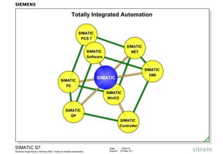
- IntroductionIn the past, the SIMATIC product name was frequently used as a synonym for programmable logic controllers. Today SIMATIC has come to mean much more: SIMATIC is the basic automation system for solving automation tasks in all industries. It consists of standard components in hardware and software, that offer a multitude of possibilities for customer-specific expansions. Two factors have lead to this solution: •the new, comprehensive SIMATIC software, that has the optimal tool for every phase of an automation project and •the members of the SIMATIC automation family, that are more than just programmable logic controllers. TIATotally Integrated Automation is the new way of uniting production and process control technology. All hardware and software components are thus united in a single system with the name SIMATIC. This total integration is made possible by a threefold integraton: •common data management (data are only entered once), •common configuring and programming (modular software), •common communication (simple and uniform configuration).In the slide you can see the individual components of TIA.
- SIMATIC S7The programmable logic controller family consists of the Micro PLC (S7-200) performance range, the lower performance range (S7-300) and the middle/upper performance range (S7-400). SIMATIC C7This complete system is the combination of a PLC (S7-300) and an operator panel of the HMI operator control and process monitoring system. The integration of programmable logic controller and operator panel in one device makes complete machine controls in the smallest space and at an economical price possible. WinACWinAC is a PC-based solution. It is used when various automation tasks (control, visualization, data processing) are to be solved with a PC. There are 2 different products:•WinAC Basic as pure software solution (PLC as Windows NT-Task),•WinAC Pro as hardware solution (PLC as PC card)
- OverviewThe SIMATIC C7 complete system family is a system integration of PLC, I/O and Operator Panel. This concept enables you to implement a complete machine control in the smallest space at an economical price. A PROFIBUS-DP connection was also integrated in the complete device for the C7- 633 DP, C7-634-DP and C7-626 DP complete systems. Complete DevicesThe new SIMATIC C7-620 complete system includes the 6 complete devices - SIMATIC C7-623, C7-633, C7-624, C7-634 and C7-626 - as well as the two space saving C7-621 and C7-621 ASI. All devices are positioned in the lower or lowest performance range of the SIMATIC C7 complete system family. Customer-specifiedFor special requirements that cannot be covered by standard modules, a Expansions customer-specified module can be connected to the SIMATIC C7-620. A customer-specific module can be directly attached to the complete device and a bus connection is established. Programming STEP 7/STEP 7-Mini is used to program and configure the hardware and Configuring configuration of the systems; ProTool/ Lite is used for the HMI configuration. With ProTool/Lite, the SIMATIC C7-623/633 and the SIMATIC C7-624/634 can be selected. All functions that can be configured with OP 5, OP7 and OP 15, OP17, are also supported by SIMATIC C7-620. Special functions were also integrated in the SIMATIC C7-620 to make working with the system easier.
- STEP 7 Microfor configuration, service and commissioning of S7-200 logic controllers STEP 7 Minifor programming, service and commissioning of simple stand-alone applications of S7-300 and C7-620.Unlike STEP 7, there are the following restrictions:•cannot (additionally) load option packages, for example, Engineering Tools.•no communication configuration (CPU - CPU communication) possible. STEP 7Basic package for project planning and programming S7-300/400 logic controllers, with interfaces to the option packages. OptionsOptions are software packages for S7/ M7 for program generation, debugging and commissioning:•S7-SCL= PASCAL-similar high level language.•S7-GRAPH= Graphic programming of sequence control systems. •S7-HiGraph= Graphic programming of machining sequences. •CFC = Graphic configuring and interconnection of blocks. •S7-PLCSIM= Testing the program logic offline on the PG/PC.•S7-Pdiag= Process diagnostics for logic controllers and sequence control systems.•TeleService= Extension of the MPI interface via the telephone network.•HARDPRO = Configuration software for hardware.•DOCPRO= Documentation software. Closed-loop Control Runtime Software (standard function blocks and parameter assigning tools) for (Engineering) solving closed-loop control engineering tasks.
- S7-GRAPHWith the S7-GRAPH programming language, you can clearly and quickly configure and program sequential sequences that you wish to control with an S7 PLC system. The process is thus split into single steps with their own function scope. The sequence is graphically displayed and can be documented with picture and text. The actions to be performed and the transitions, which control the conditions for switching to the next step, are determined in the individual steps. Their definitions, interlocking or monitoring are determined by a subset of the STEP 7 programming language LAD (ladder diagram). S7-GRAPH for S7-300/400 is compatible with the sequence language established in the IEC 1131-3 standard. FunctionalityThe following functions are offered: •Several sequencers in the same S7-GRAPH function block •Free number assignment of the steps and transitions •Simultaneous branches and alternative branches •Jumps (also to other sequence cascades) •Starting/Stopping of sequence cascades as well as activating/holding of steps. Test Functions•Display of active steps or faulty steps •Status display and Modify Variable •Switching between the operating modes: manual, automatic and jogging mode User Interface•Overview, Single Page and Single-step display •Graphic separation of locking controls and monitoring conditions.
- Overview S7-Higraph allows the asychonous processes to be described using state diagrams. The machine or system to be automated is looked upon as a combination of independent elements, the function units. Function UnitsThe function units are the smallest mechanical units of a machine or system. As a rule, a function unit is made up of mechanical and electrical basic elements. In programming, a state diagram is assigned to every function unit. In it, the functional, that is, the mechanical and electrical properties of the function unit are mapped. State DiagramThe state diagram describes the dynamic behaviour of a function unit. It describes the states that a function unit can have, as well as the state transitions. State diagrams can be used more than once. State diagrams that were created once for a specific function unit, can be reused in other progam locations. Diagram Groups By combining parallel running state diagrams, you can describe the complete and Instancesfunctionality of a machine or system. AdvantagesThis &quot;object-oriented&quot; method of S7-HiGraph is well suited for: •the machine and system manufacturer (mechanical engineering) •the automation specialist (electrical engineering) as common means of description •the commissioning engineer and the maintenance specialist The state diagram method helps to optimize the entire process for the creation of a machine or system in the sense of shorter development and turnaround time as well as less commissioning time.
- Overview S7-SCL (Structured Control Language) is a PASCAL-similar high level text language for S7 - 300/400 and C7 and simplifies the programming in control technology for mathematical algorithms, data management and organization tasks. S7-SCL has the PLCopen Base Level certificate and is in accordance with the IEC 1131-3 (Structured Text) standard. With S7-SCL, you can formulate time-saving and economical solutions for automation tasks. FunctionalitySCL offers the functional scope of a high level language such as: •loops •alternatives •branch distributors, etc. combined with control-specific functions such as: •bit accesses to the I/O, bit memories, timers, counters etc. •access to the symbol table •STEP7 block accesses Advantages of SCL •simple to learn programming language especially for beginners •easy to read (understandable) programs are generated. •simpler programming of complex algorithms and processing of complex data structures •integral debugger for symbolic debugging of the source code(single-step, breakpoints, etc.) •system integration in S7 languages such as STL and LAD.
- OverviewWith the engineering tool CFC (Continuous Function Chart), you can create SIMATIC S7 automation tasks by drawing a technology plan - similar to a Function Block Diagram in PLC programming. In this graphic programming method, blocks are positioned in a type of drawing sheet and are graphically interconnected with one another. You can quickly and easily convert technological aspects into complete executable automation programs with CFC. ScopeThe following is supplied with CFC: •CFC Editor •Code Generator •Debugger •Standard block libraries Customer Benefits•The CFC product, as an option package, is smoothly integrated in the STEP 7 architecture with a unified Look&Feel and with common data management. CFC is easy to use, easy to learn and provides consistent data management. •You can use CFC for simple tasks as well as for very complex tasks. •Simple interconnection technology makes communication between blocks user-friendly to configure. •Manual handling and management of machine resources is no longer necessary. •User-friendly testing and debugging are supported
- SFC (Sequential SFC is a sequence control system with step by step execution, that was Function Chart) designed especially for the demands of process control systems (process engineering, process control engineering, etc.). The typical fields of application for sequence control systems of this type are in the areas of discrete production processes. Sequence control systems can, however, also be installed in continuous systems, for example, for startup or shutdown, working point changes as well as state changes due to disturbances etc. With SFC, for example, product manufacturing specifications can be written as event-driven processes. Principle In the SFC Editor, you generate the flow chart by graphic means. The structure Method of Operation elements of the plan are thereby placed according to fixed rules. You do not have to worry about details such as algorithms or the allocation of machine resources, but instead can concentrate on the technological aspects of the configuration. After generating the plan topology, you switch into the detail display (zoom-in configuration) and there assign parameters to the individual elements, that is, you configure the actions (steps) and the conditions (transitions). In the programming of actions, functions of the basis automation, typically generated with CFC, are controlled or selectively processed per operating change and state change. After configuration, you generate the executable machine code through the SFC, download it into the PLC and test it with the SFC test functions.
- Process DiagnosisDiagnosis is important in the operating phase of a plant or machine. Diagnosis is usually initiated when a fault leads to standstill or malfunction of the plant or machine. Programmable logic controllers are widely used in many areas. Field experience has proven that over 98% of faults occur in the peripherals (magnet valves, end switches, etc.). The distribution of fault occurrences makes it meaningful for the diagnosis to focus on process faults, since missing messages or faulty functions lead to down-times and the resulting costs. Process diagnosis diagnoses exactly these external components (sensors, actuators, etc.) or sequences in the process of a plant or machine. S7-PDIAGThe S7-PDIAG software package enables a uniform configuration of the process diagnosis for the SIMATIC S7-300/400 controllers in the LAD, FBD and STL programming languages. You can already define signal monitoring routines including first-up signal acquisition and criteria analysis and input the associated message texts while or after creating the user program in the LAD, FBD or STL programming languages. PDIAG automatically generates monitoring blocks which you must call in your user program. At every call, the fault conditions are checked and in case of an error, the relevant process values are acquired and sent to the display device for the criteria analysis. For the configuration of the operator panel, S7-PDIAG stores the process diagnosis data in a shared database. This data can then be accessed by the OP configuration software SIMATIC ProTool with the option package ProAgent and be made available for display on the operator panel.
- S7 - PLCSIMThe SIMATIC S7-PLCSIM engineering tool (option package) emulates a complete S7-CPU including addresses and I/O on a PG/PC. S7-PLCSIM thus enables you to test a program offline on the PG/PC. All STEP 7 programming languages (STL, LAD, FBD, S7-Graph, S7-HiGraph, S7-SCL and CFC) can be used. S7-PLCSIM allows you to check the functionality of user programs on the PC/PG, regardless of whether the final hardware is available or not. FunctionalityS7-PLCSIM offers the following functions for running a program on a simulated PLC: •An icon in the SIMATIC Manager‘s toolbar switches the Simulation on or off. If the simulation is turned on, every new connection is automatically made to the simulated PLC. If the simulation is turned off, then every new connection is made to the &quot;real&quot; PLC. •You can create view objects that allow you to access memory areas, accu-mulators and tabs of the simulated CPU. You can modify and display all the data in these view objects. •You can change the CPU‘s operating mode (STOP, RUN and RUN-P) just as with a &quot;real&quot; CPU. The simulation also provides a &quot;Pause&quot; function that allows you to halt the program execution without affecting the state of the program. AdvantagesWith S7-PLCSIM, you can detect faults early in the development phase and eliminate them. The quality of the user programs is greatly improved and the commissioning costs are lowered.
- TeleServiceWith Teleservice, SIMATIC S7/C7 PLCs can be remotely maintained with the PG/PC using a telephone network or a radio network. All the while, you have the full functionality of STEP 7 and the Engineering Tools at your disposal. ConfigurationA PG/PC is connected to the PLC using standard modems available on the market. The following are supported: •Analog modems •External ISDN adapter/modems •GSM technology (e.g. D1 network) On the plant side, a teleservice-capable TS adapter is inserted between the standard market modem and the MPI network. All stations (nodes) are thus accessible on the MPI network with this connection. ProcedureTo set up teleservice operation, you must carry out the following steps: •Assigning parameters to the modem on the PG/PC side (TS adapter with default parameters for the modem on the plant side) using the teleservice package. •Establishing a remote connection, supported by an electronic phone book, which includes system management in the form of a file system. •Carrying out remote maintenance with the full function scope of STEP 7 and the Engineering Tools. AdvantagesThrough the accessibility of PLCs in remote (other rooms, plants, etc.) locations you can carry out technical services such as maintenance, update services or fault analysis from a central service base cost effectively.
- DOCPRODOCPRO is a tool for creating and managing plant documentation. DOCPRO allows you to structure project data, prepare wiring manuals and print out all this information in a uniform format. FunctionalityDOCPRO provides you with user-friendly functions for creating and managing the documentation as a wiring manual of the plant: •Creation of wiring manuals and job lists (result of print jobs); a wiring manual is subdivided into job lists. •Central creation, editing and managing of footer data; the individual jobs can also be assigned footers that contain information about the particular job. •Standard layout templates supplied with the program in different formats as the starting point for your own layouts and coversheets. •Automatic and manual assignment of reference numbers; you can assign the job‘s reference numbers according to your own criteria. •Automatic creation of document indexes of the printed documentation. •Printing of job lists and wiring manuals; the jobs of a job list are printed in the predefined sequence. You can take a look at the print reports and status list after printing is completed. AdvantagesThe project data of a project/plant can be clearly documented with DOCPRO. A structured (well-organized) documentation makes additional work on a project as well as service work easier and thus saves time and money.
- Closed-loop In a closed-loop control system process variables are controlled in such a way Control Engineering that they reach their new setpoint values as quickly as possible and that they maintain these in spite of the effect of disturbances. Basic Software The STEP 7 basic package already contains a series of function blocks for PID Controlsolving simple control engineering tasks. Standard This additional package contains blocks and a parameter assignment tool with PID Controlintegrated control setting for standard tasks such as temperature controllers, flow rate regulators, pressure regulators etc. ModularThrough the interconnection of supplied standard function blocks, you can PID Controlimplement just about every closed-loop control engineering structure, even in the upper performance range of process engineering.The package contains 27 FBs and a commissioning tool. Fuzzy ControlFuzzy Systems are used when the mathematic description of a process difficult or even impossible, when a process behaviour is not consistent, when non-linearities occur, but, on the other hand, experience with the process exists. NeuroSystemsNeuronal Systems are used with those problems, whose structure and solution are only partly known.NeuroSystems can be used in all automation levels, from the individual closed-loop controller to the optimization of a plant. Closed-loop Control The closed-loop control modules FM355 (for S7-300) and FM455 (for S7-400) Modules are intelligent 4 and 16 channel modules for universal closed-loop control tasks in chemical and process engineering, with rubber and plastics machinery, with heating and cooling units, in the glass, ceramic and paper industry, etc.
- SIMATIC NETSIMATIC NET is the name of an entire family of networks.•Industrial Ethernet according to IEEE 802.3 - the international standard for the networking of areas and cells •PROFIBUS according to EN 50170 - the international standard for the field area and the cell network with a limited number of nodes •AS-Interface - for communication with sensors and actuators. Industrial EthernetThe Industrial Ethernet network is a cell level network according the international standard IEEE 802.3 (Ethernet) and is designed for industrial use. Extensive open network solutions are possible. A high transmission rate is guaranteed with various transmission media. Industrial Ethernet is an industry standard, world-wide tested and accepted. The Industrial Ethernet network functions according to the IEEE 802.3 standardized accessing procedure CSMA/CD (Carrier sense multiple access with collision detection). ProfibusPROFIBUS is the bus system for cell networks with a limited number of nodes. It is based on the European standard EN 50170, Volume 2, PROFIBUS. Since the requirements according to EN 50170 are fulfilled, PROFIBUS guarantees openness for the connection of components from other manufacturers that conform to standards. The PROFIBUS accessing procedure functions according to the &quot;Token Passing with subordinate Master-Slave&quot; procedure. As a result, a distinction is made between active and passive network participants. AS-InterfaceThe AS-Interface is a networking system for binary sensors and actuators in the field area. With AS-Interface, binary actuators and sensors become capable of communication, for which a direct field bus connection was not technically possible up until now or was not economical.Unlike the powerful PROFIBUS, the main area of use for the AS-Interface line is the transmission of small amounts of information such as from switching positions.
- OverviewFor the SIMATIC S7, there is a field-proven HMI system for user-friendly process control and monitoring available, the SIMATIC HMI. It ranges from the simple text display to the process visualization system. SIMATIC S7 and SIMATIC HMI are completely harmonized and integrated. This simplifies the use of the human-machine interface system SIMATIC HMI considerably. •SIMATIC S7 has already integrated HMI services. The HMI system requests process data from the SIMATIC S7. Data transmission between SIMATIC S7 and SIMATIC HMI is carried out by the two operating systems and does not have to be taken into account in the user program. SIMATIC HMI systems can be connected directly to PPI (S7-200) and MPI or Profibus (S7-300 and S7-400). Operation using PROFIBUS makes process control and monitoring even over greater distances possible. •Numerous features from the uniform database and symbols up to the same user-friendly Windows-oriented user interfaces simplify the use of HMI systems.
- ProToolSIMATIC ProTool and SIMATIC ProTool/Lite are modern configuration tools ProTool/Litefor configuring SIMATIC Text Displays, Operator Panels, Touch Panels as well as the HMI portion of the SIMATIC C7 complete system. While you can configure all devices with SIMATIC ProTool, SIMATIC ProTool/Lite, as the economical version, is restricted to the configuration of line oriented devices. Functionally, SIMATIC ProTool/Lite is a subset of SIMATIC ProTool. The operator control and configuration philosophy of both tools is the same. ProTool/ProSIMATIC ProTool/Pro upwardly expands the existing product family of SIMATIC ProTool with the Operator Panel OP37/Pro and supplements the panels with a runtime software for a standard PC. ProTool/Pro contains the basic functionality of the graphic display units (OP27, OP37) and thus creates a visualization consistency from the existing graphic OPs up to the PC-based systems. ProTool/Pro stands out with the following features: •Runtime software for various platforms -OP37/Pro (Windows 95) -Standard-PC (Windows 95/98 and NT 4.0) •Extensive basic functionality of the graphic OP OP27, OP37 •Expanded functional scope to OP27, OP37
- WinCCSIMATIC WinCC (Windows Control Center) is the open process visualization system from Siemens. It can be integrated problem free in a new or already existing PLC system. Function ModulesThe heart of SIMATIC WinCC is an industry and technology independent basic system with all the important functions for operator control and monitoring, such as: •pixel graphic display •measured value acquisition (archiving functions, data compression, minimum and maximum values etc.) •message display, archiving and reporting •process communication to different PLC systems •standard interfaces, for example, Microsoft programs •documentation of machine and process sequences with individual reports. Basis of WinCCWinCC is based on the 32-bit standard operating systems Windows 95/98 or Windows NT from Mircrosoft. This platform gives WinCC the following functionality: •use of the Windows operating equipment (printer, driver, etc.) •data exchange with other Windows applications via DDE, ODBC, OLE and SQL. •API programming interface •use of hardware available in the market
- IntroductionSIMATIC PCS 7 represents the new control system generation in SIEMENS. It is the consistent, further development and summary of the experiences with TELEPERM M, SIMATIC PCS and SIMATIC S5 based systems. As a result, it is tailored to the process control system tasks in all industries. Engineering The Engineering System can be designed as its own station in the system. It System can however also be loaded as a software package in the OS components at the same time.The Engineering System has the following components: •STEP 7 with the SIMATIC Manager, the central database, and with HW Config for configuring hardware and networks. It also contains the servers, that facilitate consistent configuration between PLC and OS. •SCL (Structured Control Language) as PASCAL-similar higher level programming language for block generation •CFC (Continuous Function Chart) for graphic configuration of the basic automation functions •SFC (Sequential Function Chart) for graphic configuration of production sequences •Expansion of the SIMATIC Manager with a technological hierarchical view •WinCC (Windows Control Center) for OS configuration •DOCPRO for documenting configuration data •Import–/Export wizard for bi-directional data exchange with other CAE systems These components are supplemented by libraries that provide pre-defined blocks for PLC and OS.
- Totally Integrated The new SIMATIC family unifies all devices and systems, that is, hardware as Automationwell as software, into a uniform, powerful system platform. In this platform, the system borders that have existed until now, that is, the borders between computer world, PLC world and process control, that is, between operator control and monitoring and control, between central and distributed automation are overcome. AdvantagesThis totally integrated automation offers you, among other things, the following advantages: •A scalable hardware platform, that is, the optimal (price/performance) functionality (PLC or computer) can be chosen for the task to be solved. •An open totally integrated automation environment, that is, an existing system can be easily extended, or existing or future automation solutions can be integrated. Existing investments retain their value. The transition from an existing SIMATIC, TELEPERM or TI environment can be carried out very easily. •Powerful software increases the productivity in the implementation of a project and thus reduces the engineering and life cycle costs. In addition, expenses for commissioning, maintenance and service are reduced. •SIMATIC is based on Windows standards and can thus easily use their applications (standard software) and communication mechanisms.