SlideShare ist ein Scribd-Unternehmen logo
1 von 5
Downloaden Sie, um offline zu lesen
P. Nagarjuna, k. Devaki Devi / International Journal of Engineering Research and Applications
                         (IJERA) ISSN: 2248-9622 www.ijera.com
                     Vol. 2, Issue5, September- October 2012, pp.535-539
      Design And Optimization Of Sheet Metal Control Arm For
                  Independent Suspension System

                             *P. Nagarjuna, **k. Devaki Devi,
     *
      (Department of Mechanical Engineering, G Pulla Reddy Engineering College, Kurnool, A.P., India,)
     **
       (Department of Mechanical Engineering, G Pulla Reddy Engineering College, Kurnool, A.P., India,)

ABSTRACT:                                                    medium carbon steels, which are sufficiently
          Suspension system of an automobile                 strong as shown in figure.1.
plays an important role in ensuring the stability           This forged component is bulky and heavier
of the automobile. Although it has been achieved             accounting for an increase in vehicle weight.
to a considerable extent, another major aspect of            Moreover, the process of forging the control
suspension system is passenger car is luxury. A              arm is a costlier process as it involves use of
lot of research is going on in this direction, which         complex dies .it also needs a proper care in
led to the development of independent suspension             heating process so as not to effect the strength
system.                                                      of the component.
          Control arm plays a major role in
independent suspension system. It is generally
made of forged steel which has considerable
disadvantages such as weight, cost etc. The
project involves the development of sheet metal
control arm, which has many advantages over
forged metal. The component has been modeled
using the curves extracted from workspace
available in PRO-E. This model is translated into
STEP file, which is than retrieved in
‘Unigraphics’ for analysis.
          The model is subjected to different load
conditions and thus analyzed using Structures
P.E solver. The stress and stiffness of the model is
studied from the results obtained from analysis to
verify the success of the design

I. INTRODUCTION:
I.1 CONTROL ARM:                                         Figure.1: A Suspension System with Ball Joint and
          Control arm is the major part of the           Control
independent suspension system. It forms connection       I.2 FORGING OPERATION:
between the wheel hub and the automobile chassis .                Forging is the operation where the metal is
The main functions of control arm are:                   heated and then a force is applied to manipulate the
 To form a rigid connection between the chassis         metal in such way that the required final shape is
     and wheel hub, to which wheel is attached.          obtained. This is the oldest of the metal working
 It allows the wheel, the required degrees of           processes.
     freedom for proper steering and suspension
     abilities.                                          I.2.1 Forging types:
     It supports the spring and dampers, which form      Smith forging: this is the traditional forging
     the major components for shock absorbing.                operation done openly or in open dies by the
                                                              village black smith or modern shop floor by
 To do these functions properly the control arm
                                                              manual hammering or by power hammers.
     needs to sufficiently strong. Depending upon the
     position of the control arm, there are mainly two        Drop forging: This operation done in closed
     types of control arms                                    impression dies by means of the drop hammer
                                                              .Here the force shaping the component is
                                                              applied in a series of blows.
   Upper and lower control arm. The springs are
    and shock absorbers are supported between                 Press forging: Similar to drop forging, the press
    these arms, which prevents lateral movement of            forging is also done in closed impression dies
    springs. Conventionally the control arms are              with the exception that the forces is continuous
    manufactured by the process of forging the                squeezing type applied by the hydraulic presses.
                                                                   Machine forging: Unlike the drop or press
                                                         forging where the material drawn out, in machine


                                                                                                535 | P a g e
P. Nagarjuna, k. Devaki Devi / International Journal of Engineering Research and Applications
                         (IJERA) ISSN: 2248-9622 www.ijera.com
                     Vol. 2, Issue5, September- October 2012, pp.535-539
forging, the material is upset to get the desired                The design is mainly based on the
shape. The control arms are mostly manufactured by      consideration like decrease of weight and cost etc.
drop forging process.                                   The existing forged component is heavy and its
                                                        manufacturing is complex. So in order to make more
Advantages:                                             reliable it is replaced by sheet metal component
         Uniformity of qualities for parts subjected   which is light and involves more simple operations.
to high stress and loads.                               The workspace for the design is extracted from the
         Close tolerances                              existing forged model. The design and modeling is
         Speed of production                           done using CAD software,”PRO-E”. To obtains the
                                                        workspace the curves are extracted from the extreme
Disadvantages:                                          edges of the workspace model and copied to a new
      High tool cost                                   file. Modeling is done using surfaces. Design with
      High tool maintenance                            surfaces is simpler and complex shapes can be
      No core holes                                    modeled using operations like merging, trim etc.
      Limitations in size and shape                    After the creation of the model using surfaces the
                                                        surface is thicken to 3.5mm using solid protrusion.
I.2.2 Sheet Metal Operation:                                     The rod and washer are designed as per
         The sheet metal operation basically            required dimensions. A standard ball joint of suitable
involves the process of press working consists of       dimension is modeled. The thickness of the sheet
shearing and then plastically working the metal to      metal component is 3.5mm. Practically the ball joint
the desired finished shape and the size through a few   and the rod are attached to the sheet metal
quick strokes under heavy loads .                       component using wields. Sheet metal component can
                                                        be manufactured by making two bends along with
I.2.3 Press Tool Operations:                            form operation and one roll operation. The design is
        Shearing                           shearing,   improvised based on the analysis results and a final
blanking,                                               model is developed.

piercing,trimming,
                                 shaving.
        Tension                          stretch
forming
        Compression                    coining,
sizing,
                                ironing,
hobbing
        Tension and compression       drawing,
spinning,
                                  bending,
forming
                                  and
embossing

Advantages:
       It is one the cheapest and fastest way of
complete manufacture of a component.

Disadvantages:
 Sheet metal operations are generally performed
on the sheets of thickness less than 5mm.

II. DESIGN OF CONTROL ARM
II.1 DESIGN CONSIDERATIONS:                             Figure.2: Existing Forged Model
        Space
        Strength
        Weight
        Manufacturing feasibility
        Cost

II.2 DESIGN PROCEDURE:


                                                                                               536 | P a g e
P. Nagarjuna, k. Devaki Devi / International Journal of Engineering Research and Applications
                         (IJERA) ISSN: 2248-9622 www.ijera.com
                     Vol. 2, Issue5, September- October 2012, pp.535-539
                                                          stiffening, large   deflections   and    large   strain
                                                          capabilities.


Figure.3: Sheet Metal Control Arm
                                                              Figure.6: Tetrahedral Element
II.3 MANUFACTURING PROCESS:
1. A flat blank is created from the design.
2. The blank is then subjected to vertical draw.


  Figure4: Vertical Draw

1. Flange inside operation is performed; it is done in
2 to 3 stage.
2. The sheet is rolled on to the back rod using rolling
punches. It is also performed in      2 to 3 stages.
3. Finally, holes are pierced in the component


                                                                          Figure7: Meshed Component


            Figure5: Flange Inside

III.ANALYSIS
         The final model is exported by “step
translator” to a step file. The created step file is
imported into Unigraphics’ software and converted
to Unigraphics part file. Environment          :
Structures P.E./Linear Statics Plus
  Analysis            : Structural
Linearity             : Linearity:
Time dependency : Steady-state
Solver                 : Structures P.E.
                                                          Figure 8: Rigid Links In Hole
III.1.MESHING:                                                     At the ball joint hole a central node is
          The model is meshed with tetrahedral 10         created and rigid links are created connecting
elements. The element is defined by ten nodes             between the central node and nodes created on the
having three degrees of freedom at each node,             hole during meshing of the component. This is to
translation in the nodal x, y, and z direction. The       make nearest to practicality .The point loads are
element also has plasticity creep, swelling, stress       applied at that central node.


                                                                                                  537 | P a g e
P. Nagarjuna, k. Devaki Devi / International Journal of Engineering Research and Applications
                          (IJERA) ISSN: 2248-9622 www.ijera.com
                      Vol. 2, Issue5, September- October 2012, pp.535-539
Number of elements created = 28276
Number of nodes created    =53272
The analysis is carried for three different load
conditions.

III.2.LOADS AND BOUNDARY CONDITIONS:
The Model has been analyzed for the following load
cases.

III.2.1. Incidental Load case:
These loads act on the vehicle when it is subjected to
high and sudden decelerating forces.

Loads:

Load (N)
            𝑓𝑋                       𝑓𝑌
10910                   4350
 All the loads were applied at the point D.

Boundary Conditions:
z translation fixed for point D.
x, y, z translations fixed for point E1.
                                                          Figure 9: Points Where Loads and Boundary
y, z translations fixed for point E2.
                                                          Conditions To Be Applied
III.2.2Maximum Load case:
These load conditions are observed during regular
operations of the vehicle.                                IV.RESULTS AND DISCUSSIONS
Loads:                                                    IV.1. INCIDENTAL LOAD CASE:
 Load (N)                                                          The maximum stress observed during this
                                                          case is 513 MPa
             𝑓𝑋                        𝑓𝑌                 The yield strength of the material is 540 MPa
 7880                        5860                                  It is observed that, the stress obtained is
                                                          less than the yield strength of material .So the
All the loads were applied at the point D.                control arm withstands the incidental loads.
Boundary Conditions:
z translation fixed for point D.                          IV.2. MAXIMUM LOAD CASE:
x, y, z translation and rotations fixed for point E1.     The maximum stress observed during this case is
x, y, z translation and rotations fixed for point E2.     466 MPaThe yield strength of the material is 540
III.2.3Stiffness calculations:                            MPa
Loads:                                                    It is observed that, the stress obtained is less than the
 Load (N)                                                 yield strength of material .So
                                                          the control arm withstands the maximum loads.
             𝑓𝑋                          𝑓𝑌
  1000                     1000
                                                          IV.3. STIFFNESS LOAD CASE:
All the loads were applied at the point D.                Stiffness calculations:
                                                          Stiffness=force/maximum deflection
Boundary Conditions:                                       𝐾 𝑋 =1000/.1439=5263N/mm
z translation fixed for point D.                           𝐾 𝑌 =1000/.02643=37835N/mm
x,y,z translations fixed for point E1.                     Direction           Objective Stiffness Obtained Stiffness
y,z translations fixed for point E2.                                                 N/mm                N/mm
                                                                    𝐾𝑋          3000                  5263
III.3MATERIAL PROPERTIES:
Modulus of Elasticity =210000 MPa                                   𝐾𝑌          24000                 37835
Poisson’s ratio = 0.3                                     From the stiffness calculations it is observed that,
Steel (safe stress = 540 MPa)                             the control arm satisfies the stiffness requirements in
  It is finally solved using structures P.E solver .The   X and Y-directions.
results obtained are retrieved through post processor
section.


                                                                                                   538 | P a g e
P. Nagarjuna, k. Devaki Devi / International Journal of Engineering Research and Applications
                         (IJERA) ISSN: 2248-9622 www.ijera.com
                     Vol. 2, Issue5, September- October 2012, pp.535-539
                                                        Ease of manufacturing. The sheet metal operations
                                                         are simple and cheap when compared to the forged
                                                         operations.
                                                        Ball joints of different standards can be used by
                                                         varying the size of the hole by changing the
                                                         piercing tool.
                                                        The cost of component is reduced to a
                                                         considerable extent as the raw material used for
                                                         sheet metal component is very cheap than that
                                                         used for forged component.
                                                        The results obtained from analysis infer that the
Figure10: Incident Load Case                             sheet metal component satisfies all the design
                                                         considerations. The stresses obtained for different
                                                         load conditions are within the limits. Stiffness is
                                                         observed to be satisfactory.
                                                          Hence, sheet metal control arm is more beneficial
                                                         than forged control arm.

                                                       REFERENCES
                                                         [1].    R.B.Gupta, “Automobile Engineering”, Satya
                                                                 Prakash publications, 6t edition, 2003
                                                         [2].    Herb Adams, “Chassis Engineering”, Berkley
                                                                 publishing group, Newyork, 1993.
                                                         [3].    www.leafukcar.com
                                                         [4].    Kirpal Singh, “Automobile Engineering”,
Figure11: Maximum Load Condition
                                                                 Standarad publishers, vol 1, 1998.
                                                         [5].    www.tetra.com
                                                         [6].    www.ukcar.com
                                                         [7].    K.K         Jain,         and        R.B.Asthana,
                                                                 “AutomobileEngineering”.Danpathrai
                                                                 publications.
                                                         [8].    Heinz      Heisler,      “Modern       Automobile
                                                                 Engineering”, McGraw Hill publishers, 2001.
                                                         [9].    J.Reimpell,     H.Stoll,     J.W.Betzler,   “The
                                                                 Automotive Chassis”, SAE International, 2nd
                                                                 edition, 2001.
Figure12: Displacement (-X) In Y Direction               [10].   P.N. Rao, “Manufacturing Technology”TATA
                                                                 McGraw Hill publishing company, 7th edition,
                                                                 1987, pp 261-284.
                                                         [11].   Hajra Choudhury, “Work Shop Technology”,
                                                                 Media promoters and publishers, 10th edition,
                                                                 2000, pp 608-620.
                                                         [12].   www.PTC.com
                                                         [13].    www.unigraphics.com
                                                         [14].   www.eds.com


Figure13: Displacement (Z) In X Direction

V.CONCLUSIONS
     From the design and analysis data, it is
  observed that
 The weight of the component is decreased by 25%
  i.e. the weight of the forged model is 4.32 kg and
  the weight of the sheet metal model is 3.23kg.


                                                                                              539 | P a g e

Weitere ähnliche Inhalte

Was ist angesagt?

Project documents on weight optimization of lathe bed
Project documents on weight optimization of lathe bedProject documents on weight optimization of lathe bed
Project documents on weight optimization of lathe bedCollege
 
Sheet metal processes
Sheet metal processesSheet metal processes
Sheet metal processesJagadeesh Km
 
weight optimization of lathe bed using FEA
weight optimization of lathe bed using FEAweight optimization of lathe bed using FEA
weight optimization of lathe bed using FEACollege
 
UCM- Unit 1-introduction to-unconventional_machining_processes
UCM- Unit 1-introduction to-unconventional_machining_processesUCM- Unit 1-introduction to-unconventional_machining_processes
UCM- Unit 1-introduction to-unconventional_machining_processeskarthi keyan
 
ACE305: Aircraft Components Design and Manufacture
ACE305: Aircraft Components Design and ManufactureACE305: Aircraft Components Design and Manufacture
ACE305: Aircraft Components Design and ManufactureDr Mohamed Elfarran
 
Comparison of symmetric and asymmetric steel diagrid structures by non linear...
Comparison of symmetric and asymmetric steel diagrid structures by non linear...Comparison of symmetric and asymmetric steel diagrid structures by non linear...
Comparison of symmetric and asymmetric steel diagrid structures by non linear...eSAT Journals
 
Rod, wire and tube drawing
Rod, wire and tube drawingRod, wire and tube drawing
Rod, wire and tube drawingNaman Dave
 
Study of cutting tools & jig fixture
Study of cutting tools & jig fixtureStudy of cutting tools & jig fixture
Study of cutting tools & jig fixtureAnujKSingh
 
Technological Considerations and Constraints in the Manufacture of High Preci...
Technological Considerations and Constraints in the Manufacture of High Preci...Technological Considerations and Constraints in the Manufacture of High Preci...
Technological Considerations and Constraints in the Manufacture of High Preci...IJERA Editor
 
Sheet metal forming processes
Sheet metal forming processesSheet metal forming processes
Sheet metal forming processesKhushhal Khan
 
IRJET- Behavior of Castellated Beam with Sinusoidal Openings
IRJET- Behavior of Castellated Beam with Sinusoidal OpeningsIRJET- Behavior of Castellated Beam with Sinusoidal Openings
IRJET- Behavior of Castellated Beam with Sinusoidal OpeningsIRJET Journal
 
IRJET- Comparative Analysis on Seismic Behavior of R.C.C, Composite Encased a...
IRJET- Comparative Analysis on Seismic Behavior of R.C.C, Composite Encased a...IRJET- Comparative Analysis on Seismic Behavior of R.C.C, Composite Encased a...
IRJET- Comparative Analysis on Seismic Behavior of R.C.C, Composite Encased a...IRJET Journal
 
IRJET- Estimation of Stress Intensity Factor for the different Crack Mode...
IRJET-  	  Estimation of Stress Intensity Factor for the different Crack Mode...IRJET-  	  Estimation of Stress Intensity Factor for the different Crack Mode...
IRJET- Estimation of Stress Intensity Factor for the different Crack Mode...IRJET Journal
 

Was ist angesagt? (20)

L26067074
L26067074L26067074
L26067074
 
Project documents on weight optimization of lathe bed
Project documents on weight optimization of lathe bedProject documents on weight optimization of lathe bed
Project documents on weight optimization of lathe bed
 
Sheet metal processes
Sheet metal processesSheet metal processes
Sheet metal processes
 
K1302036973
K1302036973K1302036973
K1302036973
 
weight optimization of lathe bed using FEA
weight optimization of lathe bed using FEAweight optimization of lathe bed using FEA
weight optimization of lathe bed using FEA
 
UCM- Unit 1-introduction to-unconventional_machining_processes
UCM- Unit 1-introduction to-unconventional_machining_processesUCM- Unit 1-introduction to-unconventional_machining_processes
UCM- Unit 1-introduction to-unconventional_machining_processes
 
ACE305: Aircraft Components Design and Manufacture
ACE305: Aircraft Components Design and ManufactureACE305: Aircraft Components Design and Manufacture
ACE305: Aircraft Components Design and Manufacture
 
Comparison of symmetric and asymmetric steel diagrid structures by non linear...
Comparison of symmetric and asymmetric steel diagrid structures by non linear...Comparison of symmetric and asymmetric steel diagrid structures by non linear...
Comparison of symmetric and asymmetric steel diagrid structures by non linear...
 
Rod, wire and tube drawing
Rod, wire and tube drawingRod, wire and tube drawing
Rod, wire and tube drawing
 
Study of cutting tools & jig fixture
Study of cutting tools & jig fixtureStudy of cutting tools & jig fixture
Study of cutting tools & jig fixture
 
Forging
ForgingForging
Forging
 
Technological Considerations and Constraints in the Manufacture of High Preci...
Technological Considerations and Constraints in the Manufacture of High Preci...Technological Considerations and Constraints in the Manufacture of High Preci...
Technological Considerations and Constraints in the Manufacture of High Preci...
 
Sheet metal forming processes
Sheet metal forming processesSheet metal forming processes
Sheet metal forming processes
 
Forging ppt
Forging pptForging ppt
Forging ppt
 
IRJET- Behavior of Castellated Beam with Sinusoidal Openings
IRJET- Behavior of Castellated Beam with Sinusoidal OpeningsIRJET- Behavior of Castellated Beam with Sinusoidal Openings
IRJET- Behavior of Castellated Beam with Sinusoidal Openings
 
Forging process
Forging processForging process
Forging process
 
IRJET- Comparative Analysis on Seismic Behavior of R.C.C, Composite Encased a...
IRJET- Comparative Analysis on Seismic Behavior of R.C.C, Composite Encased a...IRJET- Comparative Analysis on Seismic Behavior of R.C.C, Composite Encased a...
IRJET- Comparative Analysis on Seismic Behavior of R.C.C, Composite Encased a...
 
Forging
ForgingForging
Forging
 
IRJET- Estimation of Stress Intensity Factor for the different Crack Mode...
IRJET-  	  Estimation of Stress Intensity Factor for the different Crack Mode...IRJET-  	  Estimation of Stress Intensity Factor for the different Crack Mode...
IRJET- Estimation of Stress Intensity Factor for the different Crack Mode...
 
Met 402 mod_3
Met 402 mod_3Met 402 mod_3
Met 402 mod_3
 

Andere mochten auch (20)

D25014017
D25014017D25014017
D25014017
 
Dp25687691
Dp25687691Dp25687691
Dp25687691
 
Db24664671
Db24664671Db24664671
Db24664671
 
Cq24604607
Cq24604607Cq24604607
Cq24604607
 
Ce25481484
Ce25481484Ce25481484
Ce25481484
 
Cs25561565
Cs25561565Cs25561565
Cs25561565
 
Bq25399403
Bq25399403Bq25399403
Bq25399403
 
Ct24621630
Ct24621630Ct24621630
Ct24621630
 
Dh24703708
Dh24703708Dh24703708
Dh24703708
 
Dk25664666
Dk25664666Dk25664666
Dk25664666
 
Cx24645648
Cx24645648Cx24645648
Cx24645648
 
Bn26425431
Bn26425431Bn26425431
Bn26425431
 
Dp31778783
Dp31778783Dp31778783
Dp31778783
 
Iq2616601665
Iq2616601665Iq2616601665
Iq2616601665
 
Dc31712719
Dc31712719Dc31712719
Dc31712719
 
Caligramas
CaligramasCaligramas
Caligramas
 
Final project 3
Final project 3Final project 3
Final project 3
 
RRMP RDC - Cartes des évaluations de vulnérabilité jan-avril 13
RRMP RDC - Cartes des évaluations de vulnérabilité jan-avril 13RRMP RDC - Cartes des évaluations de vulnérabilité jan-avril 13
RRMP RDC - Cartes des évaluations de vulnérabilité jan-avril 13
 
Alphabet
AlphabetAlphabet
Alphabet
 
Presentacion de la consulta 2011
Presentacion de la consulta 2011Presentacion de la consulta 2011
Presentacion de la consulta 2011
 

Ähnlich wie Co25535539

DESIGN AND ANALYSIS OF MULTIFACE HYDRAULIC BENDING MACHINE DIE
DESIGN AND ANALYSIS OF MULTIFACE HYDRAULIC BENDING MACHINE DIEDESIGN AND ANALYSIS OF MULTIFACE HYDRAULIC BENDING MACHINE DIE
DESIGN AND ANALYSIS OF MULTIFACE HYDRAULIC BENDING MACHINE DIEIRJET Journal
 
Forging Die Design for Gear Blank
Forging Die Design for Gear BlankForging Die Design for Gear Blank
Forging Die Design for Gear BlankIRJET Journal
 
Modelling and Analysis of CNC Milling Machine Bed with Composite Material
Modelling and Analysis of CNC Milling Machine Bed with Composite MaterialModelling and Analysis of CNC Milling Machine Bed with Composite Material
Modelling and Analysis of CNC Milling Machine Bed with Composite Materialijsrd.com
 
Comparative studies on formability analysis in metal
Comparative studies on formability analysis in metalComparative studies on formability analysis in metal
Comparative studies on formability analysis in metaleSAT Publishing House
 
DESIGN AND FABRICATION OF PARALYSIS PATIENT LIFTER
DESIGN AND FABRICATION OF PARALYSIS PATIENT LIFTERDESIGN AND FABRICATION OF PARALYSIS PATIENT LIFTER
DESIGN AND FABRICATION OF PARALYSIS PATIENT LIFTERIRJET Journal
 
IRJET- Fabrication of Roller Bending Machine
IRJET-  	  Fabrication of Roller Bending MachineIRJET-  	  Fabrication of Roller Bending Machine
IRJET- Fabrication of Roller Bending MachineIRJET Journal
 
Study of Manufacturing of Multi-Saddle Clamp
Study of Manufacturing of Multi-Saddle ClampStudy of Manufacturing of Multi-Saddle Clamp
Study of Manufacturing of Multi-Saddle ClampIRJET Journal
 
Dx2645324539
Dx2645324539Dx2645324539
Dx2645324539IJMER
 
Comparative studies on formability analysis in metal forming
Comparative studies on formability analysis in metal formingComparative studies on formability analysis in metal forming
Comparative studies on formability analysis in metal formingeSAT Journals
 
IRJET- CAM Operated Punching Machine
IRJET-  	  CAM Operated Punching MachineIRJET-  	  CAM Operated Punching Machine
IRJET- CAM Operated Punching MachineIRJET Journal
 
Design and fabrication of multiple press tools for sheet metal operation
Design and fabrication of multiple press tools for sheet metal operationDesign and fabrication of multiple press tools for sheet metal operation
Design and fabrication of multiple press tools for sheet metal operationIRJET Journal
 
Finite element analysis of center pin and bracket of jig fixture assembly ijm...
Finite element analysis of center pin and bracket of jig fixture assembly ijm...Finite element analysis of center pin and bracket of jig fixture assembly ijm...
Finite element analysis of center pin and bracket of jig fixture assembly ijm...Dr.Vikas Deulgaonkar
 
IRJET- Design and Fabrication of Manual Roller Bending Machine
IRJET-  	  Design and Fabrication of Manual Roller Bending MachineIRJET-  	  Design and Fabrication of Manual Roller Bending Machine
IRJET- Design and Fabrication of Manual Roller Bending MachineIRJET Journal
 
IRJET- Tool Design for Injection Moulding with Basic Parameters
IRJET- Tool Design for Injection Moulding with Basic ParametersIRJET- Tool Design for Injection Moulding with Basic Parameters
IRJET- Tool Design for Injection Moulding with Basic ParametersIRJET Journal
 
Design and Analysis of Progressive tool in Sheet metal manufacturing
Design and Analysis of Progressive tool in Sheet metal  manufacturingDesign and Analysis of Progressive tool in Sheet metal  manufacturing
Design and Analysis of Progressive tool in Sheet metal manufacturingvivatechijri
 
3 d printing of hollow compounds
3 d printing of hollow compounds3 d printing of hollow compounds
3 d printing of hollow compoundseSAT Journals
 
ABHAY SURY4A M Technical Seminar PPT.ppt
ABHAY SURY4A M Technical Seminar PPT.pptABHAY SURY4A M Technical Seminar PPT.ppt
ABHAY SURY4A M Technical Seminar PPT.pptssuser9b29db
 
Finite Element Analysis and Optimization of Automotive Seat Floor Mounting Br...
Finite Element Analysis and Optimization of Automotive Seat Floor Mounting Br...Finite Element Analysis and Optimization of Automotive Seat Floor Mounting Br...
Finite Element Analysis and Optimization of Automotive Seat Floor Mounting Br...IRJET Journal
 
IRJET- Modeling and Design Analysis of Die Profile of Extrusion of Square...
IRJET-  	  Modeling and Design Analysis of Die Profile of Extrusion of Square...IRJET-  	  Modeling and Design Analysis of Die Profile of Extrusion of Square...
IRJET- Modeling and Design Analysis of Die Profile of Extrusion of Square...IRJET Journal
 

Ähnlich wie Co25535539 (20)

DESIGN AND ANALYSIS OF MULTIFACE HYDRAULIC BENDING MACHINE DIE
DESIGN AND ANALYSIS OF MULTIFACE HYDRAULIC BENDING MACHINE DIEDESIGN AND ANALYSIS OF MULTIFACE HYDRAULIC BENDING MACHINE DIE
DESIGN AND ANALYSIS OF MULTIFACE HYDRAULIC BENDING MACHINE DIE
 
Forging Die Design for Gear Blank
Forging Die Design for Gear BlankForging Die Design for Gear Blank
Forging Die Design for Gear Blank
 
Modelling and Analysis of CNC Milling Machine Bed with Composite Material
Modelling and Analysis of CNC Milling Machine Bed with Composite MaterialModelling and Analysis of CNC Milling Machine Bed with Composite Material
Modelling and Analysis of CNC Milling Machine Bed with Composite Material
 
Comparative studies on formability analysis in metal
Comparative studies on formability analysis in metalComparative studies on formability analysis in metal
Comparative studies on formability analysis in metal
 
DESIGN AND FABRICATION OF PARALYSIS PATIENT LIFTER
DESIGN AND FABRICATION OF PARALYSIS PATIENT LIFTERDESIGN AND FABRICATION OF PARALYSIS PATIENT LIFTER
DESIGN AND FABRICATION OF PARALYSIS PATIENT LIFTER
 
IRJET- Fabrication of Roller Bending Machine
IRJET-  	  Fabrication of Roller Bending MachineIRJET-  	  Fabrication of Roller Bending Machine
IRJET- Fabrication of Roller Bending Machine
 
H012214651
H012214651H012214651
H012214651
 
Study of Manufacturing of Multi-Saddle Clamp
Study of Manufacturing of Multi-Saddle ClampStudy of Manufacturing of Multi-Saddle Clamp
Study of Manufacturing of Multi-Saddle Clamp
 
Dx2645324539
Dx2645324539Dx2645324539
Dx2645324539
 
Comparative studies on formability analysis in metal forming
Comparative studies on formability analysis in metal formingComparative studies on formability analysis in metal forming
Comparative studies on formability analysis in metal forming
 
IRJET- CAM Operated Punching Machine
IRJET-  	  CAM Operated Punching MachineIRJET-  	  CAM Operated Punching Machine
IRJET- CAM Operated Punching Machine
 
Design and fabrication of multiple press tools for sheet metal operation
Design and fabrication of multiple press tools for sheet metal operationDesign and fabrication of multiple press tools for sheet metal operation
Design and fabrication of multiple press tools for sheet metal operation
 
Finite element analysis of center pin and bracket of jig fixture assembly ijm...
Finite element analysis of center pin and bracket of jig fixture assembly ijm...Finite element analysis of center pin and bracket of jig fixture assembly ijm...
Finite element analysis of center pin and bracket of jig fixture assembly ijm...
 
IRJET- Design and Fabrication of Manual Roller Bending Machine
IRJET-  	  Design and Fabrication of Manual Roller Bending MachineIRJET-  	  Design and Fabrication of Manual Roller Bending Machine
IRJET- Design and Fabrication of Manual Roller Bending Machine
 
IRJET- Tool Design for Injection Moulding with Basic Parameters
IRJET- Tool Design for Injection Moulding with Basic ParametersIRJET- Tool Design for Injection Moulding with Basic Parameters
IRJET- Tool Design for Injection Moulding with Basic Parameters
 
Design and Analysis of Progressive tool in Sheet metal manufacturing
Design and Analysis of Progressive tool in Sheet metal  manufacturingDesign and Analysis of Progressive tool in Sheet metal  manufacturing
Design and Analysis of Progressive tool in Sheet metal manufacturing
 
3 d printing of hollow compounds
3 d printing of hollow compounds3 d printing of hollow compounds
3 d printing of hollow compounds
 
ABHAY SURY4A M Technical Seminar PPT.ppt
ABHAY SURY4A M Technical Seminar PPT.pptABHAY SURY4A M Technical Seminar PPT.ppt
ABHAY SURY4A M Technical Seminar PPT.ppt
 
Finite Element Analysis and Optimization of Automotive Seat Floor Mounting Br...
Finite Element Analysis and Optimization of Automotive Seat Floor Mounting Br...Finite Element Analysis and Optimization of Automotive Seat Floor Mounting Br...
Finite Element Analysis and Optimization of Automotive Seat Floor Mounting Br...
 
IRJET- Modeling and Design Analysis of Die Profile of Extrusion of Square...
IRJET-  	  Modeling and Design Analysis of Die Profile of Extrusion of Square...IRJET-  	  Modeling and Design Analysis of Die Profile of Extrusion of Square...
IRJET- Modeling and Design Analysis of Die Profile of Extrusion of Square...
 

Co25535539

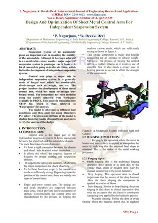
  • 1. P. Nagarjuna, k. Devaki Devi / International Journal of Engineering Research and Applications (IJERA) ISSN: 2248-9622 www.ijera.com Vol. 2, Issue5, September- October 2012, pp.535-539 Design And Optimization Of Sheet Metal Control Arm For Independent Suspension System *P. Nagarjuna, **k. Devaki Devi, * (Department of Mechanical Engineering, G Pulla Reddy Engineering College, Kurnool, A.P., India,) ** (Department of Mechanical Engineering, G Pulla Reddy Engineering College, Kurnool, A.P., India,) ABSTRACT: medium carbon steels, which are sufficiently Suspension system of an automobile strong as shown in figure.1. plays an important role in ensuring the stability  This forged component is bulky and heavier of the automobile. Although it has been achieved accounting for an increase in vehicle weight. to a considerable extent, another major aspect of Moreover, the process of forging the control suspension system is passenger car is luxury. A arm is a costlier process as it involves use of lot of research is going on in this direction, which complex dies .it also needs a proper care in led to the development of independent suspension heating process so as not to effect the strength system. of the component. Control arm plays a major role in independent suspension system. It is generally made of forged steel which has considerable disadvantages such as weight, cost etc. The project involves the development of sheet metal control arm, which has many advantages over forged metal. The component has been modeled using the curves extracted from workspace available in PRO-E. This model is translated into STEP file, which is than retrieved in ‘Unigraphics’ for analysis. The model is subjected to different load conditions and thus analyzed using Structures P.E solver. The stress and stiffness of the model is studied from the results obtained from analysis to verify the success of the design I. INTRODUCTION: I.1 CONTROL ARM: Figure.1: A Suspension System with Ball Joint and Control arm is the major part of the Control independent suspension system. It forms connection I.2 FORGING OPERATION: between the wheel hub and the automobile chassis . Forging is the operation where the metal is The main functions of control arm are: heated and then a force is applied to manipulate the  To form a rigid connection between the chassis metal in such way that the required final shape is and wheel hub, to which wheel is attached. obtained. This is the oldest of the metal working  It allows the wheel, the required degrees of processes. freedom for proper steering and suspension abilities. I.2.1 Forging types:  It supports the spring and dampers, which form  Smith forging: this is the traditional forging the major components for shock absorbing. operation done openly or in open dies by the village black smith or modern shop floor by  To do these functions properly the control arm manual hammering or by power hammers. needs to sufficiently strong. Depending upon the position of the control arm, there are mainly two  Drop forging: This operation done in closed types of control arms impression dies by means of the drop hammer .Here the force shaping the component is applied in a series of blows.  Upper and lower control arm. The springs are and shock absorbers are supported between  Press forging: Similar to drop forging, the press these arms, which prevents lateral movement of forging is also done in closed impression dies springs. Conventionally the control arms are with the exception that the forces is continuous manufactured by the process of forging the squeezing type applied by the hydraulic presses. Machine forging: Unlike the drop or press forging where the material drawn out, in machine 535 | P a g e
  • 2. P. Nagarjuna, k. Devaki Devi / International Journal of Engineering Research and Applications (IJERA) ISSN: 2248-9622 www.ijera.com Vol. 2, Issue5, September- October 2012, pp.535-539 forging, the material is upset to get the desired The design is mainly based on the shape. The control arms are mostly manufactured by consideration like decrease of weight and cost etc. drop forging process. The existing forged component is heavy and its manufacturing is complex. So in order to make more Advantages: reliable it is replaced by sheet metal component  Uniformity of qualities for parts subjected which is light and involves more simple operations. to high stress and loads. The workspace for the design is extracted from the  Close tolerances existing forged model. The design and modeling is  Speed of production done using CAD software,”PRO-E”. To obtains the workspace the curves are extracted from the extreme Disadvantages: edges of the workspace model and copied to a new  High tool cost file. Modeling is done using surfaces. Design with  High tool maintenance surfaces is simpler and complex shapes can be  No core holes modeled using operations like merging, trim etc.  Limitations in size and shape After the creation of the model using surfaces the surface is thicken to 3.5mm using solid protrusion. I.2.2 Sheet Metal Operation: The rod and washer are designed as per The sheet metal operation basically required dimensions. A standard ball joint of suitable involves the process of press working consists of dimension is modeled. The thickness of the sheet shearing and then plastically working the metal to metal component is 3.5mm. Practically the ball joint the desired finished shape and the size through a few and the rod are attached to the sheet metal quick strokes under heavy loads . component using wields. Sheet metal component can be manufactured by making two bends along with I.2.3 Press Tool Operations: form operation and one roll operation. The design is  Shearing shearing, improvised based on the analysis results and a final blanking, model is developed. piercing,trimming, shaving.  Tension stretch forming  Compression coining, sizing,  ironing, hobbing  Tension and compression drawing, spinning, bending, forming and embossing Advantages:  It is one the cheapest and fastest way of complete manufacture of a component. Disadvantages:  Sheet metal operations are generally performed on the sheets of thickness less than 5mm. II. DESIGN OF CONTROL ARM II.1 DESIGN CONSIDERATIONS: Figure.2: Existing Forged Model  Space  Strength  Weight  Manufacturing feasibility  Cost II.2 DESIGN PROCEDURE: 536 | P a g e
  • 3. P. Nagarjuna, k. Devaki Devi / International Journal of Engineering Research and Applications (IJERA) ISSN: 2248-9622 www.ijera.com Vol. 2, Issue5, September- October 2012, pp.535-539 stiffening, large deflections and large strain capabilities. Figure.3: Sheet Metal Control Arm Figure.6: Tetrahedral Element II.3 MANUFACTURING PROCESS: 1. A flat blank is created from the design. 2. The blank is then subjected to vertical draw. Figure4: Vertical Draw 1. Flange inside operation is performed; it is done in 2 to 3 stage. 2. The sheet is rolled on to the back rod using rolling punches. It is also performed in 2 to 3 stages. 3. Finally, holes are pierced in the component Figure7: Meshed Component Figure5: Flange Inside III.ANALYSIS The final model is exported by “step translator” to a step file. The created step file is imported into Unigraphics’ software and converted to Unigraphics part file. Environment : Structures P.E./Linear Statics Plus Analysis : Structural Linearity : Linearity: Time dependency : Steady-state Solver : Structures P.E. Figure 8: Rigid Links In Hole III.1.MESHING: At the ball joint hole a central node is The model is meshed with tetrahedral 10 created and rigid links are created connecting elements. The element is defined by ten nodes between the central node and nodes created on the having three degrees of freedom at each node, hole during meshing of the component. This is to translation in the nodal x, y, and z direction. The make nearest to practicality .The point loads are element also has plasticity creep, swelling, stress applied at that central node. 537 | P a g e
  • 4. P. Nagarjuna, k. Devaki Devi / International Journal of Engineering Research and Applications (IJERA) ISSN: 2248-9622 www.ijera.com Vol. 2, Issue5, September- October 2012, pp.535-539 Number of elements created = 28276 Number of nodes created =53272 The analysis is carried for three different load conditions. III.2.LOADS AND BOUNDARY CONDITIONS: The Model has been analyzed for the following load cases. III.2.1. Incidental Load case: These loads act on the vehicle when it is subjected to high and sudden decelerating forces. Loads: Load (N) 𝑓𝑋 𝑓𝑌 10910 4350 All the loads were applied at the point D. Boundary Conditions: z translation fixed for point D. x, y, z translations fixed for point E1. Figure 9: Points Where Loads and Boundary y, z translations fixed for point E2. Conditions To Be Applied III.2.2Maximum Load case: These load conditions are observed during regular operations of the vehicle. IV.RESULTS AND DISCUSSIONS Loads: IV.1. INCIDENTAL LOAD CASE: Load (N) The maximum stress observed during this case is 513 MPa 𝑓𝑋 𝑓𝑌 The yield strength of the material is 540 MPa 7880 5860 It is observed that, the stress obtained is less than the yield strength of material .So the All the loads were applied at the point D. control arm withstands the incidental loads. Boundary Conditions: z translation fixed for point D. IV.2. MAXIMUM LOAD CASE: x, y, z translation and rotations fixed for point E1. The maximum stress observed during this case is x, y, z translation and rotations fixed for point E2. 466 MPaThe yield strength of the material is 540 III.2.3Stiffness calculations: MPa Loads: It is observed that, the stress obtained is less than the Load (N) yield strength of material .So the control arm withstands the maximum loads. 𝑓𝑋 𝑓𝑌 1000 1000 IV.3. STIFFNESS LOAD CASE: All the loads were applied at the point D. Stiffness calculations: Stiffness=force/maximum deflection Boundary Conditions: 𝐾 𝑋 =1000/.1439=5263N/mm z translation fixed for point D. 𝐾 𝑌 =1000/.02643=37835N/mm x,y,z translations fixed for point E1. Direction Objective Stiffness Obtained Stiffness y,z translations fixed for point E2. N/mm N/mm 𝐾𝑋 3000 5263 III.3MATERIAL PROPERTIES: Modulus of Elasticity =210000 MPa 𝐾𝑌 24000 37835 Poisson’s ratio = 0.3 From the stiffness calculations it is observed that, Steel (safe stress = 540 MPa) the control arm satisfies the stiffness requirements in It is finally solved using structures P.E solver .The X and Y-directions. results obtained are retrieved through post processor section. 538 | P a g e
  • 5. P. Nagarjuna, k. Devaki Devi / International Journal of Engineering Research and Applications (IJERA) ISSN: 2248-9622 www.ijera.com Vol. 2, Issue5, September- October 2012, pp.535-539  Ease of manufacturing. The sheet metal operations are simple and cheap when compared to the forged operations.  Ball joints of different standards can be used by varying the size of the hole by changing the piercing tool.  The cost of component is reduced to a considerable extent as the raw material used for sheet metal component is very cheap than that used for forged component.  The results obtained from analysis infer that the Figure10: Incident Load Case sheet metal component satisfies all the design considerations. The stresses obtained for different load conditions are within the limits. Stiffness is observed to be satisfactory. Hence, sheet metal control arm is more beneficial than forged control arm. REFERENCES [1]. R.B.Gupta, “Automobile Engineering”, Satya Prakash publications, 6t edition, 2003 [2]. Herb Adams, “Chassis Engineering”, Berkley publishing group, Newyork, 1993. [3]. www.leafukcar.com [4]. Kirpal Singh, “Automobile Engineering”, Figure11: Maximum Load Condition Standarad publishers, vol 1, 1998. [5]. www.tetra.com [6]. www.ukcar.com [7]. K.K Jain, and R.B.Asthana, “AutomobileEngineering”.Danpathrai publications. [8]. Heinz Heisler, “Modern Automobile Engineering”, McGraw Hill publishers, 2001. [9]. J.Reimpell, H.Stoll, J.W.Betzler, “The Automotive Chassis”, SAE International, 2nd edition, 2001. Figure12: Displacement (-X) In Y Direction [10]. P.N. Rao, “Manufacturing Technology”TATA McGraw Hill publishing company, 7th edition, 1987, pp 261-284. [11]. Hajra Choudhury, “Work Shop Technology”, Media promoters and publishers, 10th edition, 2000, pp 608-620. [12]. www.PTC.com [13]. www.unigraphics.com [14]. www.eds.com Figure13: Displacement (Z) In X Direction V.CONCLUSIONS From the design and analysis data, it is observed that  The weight of the component is decreased by 25% i.e. the weight of the forged model is 4.32 kg and the weight of the sheet metal model is 3.23kg. 539 | P a g e