Disha NEET Physics Guide for classes 11 and 12.pdf
4 beams
1. Design of Steel Structures Prof. S.R.Satish Kumar and Prof. A.R.Santha Kumar
5.4 Beams
As stated previously, the effect of local buckling should invariably be taken
into account in thin walled members, using methods described already. Laterally
stable beams are beams, which do not buckle laterally. Designs may be carried
out using simple beam theory, making suitable modifications to take account of
local buckling of the webs. This is done by imposing a maximum compressive
stress, which may be considered to act on the bending element. The maximum
value of the stress is given by
⎡ D fy ⎤
p 0 = ⎢1.13 − 0.0019 ⎥ py ≥ fy
/ (5.11)
⎢
⎣
t 280 ⎥
⎦
Where po = the limiting value of compressive stress in N/mm2
D/t = web depth/thickness ratio
fy = material yield stress in N/mm2.
py = design strength in N/mm2
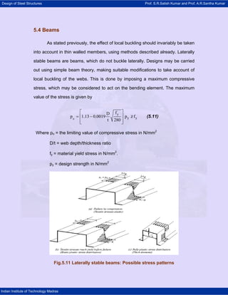
Fig.5.11 Laterally stable beams: Possible stress patterns
Indian Institute of Technology Madras
2. Design of Steel Structures Prof. S.R.Satish Kumar and Prof. A.R.Santha Kumar
For steel with fy = 280 N/mm2, p0 = fy when (D/t) ? 68.
For greater web slenderness values, local web buckling has a detrimental
effect. The moment capacity of the cross section is determined by limiting the
maximum stress on the web to p0. The effective width of the compression
element is evaluated using this stress and the effective section properties are
evaluated. The ultimate moment capacity (Mult) is given by
Mult = Zc.p0 (5.11a)
Where Zc = effective compression section modulus
This is subject to the condition that the maximum tensile stress in the
section does not exceed fy (see Fig.5.11a).
If the neutral axis is such that the tensile stresses reach yield first, then the
moment capacity is to be evaluated on the basis of elasto-plastic stress
distribution (see Fig.5.11b). In elements having low (width/thickness) ratios,
compressive stress at collapse can equal yield stress (see Fig. 5.11c). In order to
ensure yielding before local buckling, the maximum (width/thickness) ratio of
280 280
stiffened elements is ≤ 25 and for unstiffened elements, it is ≤ 8
fy fy
5.4.1 Other beam failure criteria
5.4.1.1 Web crushing
This may occur under concentrated loads or at support point when deep
slender webs are employed. A widely used method of overcoming web crushing
problems is to use web cleats at support points (See Fig.5.12).
Indian Institute of Technology Madras
3. Design of Steel Structures Prof. S.R.Satish Kumar and Prof. A.R.Santha Kumar
Fig.5.12 Web crushing and how to avoid it
5.4.1.2 Shear buckling
Fig. 5.13 Web buckling
The phenomenon of shear buckling of thin webs has been discussed in
detail in the chapter on "Plate Girders". Thin webs subjected to predominant
shear will buckle as shown in Fig.5.13. The maximum shear in a beam web is
invariably limited to 0.7 times yield stress in shear. In addition in deep webs,
where shear buckling can occur, the average shear stress (pv) must be less than
the value calculated as follows:
2
⎛ 1000 t ⎞
pv ≤ ⎜ ⎟ (5.12)
⎝ D ⎠
Where p = average shear stress in N/mm2.
t and D are the web thickness and depth respectively ( in mm )
Indian Institute of Technology Madras
4. Design of Steel Structures Prof. S.R.Satish Kumar and Prof. A.R.Santha Kumar
5.4.2 Lateral buckling
The great majority of cold formed beams are (by design) restrained
against lateral deflections. This is achieved by connecting them to adjacent
elements, roof sheeting or to bracing members. However, there are
circumstances where this is not the case and the possibility of lateral buckling
has to be considered.
Lateral buckling will not occur if the beam under loading bends only about
the minor axis. If the beam is provided with lateral restraints, capable of resisting
a lateral force of 3% of the maximum force in the compression flange, the beam
may be regarded as restrained and no lateral buckling will occur.
As described in the chapter on "Unrestrained Beams'", lateral buckling
occurs only in "long" beams and is characterised by the beam moving laterally
and twisting when a transverse load is applied. This type of buckling is of
importance for long beams with low lateral stiffness and low torsional stiffness
(See Fig.5.14); such beams under loading will bend about the major axis.
The design approach is based on the "effective length" of the beam for
lateral buckling, which is dependent on support and loading conditions. The
effective length of beams with both ends supported and having restraints against
twisting is taken as 0.9 times the length, provided the load is applied at bottom
flange level. If a load is applied to the top flange which is unrestrained laterally,
the effective length is increased by 20%. This is considered to be a "destabilising
load", i.e. a load that encourages lateral instability.
Indian Institute of Technology Madras
5. Design of Steel Structures Prof. S.R.Satish Kumar and Prof. A.R.Santha Kumar
The elastic lateral buckling moment capacity is determined next. For an I
section or symmetrical channel section bent in the plane of the web and loaded
through shear centre, this is
2
π2 A.E.D 1 ⎛l t ⎞
ME = .Cb 1+ ⎜ e . ⎟ (5.13)
20 ⎜ ry D ⎟
( )
2
2 le / ry ⎝ ⎠
Where,
A = cross sectional area, in mm2
D = web depth, in mm
t = web thickness, in mm
ry = radius of gyration for the lateral bending of section
Cb = 1.75 - 1.05 β + 0.3 β2 x 2.3.
Fig.5.14 Lateral buckling
Indian Institute of Technology Madras
6. Design of Steel Structures Prof. S.R.Satish Kumar and Prof. A.R.Santha Kumar
Where β = ratio of the smaller end moment to the larger end moment M in
an unbraced length of beam. β is taken positive for single curvature bending and
negative for double curvature (see Fig. 5.15)
To provide for the effects of imperfections, the bending capacity in the
plane of loading and other effects, the value of ME obtained from eq. (5.13) will
need to be modified. The basic concept used is explained in the chapter on
Column Buckling where the failure load of a column is obtained by employing the
Perry-Robertson equation for evaluating the collapse load of a column from a
knowledge of the yield load and Euler buckling load.
ME = Elastic lateral buckling resistance moment given by equation (5.13)
Fig. 5.15 Single and double curvature bending
A similar Perry-Robertson type equation is employed for evaluating the
Moment Resistance of the beam
Indian Institute of Technology Madras
7. Design of Steel Structures Prof. S.R.Satish Kumar and Prof. A.R.Santha Kumar
1⎡ ⎤
{ }
⎢ M y + (1 + η ) M E − ⎣ M y + (1 + η ) M E ⎦ − 4M y .M E ⎥
2
Mb = ⎡ ⎤ (5.14)
2⎣ ⎦
My = First yield moment given by the product of yield stress (fy) and the
Elastic Modulus (Zc) of the gross section.
η = Perry coefficient, given by
le
When < 40Cb , η= 0.
ry
le ⎛l ⎞
When < 40Cb , η= 0.002 ⎜ e − 40Cb ⎟
ry ⎜ ry ⎟
⎝ ⎠
le = effective length
ry = radius of gyration of the section about the y - axis.
When the calculated value of Mb exceed Mult calculated by using equation
(5.11.a), then Mb is limited to Mult. This will happen when the beams are "short".
Indian Institute of Technology Madras