SlideShare ist ein Scribd-Unternehmen logo
1 von 8
Downloaden Sie, um offline zu lesen
SURVEYING INSTRUMENTS


                      Series30R
                              Reflectorless Total Stations


        350m • 1,140ft. Reflectorless Range*
Cutting-Edge Technologies Packed in a Compact Body
                                                    * Class 3R models


                                                Laser beam image is simulated.
Series30R

                               Innovative Technology Makes Reflectorless
                               EDM More Powerful Than Ever

  ■ New advances with RED-tech EDM
  Sokkia’s revolutionary digital signal processing technology, RED-tech, relies on a unique procedure for measurement beam analysis. Using an
  A/D converter, it simultaneously samples measuring signals in three different frequencies. Furthermore, RED-tech uses advanced software to
  calculate distances. As a result, RED-tech ensures that the calculation method most suited to the condition of the measuring beam is selected. It
  also is able to deliver greater accuracy, speed, and range.

                                                                                                                                              And now, RED-tech has been further
                                                                                                                                              enhanced through the inclusion of improved
                                                                                                                                              optical and electronic components. Its new
                                                                                                                                              light emitting and receiving optics provide the
                                                                                                                                              ideal light path for capturing light with
                                                                                                                                              minimal loss. And its new highly tunable
                                                                                                                                              optical filter, which captures multiple samples
                                                                                                                                              of beams carrying the correct measurement
                                                                                                                                              information, gives you greater precision with
                                                                                                                                              difficult-to-measure objects. Thanks to these
                                                                                                                                              new components and its advanced
                                                                                                                                              technology, RED-tech EDM paves the way to
                                                                                                                                              unprecedented distance measurement
                                                                                                                                              possibilities.


                                                                                                                                                                             Sampling image


  ■ Ultra-wide reflectorless measurement range
  From extra-long distances to remarkably short ones, the Series30R offers accurate reflectorless measurement over a tremendous range of
  distances. The Series30R total stations feature a Class 3R laser, and cover a range from 0.3m to 350m (1ft. to 1,140ft.). Models equipped with a
  Class 2 laser are also available. These have a reach of up to 150m (490ft.) or 100m (320ft.).
  Distances based on use of the white side of a KODAK Gray Card.


  ■ Reflectorless measurement                                                                                                          ■ Sokkia’s traditional optics
    range and accuracy with a Kodak Gray Card                                                                                          Sokkia’s traditional optics have never been more
                                                                                                                                       refined. Light is projected from the middle of an
   SET230R3 • SET330R3 • SET530R3                                                                                                      objective lens and received along its periphery.
   Class 3R laser products
                                                                                                                                       When combined with a narrow measuring beam, this
    White side
                                                         ±(3 + 2ppm x D)mm                                                             design enables pinpoint measurement and is highly
    90% reflective
                                                                                                                                       effective even with narrow objects. Furthermore, the
    Gray side                                                                                     200m (650ft.)     350m (1,140ft.)
                                   ±(3 + 2ppm x D)mm                                                                                   new telescope provides an extremely bright and
    18% reflective                                                                                                ±(5 + 10ppm x D)mm
                                                                                                                                       sharp sight.
                 0.3m (1ft.)                                   100m (320ft.)               170m (550ft.)
                                                                                 ±(5 + 5ppm x D)mm
   SET230R • SET330R • SET530R
   Class 2 laser products
    White side                      ±(3 + 2ppm x D)mm
    90% reflective                                                                       ±(5 + 10ppm x D)mm
                                                                 100m (320ft.)    150m (490ft.)
    Gray side
    18% reflective
                                                                   ±(5 + 5ppm x D)mm
                 0.3m (1ft.)              45m (140ft.) 80m (260ft.)
                                            ±(3 + 2ppm x D)mm                                                                                                                       Receiver
   SET630R
   Class 2 laser product
    White side                      ±(3 + 2ppm x D)mm
    90% reflective
                                                                                                                                                           Transmitter
                                                               100m (320ft.)                                                             Optics diagram
    Gray side
    18% reflective
                                                        ±(5 + 5ppm x D)mm
                     0.3m (1ft.)    30m (98ft.) 50m (160ft.)
                                          ±(3 + 2ppm x D)mm
■ Ultra-narrow visible laser for pinpoint accuracy

                                                                                        A
                                                             A                          Series30R: The ultra-narrow laser beam enables
                                                                                        accurate measurements through obstacles such as
                                                                                        chain-link fences, tree branches, etc.
                                                                                        Broader beam models: Both the fence and wall get measured, which
                                                                                        leads to erroneous measurement.
         B
                                                                                                                                   C
                                                                                                                                   Series30R:
                                                                                                                                   Measurements at
                                                                                                                                   small incident
                                                                                                                                   angles, such as with
                                                                      A                                                            manholes on the
                                                                                                             C                     road surface, are
                                                                                                                                   handled with high
                                                B
  B                                                                                                                                precision by the
  Series30R:                                                                                                                       ultra-narrow laser
  The measuring beam is                                                                                                            measuring beam.
  extremely narrow, so                                                                                                             Broader beam models:
  distances to walls and                                                                                                           Wider measuring beams end
  corners can be measured                                                                                                          up covering a larger area
  with pinpoint accuracy.                                                                                                          than expected at small
                                                                                                                                   incident angles, resulting in
  Broader beam models: A wide
                                                                                                                                   measurements that are too
  measuring beam hits points near                                                        C                                         long or short.
  and far at the same time, resulting
  in inaccurate measurement.


The Series30R employs an ultra small-diameter visible laser to obtain measurements with pinpoint
accuracy. Fine objects, as well as the corners of walls and other structures, can be measured precisely.
You can also make accurate measurements through obstacles such as chain-link fences and tree
branches.


■ Laser-pointer function
The visible laser beam can be used as a convenient laser pointer for interior leveling work, vertical
alignment, setting out, and other tasks.


■ Long-distance measurement with reflectors
Measure long distances by directing the laser beam at a reflector. When using a single
AP prism, you can measure as far as 5,000m (16,400ft.)* at once, with an accuracy of
±(2 + 2ppm x D)mm. In addition, reflective sheet targets may be used to get
measurements of up to 500m (1,640ft.)** with ±(3 + 2ppm x D)mm precision. Choose
from Sokkia’s wide selection of sheet targets to suit your needs. Rotating pin-pole
targets, two-point target for measuring hidden points, and many other innovative
reflective targets are available.
* In good weather conditions except SET630R. ** When using RS90N-K.

                          In the reflective sheet or prism modes, maximum laser output is
                          automatically reduced to 0.22mW. This is equivalent to the level of
                          a Class 1 laser. The Series30R also includes a safety filter in the
                          telescope, which protects your eye from the laser beam if you
                          happen to sight a reflective prism or sheet target while in
                          reflectorless mode.
Series30R

                   A Durable Partner That Gives Heavy-Duty
                   Support for Daily Surveying Needs


  ■ Sokkia's original absolute encoder                                           ■ Status check at a glance
                                                                                 The built-in control panel has an easy-to-view LCD screen with 192 x
                                                                                 80 pixel resolution. Key information, such as EDM mode
                                                                                 (reflectorless, prism, or reflective sheet target) and laser beam
                                                                                 status, can be checked at a glance.
                                  LED

                                                        CCD


          Absolute encoder disk


   Encoder diagram

  The Series30R models are equipped with Sokkia-developed absolute
  encoders. These encoders feature the RAB (RAndom Bi-directional)
  code technology first used in the SDL30 digital level, which provides
  high stability and reliability. You do not need to reset for 0 indexing at
  the start of a job, so surveying can begin from the moment you turn
  on the power. Work efficiency is also boosted by the immediate                                             Reflectorless mode
  display of azimuth whenever you restart the total station.


  ■ Triple-axis compensation for high
    reliability
  Vertical and horizontal angles are compensated for by a dual-axis                     Reflective sheet                           Prism mode
  compensator that detects the tilt of the total station in two directions.             target mode
  In addition, a collimation function corrects the deviation of the
  telescope's mechanical axis. Working together, these features offer
  maximum reliability with angle measurements.

                                                                                 ■ One-touch target selection
  ■ Password function for security                                               There are no complicated operations when it comes to selecting
  The Series30R includes a password-protection function for security             targets. The Series30R total stations let you switch between
  purposes. You can assign your own password to the instrument to                reflectorless, prism, and reflective sheet target just by pressing the
  prevent unauthorized use.                                                      SFT key in sequence. The selected target is displayed on the
                                                                                 operation panel for easy confirmation.


  ■ Large internal memory                                                        ■ User-friendly keyboard and softkeys
  The Series30R can store approximately 10,000 data points, including            The control panel also includes large, ergonomic buttons as well as
  known points and other information. To facilitate concurrent use at            four softkeys (F1-F4). Softkey functions are structured into 3 pages
  different work sites, data may be sorted into 10 different job files.          and 12 modes, and you are free to assign functions to any key you
                                                                                 like. Productivity is enhanced through this balance of functionality
                                                                                 and ease of use.
  ■ CompactFlash card unit
    (Factory option*)                                                            ■ Exceptional durability
                                  A card unit for commercially available
                                  CompactFlash memory cards can be               Featuring advanced protection against water and dust, the
                                  added as a factory option. 72,000 points       Series30R total stations are ideal for use in inclement weather,
                                  (eighteen 4,000-point files) can be stored     humid environments, or at dusty work sites. (IP66 compliant)
                                  with an 8MB memory card, while a 16MB
                                  memory card provides 144,000 points of
                                  data storage (thirty-six 4,000-point files).
                                  * Not available for SET630R
■ SF14 wireless keyboard (Option*)                                                                       ■ Guide Light Unit GDL1 (Factory option)
This wireless keyboard has a total of 37 keys (including
alphanumeric keys, softkeys, and measurement controls), to enable
                             quick and easy data entry of point
                             names and coordinate values.
                             Protection against
                             dust and water is
                             another advantage,
                             as you can use the
                             keyboard without
                             worry in the rain or                                                        The Guide Light Unit GDL1 boosts efficiency of setting-out
                             at a dusty                                                                  measurements. Its guide light is composed of two lights of different
                             construction site.                                                          colors that are emitted from one aperture. When you are on the left
                             (IP44 compliant)                                                            side, the green light is visible, and when you are on the right side,
                                                                                                         the red light can be seen. When green and red are flashing back and
             * Not available for SET630R
                                                                                                         forth, you are on the telescope sighting direction.


■ FOF sensors*
Sokkia's original and extremely compact FOF (Fiber made of Optical
Filter material) sensors are mounted on two
sides of the instrument for communication with
                                                                                                         The light may be used up to a range of                               A special flashing pattern is also included
the SF14 wireless keyboard. These sensors                                                                150m (490ft.).                                                       to assist users with color weakness.
are extremely resistant to light interference,
and have a wide signal reception range to                                                                 Guide Light Unit GDL1            Green LED (524nm) and Red LED (630nm) (Class 1 LED)
allow comfortable use of the keyboard.                                                                    Visible range                    1.3m to 150m (4.3ft. to 490ft.)
                                                                                                          Visible width                    Horizontal & vertical: more than ±4˚; approx. 7m at 100m (23ft. at 320ft.)
* Not included on SET630R                                                                                 Center resolution                Within 4'; approx. 12cm at 100m (4.7in. at 320ft.)
                                                    FOF sensor
                                                                                                         The Guide Light Unit cannot be used simultaneously with the laser pointer function.


■ Compact lithium-ion battery
                                   Take 6 hours of continuous angle and
                                   distance measurements with the
                                   Series30R's rechargeable lithium-ion
                                   battery. Unlike Ni-Cd cells, the
                                   Series30R's battery can be fully recharged
                                   at any time, without diminishing its energy
                                   capacity. The BDC46A battery is
                                   commonly used for Sokkia's Series10 total
                                   stations, digital levels, and other
                                   equipment.


                                                    3R          2/II

         *           **                                 ***


* Factory option for all models ** Option for all models except SET630R *** Factory option for all models except SET630R
Series30R

                           Packed with Versatile Functions for High
                           Work Efficiency at Diverse Sites


  ■ Missing Line Measurement (MLM)                                                                     ■ Offset/Distance
  At the touch of a key, the Series30R measures horizontal                                                                                 The Series30R calculates
  distance, slope distance, height difference and percentage of                                                                            the angles and distance,
  slope between two points.                                                                                                                or the coordinates of the
                                                                                                                        Measuring          measuring point by
                                                                                                                        Point
                                                                                                                                           inputting the distance and
                                                                                                                                           direction between the
  ■ Remote Elevation Measurement (REM)                                                                                                     measuring point and the
                                                                                                                                           offset point.
  The Series30R easily determines the height of a point where
  distance cannot be measured directly. Sight a point either
  directly above or directly below the target point, and then
  sight the target point.
                                                                                                       ■ Offset/Angle
                                                                                                       The Series30R automatically calculates the position of
                                                                                                                                             measuring points. First,
  ■ 3-D Coordinate Measurement                                                                                        Measuring              measure a point on either
                                                                                                                      Point
                                                                          The Series30R calculates                                           side of the measuring
                                                                          3-D coordinate values of                                           point at the same
                                                                          measuring points and                                  Offset Point
                                                                                                                                             distance from the
                                                                          displays them either as N,                                         Series30R instrument.
                                                                          E, Z or E, N, Z.                                                   Then sight the measuring
           Z
   N                                                                                                                                         point.
                   E


                                                                                                       ■ Two-Distance Offset
                                                                                                       With the use of a 2RT500-K two-point target, the Series30R
  ■ Automatic Azimuth Angle Setting                                                                    can measure hidden points easily and efficiently. Set the
                                                          Known Station   The Series30R can            two-point target on the measuring point (the target does not
                                                                          automatically set the        have to be perpendicular), measure targets A and B, and
                                                                          horizontal angle to the                                         input the length between
                           Azimuth
                           Angle
                                                                          azimuth of a back sight by                                      target B and the
               Z
       N
                                                                          using the coordinates of                                        measuring point. The
                                                                          the instrument station and                                      Series30R calculates the
                       E                                                                                 A
                                                                          the back sight point.                                           position of the measuring
                               Instrument Station
                               (known)                                                                      B                             point in angles and
                                                                                                                                          distance, or in coordinate
                                                                                                                                          values.


  ■ Resection                                                                                          ■ Setting Out
  The Series30R can determine the azimuth and coordinates of
                                                                                                                                           The Series30R performs
  an unknown instrument station with 2 to 10 known points.
                                                                                                                                           three-dimensional setting
  When using two points, measure both angles and distances.
                                                                                                                                           out with N, E and Z or E,
  When using three or more points, the distance is not required.
                                                                                                                                           N and Z coordinates.
  Station elevation from known reference points (up to 10
                                                                                                                                           Directions and distances
                                     points) can also be                                                    Z
                                                                                                        N                                  to the setting out position
                                     calculated and each
                                Known Station             Known Station

                                                                                                                                           are indicated on the
                                     deviation of multiple                                                      E
                                                                                                                                           screen.
                              Azimuth
                              Angle
                                     reference points is
    N
        Z                            displayed. If a bad point is
                                     selected it can be
             E                       recalculated, re-observed
                                     Instrument Station
                                     or replaced with a new
                                     (unknown)


                                     point.
■ Set-out Line
The Set-out line program is used for setting out and checking
alignment of curb lines, construction boards and grades of                                                               Laser beam image is simulated.
pipes. A baseline or an offset from baseline can be defined.
When calculating the measuring point, it's possible to
calculate and use the scaled down coefficient of the distance
and surveyed value that was calculated using the known
coordinate values of 2 points.


■ Point Projection
This program projects a point onto a line. It calculates the
distance and offset of the point relative to the specified
baseline, and it computes the coordinates of the intersection
point, which can then be directly set out. Elevations are
interpolated where possible.
When calculating the measuring point, it's possible to
calculate and use the scaled down coefficient of the distance                     Standard accessories
and surveyed value that was calculated using the known
coordinate values of 2 points.                                                    BDC46A rechargeable battery: 2 pcs. (SET630R: 1
                                                                                  pc.) ● CDC61/62/64 quick charger ● CP7 tubular
          FROM POINT
                       TO POINT   MEASURED POINT                                  compass ● Lens hood ● Lens cap ● Plumb bob ● Tool
                                   OFFSET
                                                                                  kit ● Wiping cloth ● Operator's manual ● Carrying case
                                                                                  and shoulder strap
            FROM POINT

                                            TO POINT


                                                                                  Optional accessories
                                                                                  SF14 wireless keyboard* ● GDL1 guide light unit (factory
Set-out Line and Point Projection                                                 option) ● CF card unit* (factory option) ● BDC12 Ni-Cd
                                                                                  large external battery*, EDC3 power cable for BDC12
                                                                                  (2m)*, EDC7 power cable for BDC12 (0.5m)*, CDC14
                                                                                  battery charger for BDC12* ● EDC2A AC power adapter
                                                                                  (100 to 240V)* ● EDC14 external battery adapter*, EDC5
■ Area Calculation                                                                car battery cable for EDC14*, EDC4 car cigarette lighter
                                                       The Series30R can use      cable for EDC14* ● OF3A solar filter ● DE25 diagonal
                                                       measured points or         eyepiece ● EL6 eyepiece for SET630R (30x) ● DOC46
                                                       stored data to calculate   printer cable ● DOC25 (25 pins, male), DOC26 (25 pins,
                                                       an area.                   female), DOC 27 (9 pins, female), DOC1 (w/o connector)
                                                                                  interface cables ● SC189 back pack
                                                                                  * Except SET630R
                                                                                  For more information, please consult your local dealer.
Series30R REFLECTORLESS TOTAL STATIONS                                                                                                                                                               SPECIFICATIONS
SET230R3 ·SET330R3 ·SET530R3 ·SET230R ·SET330R ·SET530R ·SET630R
 Model                                                                                 SET230R3                         SET330R3                        SET530R3                          SET230R     SET330R   SET530R        SET630R
 Laser class*1                                            Class 3R Laser Product                                                          Class 2 Laser Product
 Telescope                                                Fully transiting, coaxial sighting and distance measuring optics
 Magnification                                            30x                                                                                                                                                       26x
 Resolving power                                          2.5"                                                                                                                                                      3.5"
 Others                                                   Length: 171mm (6.7in.), Objective aperture: 45mm (1.8in.) (EDM 48mm (1.9in.)), Image: Erect, Field of view: 1˚30' (26m/1,000m), Minimum focus: 1.3m (4.3ft.),
                                                          Reticle illumination: 5 brightness levels.
 Angle measurement                                        Photoelectrical absolute encoder scanning. Both circles adopt diametrical detection.
 Unit                                                     Degree / Gon / Mil, selectable
 Display resolutions                                      1" / 5", 0.2 / 1mgon, 0.005 / 0.02mil, selectable
 Accuracy (ISO12857-2:1997)                               2" / 0.6mg / 0.01mil        3" / 1mg / 0.015mil       5" / 1.5mg / 0.025mil 2" / 0.6mg / 0.01mil          3" / 1mg / 0.015mil       5" / 1.5mg / 0.025mil 6" / 1.9mg / 0.03mil
 Measuring time                                           0.5s or less, continuous
 Measurement mode                                    H: Clockwise / Counterclockwise, selectable. 0 set, Hold, Angle input, Repetition, available.
                                                     V: Zenith 0 / Horizontal 0 / Horizontal 0± / Slope in %, selectable
 Automatic dual-axis compensator                          Dual-axis liquid tilt sensor, Working range: ±3' (±55mg)
 Collimation compensation                                 On / Off, selectable
 Fine motion screws                                       2-speed motion              1-speed motion                                      2-speed motion            1-speed motion
 Distance measurement                                     Modulated laser, phase comparison method with red laser diode, coaxial optics
 Laser output                                             Reflectorless mode: Class 3R equivalent (max. 5mW)                              Reflectorless mode: Class 2 equivalent (max. 0.99mW)
                                                          Prism/Sheet mode: Class 1 equivalent (max. 0.22mW)                              Prism/Sheet mode: Class 1 equivalent (max. 0.22mW)
 Unit                                                     meters / feet / feet-inches, selectable
 Measuring range        Reflectorless* 2                  0.3 to 350m (1 to 1,140ft.) (White side, 90% reflective)                        0.3 to 150m (1 to 490ft.) (White side, 90% reflective)                    0.3 to 100m (320ft.)
 (slope distance)       (with Kodak Gray Card)            0.3 to 170m (1 to 550ft.) (Gray side, 18% reflective)                           0.3 to 80m (1 to 260ft.) (Gray side, 18% reflective)                      (white side, 90% reflective)
                        With reflective sheet target      RS90N-K: 1.3 to 500m (1,640ft.), RS50N-K: 1.3 to 300m (980ft.), RS10N-K: 1.3 to 100m (320ft.)
                        With mini prisms                  CP01: 1.3 to 800m (2,620ft.), OR1PA: 1.3 to 500m (1,640ft.)
                        With 1 AP prism              A* 4 1.3 to 4,000m (13,120ft.),                                                                                                                                1.3 to 3,000m (9,840ft.)
                                                     G* 5 1.3 to 5,000m (16,400ft.)                                                                                                                                 1.3 to 4,000m (13,120ft.)
                        With 3 AP prisms             A* 4 to 5,000m (16,400ft.)                                                                                                                                     to 4,000m (13,120ft.)
                                                     G* 5 to 6,000m (19,680ft.)                                                                                                                                     to 5,000m (16,400ft.)
 Display resolutions                                      Fine, Rapid single: 0.001m / 0.01ft. / 1/8in. Tracking: 0.01m / 0.1ft. / 1/2in.
 Accuracy               Reflectorless* 2/*3               0.3 to 200m (1 to 650ft.): ±(3 + 2ppm x D)mm                                    0.3 to 100m (1 to 320ft.): ±(3 + 2ppm x D)mm                              ±(3 + 2ppm x D)mm
 (D=measuring           (Fine mode)                       Over 200 to 350m (over 650 to 1,140ft.): ±(5 + 10ppm x D)mm                     Over 100 to 150m (over 320 to 490ft.): ±(5 + 10ppm x D)mm
 distance, unit: mm) Reflectorless*2/*3                   0.3 to 200m (1 to 650ft.): ±(6 + 2ppm x D)mm                                    0.3 to 100m (1 to 320ft.): ±(6 + 2ppm x D)mm                              ±(6 + 2ppm x D)mm
                        (Rapid single mode)               Over 200 to 350m (over 650 to 1,140ft.): ±(8 + 10ppm x D)mm                     Over 100 to 150m (over 320 to 490ft.): ±(8 + 10ppm x D)mm
                        With reflective sheet target      Fine: ±(3 + 2ppm x D)mm, Rapid single: ±(6 + 2ppm x D)mm
                        With AP prism                     Fine: ±(2 + 2ppm x D)mm, Rapid single: ±(5 + 2ppm x D)mm
 Measuring time         Fine mode                         Repeat: Every 1.3s (initial 2.6s)
                        Rapid single / Tracking           Rapid single: 1.8s / Tracking: Every 0.3s (initial1.6s)
 Measuring mode                                           Fine (single / repeat / average), Rapid (single), Tracking
 Atmospheric correction / Prism constant correction       Temperature / Pressure / ppm input, available. / -99 to +99mm (1mm steps). 0 fixed in reflectorless mode.
 Refraction & earth-curvature correction                  ON (K=0.142 / 0.20) / OFF, selectable
 Data storage and transfer
 Data storage           Internal memory                   Approx. 10,000 points
                        CF memory card unit               Factory option. The 8MB CF card stores approx. 72,000-point data.                                                                                         —
 Scale factor setting                                     0.5 to 2.0
 Interface                                                Asynchronous serial RS-232C compatible, Baud rate 1,200 to 38,400bps
 Printer output                                           Centronics compatible (with optional DOC46 printer cable)
 General
 Display / Keyboard                                       Alphanumeric/graphic dot matrix LCD, 192 x 80 dots, with backlight, with contrast adjustment / 4 soft keys and 11 keys
 Control panel location                                   On both faces                                                                                                                                             On one face
 Wireless keyboard SF14                                   Optional                                                                                                                                                  —
 Laser-pointer function                                   ON (auto off in 5 minutes) / OFF, selectable. (Does not work simultaneously with the Guide Light.)
 Guide light GDL1                                         Factory option
 Sensitivity of levels Plate level                        20" / 2mm                   30" / 2mm                                           20" / 2mm                 30" / 2mm                                       40" / 2mm
                        Circular / Graphic                Circular level: 10' / 2mm / Graphic LCD level: 3' / outer circle
 Optical plummet / Tribrach                               Image: Erect, Magnification: 3x, Minimum focus: 0.3m (0.98ft.) / Detachable
 Dust and water protection / Operating temperature        Conforms to IP66 (IEC 60529:1989) / -20 to +50˚C (-4 to +122˚F)
 Instrument height / Size with handle and battery         236mm (9.3in.) from tribrach bottom / W 165 x D 171 x H 341 mm (W 6.5 x D 6.7 x H 13.5 in.)
 Weight with handle and battery                           Approx. 5.4kg (12 lb.)                                                                                                                                    Approx. 5.3kg (11.6 lb.)
 Power supply                                             7.2V DC
 BDC46A detachable Li-Ion rechargeable battery            2 BDC46A are included.                                                                                                                                    1 BDC46A is included.
                        Continuous use (at 25˚C (77˚F)) Approx. 5.5 hours (650 points) for single measurement every 30s                   Approx. 6 hours (700 points) for single measurement every 30s
                                                          Approx. 8.5 hours for angle measurement only
                        Recharging time (at 25˚C (77˚F)) Within 2 hours with CDC61/62/64 standard quick chargers.
 BDC12 external Ni-Cd battery (optional)                  Approx. 22 hours for single measurement every 30s                               Approx. 22.5 hours for single measurement every 30s
                                                                                                                                                                                                                    —
 continuous use (at 25˚C (77˚F))                          Approx. 29 hours for angle measurement only                                     Approx. 30 hours for angle measurement only
 Automatic power cut-off                                  Auto-off time is selectable from 30, 15, 10, 5 minutes or none.
 Resume function                                          On / Off selectable (backed up for approx. 1 week).
*1 IEC 60825-1Amd.2: 2001 / FDA CDRH 21 CFR Part1040.10 and 1040.11 (Complies with FDA performance standards for laser products except for deviations pursuant to Laser Notice No.50, dated July 26,2001.)
*2 Reflectorless range/accuracy may be varied according to measuring objects, observation situations and environmental conditions.
*3 With Kodak Gray Card White Side (90% reflective)
*4 Average conditions: Slight haze, visibility about 20km (12 miles), sunny periods, weak scintillation.
*5 Good conditions: No haze, visibility about 40km (25 miles), overcast, no scintillation.


             5
             3R
                                                                                                                                                                                                                     Sokkia is a sponsor
                                                                                                                                                                                                                     of the
KODAK is a registered trademark of the Eastman KODAK Company.
Sokkia is a trademark of Sokkia Co., Ltd. Product names mentioned in this brochure are trademarks of their respective owners.
                                                                                                                                                                                                                     International Federation
Designs and specifications are subject to change without notice. Product colors in this brochure may vary slightly from those of the actual products owing to limitations of the printing process.                   of Surveyors


ISO9001 Certified (JQA-0557)
http://www.sokkia.co.jp/english/
INTERNATIONAL SALES DEPARTMENT
260-63 HASE, ATSUGI, KANAGAWA, 243-0036 JAPAN
PHONE +81-46-248-7984 FAX +81-46-247-1731

A-182-E-6-0406-CH-AB Printed in Japan on 100% recycled paper with ecologically safe soy ink.
© 2004 SOKKIA CO., LTD.

Weitere ähnliche Inhalte

Was ist angesagt?

Site surveying report1
Site surveying report1Site surveying report1
Site surveying report1
Est
 
Traverse Computations
Traverse ComputationsTraverse Computations
Traverse Computations
Bahzad5
 
Modul 3 waterpass memanjang
Modul 3 waterpass memanjangModul 3 waterpass memanjang
Modul 3 waterpass memanjang
afadliansyah
 

Was ist angesagt? (20)

Tacheometric survey
Tacheometric surveyTacheometric survey
Tacheometric survey
 
Site surveying assignment
Site surveying assignmentSite surveying assignment
Site surveying assignment
 
Compass survey part 2
Compass survey part 2Compass survey part 2
Compass survey part 2
 
Sieve analysis class task presentation By Engr. Syed Abdullah
Sieve analysis class task presentation By Engr. Syed AbdullahSieve analysis class task presentation By Engr. Syed Abdullah
Sieve analysis class task presentation By Engr. Syed Abdullah
 
Treinamento Equipamentos - Low Flow - Operator.pptx
Treinamento Equipamentos - Low Flow - Operator.pptxTreinamento Equipamentos - Low Flow - Operator.pptx
Treinamento Equipamentos - Low Flow - Operator.pptx
 
Sieve analysis of fine aggregates student experiment
Sieve analysis of fine aggregates student experimentSieve analysis of fine aggregates student experiment
Sieve analysis of fine aggregates student experiment
 
traversing survey principles.docx
traversing survey principles.docxtraversing survey principles.docx
traversing survey principles.docx
 
Unit 1
Unit 1Unit 1
Unit 1
 
Two Peg Test - Report
Two Peg Test - ReportTwo Peg Test - Report
Two Peg Test - Report
 
Distance measuring techniques
Distance measuring techniquesDistance measuring techniques
Distance measuring techniques
 
Site surveying report1
Site surveying report1Site surveying report1
Site surveying report1
 
Lec. 11 setting out simple circular curve
Lec. 11 setting out simple circular curveLec. 11 setting out simple circular curve
Lec. 11 setting out simple circular curve
 
Silabo topografia ii
Silabo topografia iiSilabo topografia ii
Silabo topografia ii
 
Traverse Computations
Traverse ComputationsTraverse Computations
Traverse Computations
 
Module-I SURVEYING-I [BTCVC304]
Module-I SURVEYING-I [BTCVC304]Module-I SURVEYING-I [BTCVC304]
Module-I SURVEYING-I [BTCVC304]
 
6. TACHOMETRIC SURVEYING (SUR) 3140601 GTU
6. TACHOMETRIC SURVEYING (SUR) 3140601 GTU6. TACHOMETRIC SURVEYING (SUR) 3140601 GTU
6. TACHOMETRIC SURVEYING (SUR) 3140601 GTU
 
1.1 Linear measurement original: Chaining & Ranging
1.1 Linear measurement original: Chaining & Ranging1.1 Linear measurement original: Chaining & Ranging
1.1 Linear measurement original: Chaining & Ranging
 
SURVEYING-LEVELING-MODERN SURVEYING INSTRUMENTS
SURVEYING-LEVELING-MODERN SURVEYING INSTRUMENTSSURVEYING-LEVELING-MODERN SURVEYING INSTRUMENTS
SURVEYING-LEVELING-MODERN SURVEYING INSTRUMENTS
 
Modul 3 waterpass memanjang
Modul 3 waterpass memanjangModul 3 waterpass memanjang
Modul 3 waterpass memanjang
 
surveying and geomatics
surveying and geomaticssurveying and geomatics
surveying and geomatics
 

Ähnlich wie Especificaciones sokkia 530 r

App152 en measurement-railroad-rails-laser-profile-sensors
App152 en measurement-railroad-rails-laser-profile-sensorsApp152 en measurement-railroad-rails-laser-profile-sensors
App152 en measurement-railroad-rails-laser-profile-sensors
ISATECK
 
balaji 1gg21vvvvvvbbbbbbbbbbbbbbec402.pptx
balaji 1gg21vvvvvvbbbbbbbbbbbbbbec402.pptxbalaji 1gg21vvvvvvbbbbbbbbbbbbbbec402.pptx
balaji 1gg21vvvvvvbbbbbbbbbbbbbbec402.pptx
realme6igamerr
 
“When 2D Is Not Enough: An Overview of Optical Depth Sensing Technologies,” a...
“When 2D Is Not Enough: An Overview of Optical Depth Sensing Technologies,” a...“When 2D Is Not Enough: An Overview of Optical Depth Sensing Technologies,” a...
“When 2D Is Not Enough: An Overview of Optical Depth Sensing Technologies,” a...
Edge AI and Vision Alliance
 
Optical Fiber Cable
Optical Fiber CableOptical Fiber Cable
Optical Fiber Cable
Munna Sagar
 

Ähnlich wie Especificaciones sokkia 530 r (20)

App152 en measurement-railroad-rails-laser-profile-sensors
App152 en measurement-railroad-rails-laser-profile-sensorsApp152 en measurement-railroad-rails-laser-profile-sensors
App152 en measurement-railroad-rails-laser-profile-sensors
 
Laser torch based voice communication system
Laser torch based voice communication systemLaser torch based voice communication system
Laser torch based voice communication system
 
balaji 1gg21vvvvvvbbbbbbbbbbbbbbec402.pptx
balaji 1gg21vvvvvvbbbbbbbbbbbbbbec402.pptxbalaji 1gg21vvvvvvbbbbbbbbbbbbbbec402.pptx
balaji 1gg21vvvvvvbbbbbbbbbbbbbbec402.pptx
 
Analysis of LED
Analysis of LEDAnalysis of LED
Analysis of LED
 
Infrared image enhancement using wavelet transform
Infrared image enhancement using wavelet transformInfrared image enhancement using wavelet transform
Infrared image enhancement using wavelet transform
 
Closed Loop Control of Gimbal-less MEMS Mirrors for Increased Bandwidth in Li...
Closed Loop Control of Gimbal-less MEMS Mirrors for Increased Bandwidth in Li...Closed Loop Control of Gimbal-less MEMS Mirrors for Increased Bandwidth in Li...
Closed Loop Control of Gimbal-less MEMS Mirrors for Increased Bandwidth in Li...
 
“When 2D Is Not Enough: An Overview of Optical Depth Sensing Technologies,” a...
“When 2D Is Not Enough: An Overview of Optical Depth Sensing Technologies,” a...“When 2D Is Not Enough: An Overview of Optical Depth Sensing Technologies,” a...
“When 2D Is Not Enough: An Overview of Optical Depth Sensing Technologies,” a...
 
Mr2521772184
Mr2521772184Mr2521772184
Mr2521772184
 
Nanonics - Raman MultiProbe
Nanonics - Raman MultiProbeNanonics - Raman MultiProbe
Nanonics - Raman MultiProbe
 
Effect of Glittering and Reflective Objects of Different Colors to the Output...
Effect of Glittering and Reflective Objects of Different Colors to the Output...Effect of Glittering and Reflective Objects of Different Colors to the Output...
Effect of Glittering and Reflective Objects of Different Colors to the Output...
 
RCE Schottky Photo Detector
RCE Schottky Photo DetectorRCE Schottky Photo Detector
RCE Schottky Photo Detector
 
Smartdust
Smartdust Smartdust
Smartdust
 
In-Depth Understanding of Fiber Optic Sensing Network
In-Depth Understanding of Fiber Optic Sensing NetworkIn-Depth Understanding of Fiber Optic Sensing Network
In-Depth Understanding of Fiber Optic Sensing Network
 
Smart dust techno
Smart dust technoSmart dust techno
Smart dust techno
 
Unit III ADVANCES IN METROLOGY
Unit III ADVANCES IN METROLOGYUnit III ADVANCES IN METROLOGY
Unit III ADVANCES IN METROLOGY
 
Cm32546555
Cm32546555Cm32546555
Cm32546555
 
Optical fiber communication || History and working principle || Yaman Shrestha
Optical fiber communication || History and working principle || Yaman ShresthaOptical fiber communication || History and working principle || Yaman Shrestha
Optical fiber communication || History and working principle || Yaman Shrestha
 
Atomic Absorption Spectrophotometer
Atomic Absorption Spectrophotometer Atomic Absorption Spectrophotometer
Atomic Absorption Spectrophotometer
 
Optical Fiber Cable
Optical Fiber CableOptical Fiber Cable
Optical Fiber Cable
 
Why optical networks ?
Why optical networks ?Why optical networks ?
Why optical networks ?
 

Especificaciones sokkia 530 r

  • 1. SURVEYING INSTRUMENTS
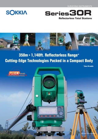
 Series30R Reflectorless Total Stations 350m • 1,140ft. Reflectorless Range* Cutting-Edge Technologies Packed in a Compact Body * Class 3R models Laser beam image is simulated.
  • 2. Series30R Innovative Technology Makes Reflectorless EDM More Powerful Than Ever ■ New advances with RED-tech EDM Sokkia’s revolutionary digital signal processing technology, RED-tech, relies on a unique procedure for measurement beam analysis. Using an A/D converter, it simultaneously samples measuring signals in three different frequencies. Furthermore, RED-tech uses advanced software to calculate distances. As a result, RED-tech ensures that the calculation method most suited to the condition of the measuring beam is selected. It also is able to deliver greater accuracy, speed, and range. And now, RED-tech has been further enhanced through the inclusion of improved optical and electronic components. Its new light emitting and receiving optics provide the ideal light path for capturing light with minimal loss. And its new highly tunable optical filter, which captures multiple samples of beams carrying the correct measurement information, gives you greater precision with difficult-to-measure objects. Thanks to these new components and its advanced technology, RED-tech EDM paves the way to unprecedented distance measurement possibilities. Sampling image ■ Ultra-wide reflectorless measurement range From extra-long distances to remarkably short ones, the Series30R offers accurate reflectorless measurement over a tremendous range of distances. The Series30R total stations feature a Class 3R laser, and cover a range from 0.3m to 350m (1ft. to 1,140ft.). Models equipped with a Class 2 laser are also available. These have a reach of up to 150m (490ft.) or 100m (320ft.). Distances based on use of the white side of a KODAK Gray Card. ■ Reflectorless measurement ■ Sokkia’s traditional optics range and accuracy with a Kodak Gray Card Sokkia’s traditional optics have never been more refined. Light is projected from the middle of an SET230R3 • SET330R3 • SET530R3 objective lens and received along its periphery. Class 3R laser products When combined with a narrow measuring beam, this White side ±(3 + 2ppm x D)mm design enables pinpoint measurement and is highly 90% reflective effective even with narrow objects. Furthermore, the Gray side 200m (650ft.) 350m (1,140ft.) ±(3 + 2ppm x D)mm new telescope provides an extremely bright and 18% reflective ±(5 + 10ppm x D)mm sharp sight. 0.3m (1ft.) 100m (320ft.) 170m (550ft.) ±(5 + 5ppm x D)mm SET230R • SET330R • SET530R Class 2 laser products White side ±(3 + 2ppm x D)mm 90% reflective ±(5 + 10ppm x D)mm 100m (320ft.) 150m (490ft.) Gray side 18% reflective ±(5 + 5ppm x D)mm 0.3m (1ft.) 45m (140ft.) 80m (260ft.) ±(3 + 2ppm x D)mm Receiver SET630R Class 2 laser product White side ±(3 + 2ppm x D)mm 90% reflective Transmitter 100m (320ft.) Optics diagram Gray side 18% reflective ±(5 + 5ppm x D)mm 0.3m (1ft.) 30m (98ft.) 50m (160ft.) ±(3 + 2ppm x D)mm
  • 3. ■ Ultra-narrow visible laser for pinpoint accuracy A A Series30R: The ultra-narrow laser beam enables accurate measurements through obstacles such as chain-link fences, tree branches, etc. Broader beam models: Both the fence and wall get measured, which leads to erroneous measurement. B C Series30R: Measurements at small incident angles, such as with A manholes on the C road surface, are handled with high B B precision by the Series30R: ultra-narrow laser The measuring beam is measuring beam. extremely narrow, so Broader beam models: distances to walls and Wider measuring beams end corners can be measured up covering a larger area with pinpoint accuracy. than expected at small incident angles, resulting in Broader beam models: A wide measurements that are too measuring beam hits points near C long or short. and far at the same time, resulting in inaccurate measurement. The Series30R employs an ultra small-diameter visible laser to obtain measurements with pinpoint accuracy. Fine objects, as well as the corners of walls and other structures, can be measured precisely. You can also make accurate measurements through obstacles such as chain-link fences and tree branches. ■ Laser-pointer function The visible laser beam can be used as a convenient laser pointer for interior leveling work, vertical alignment, setting out, and other tasks. ■ Long-distance measurement with reflectors Measure long distances by directing the laser beam at a reflector. When using a single AP prism, you can measure as far as 5,000m (16,400ft.)* at once, with an accuracy of ±(2 + 2ppm x D)mm. In addition, reflective sheet targets may be used to get measurements of up to 500m (1,640ft.)** with ±(3 + 2ppm x D)mm precision. Choose from Sokkia’s wide selection of sheet targets to suit your needs. Rotating pin-pole targets, two-point target for measuring hidden points, and many other innovative reflective targets are available. * In good weather conditions except SET630R. ** When using RS90N-K. In the reflective sheet or prism modes, maximum laser output is automatically reduced to 0.22mW. This is equivalent to the level of a Class 1 laser. The Series30R also includes a safety filter in the telescope, which protects your eye from the laser beam if you happen to sight a reflective prism or sheet target while in reflectorless mode.
  • 4. Series30R A Durable Partner That Gives Heavy-Duty Support for Daily Surveying Needs ■ Sokkia's original absolute encoder ■ Status check at a glance The built-in control panel has an easy-to-view LCD screen with 192 x 80 pixel resolution. Key information, such as EDM mode (reflectorless, prism, or reflective sheet target) and laser beam status, can be checked at a glance. LED CCD Absolute encoder disk Encoder diagram The Series30R models are equipped with Sokkia-developed absolute encoders. These encoders feature the RAB (RAndom Bi-directional) code technology first used in the SDL30 digital level, which provides high stability and reliability. You do not need to reset for 0 indexing at the start of a job, so surveying can begin from the moment you turn on the power. Work efficiency is also boosted by the immediate Reflectorless mode display of azimuth whenever you restart the total station. ■ Triple-axis compensation for high reliability Vertical and horizontal angles are compensated for by a dual-axis Reflective sheet Prism mode compensator that detects the tilt of the total station in two directions. target mode In addition, a collimation function corrects the deviation of the telescope's mechanical axis. Working together, these features offer maximum reliability with angle measurements. ■ One-touch target selection ■ Password function for security There are no complicated operations when it comes to selecting The Series30R includes a password-protection function for security targets. The Series30R total stations let you switch between purposes. You can assign your own password to the instrument to reflectorless, prism, and reflective sheet target just by pressing the prevent unauthorized use. SFT key in sequence. The selected target is displayed on the operation panel for easy confirmation. ■ Large internal memory ■ User-friendly keyboard and softkeys The Series30R can store approximately 10,000 data points, including The control panel also includes large, ergonomic buttons as well as known points and other information. To facilitate concurrent use at four softkeys (F1-F4). Softkey functions are structured into 3 pages different work sites, data may be sorted into 10 different job files. and 12 modes, and you are free to assign functions to any key you like. Productivity is enhanced through this balance of functionality and ease of use. ■ CompactFlash card unit (Factory option*) ■ Exceptional durability A card unit for commercially available CompactFlash memory cards can be Featuring advanced protection against water and dust, the added as a factory option. 72,000 points Series30R total stations are ideal for use in inclement weather, (eighteen 4,000-point files) can be stored humid environments, or at dusty work sites. (IP66 compliant) with an 8MB memory card, while a 16MB memory card provides 144,000 points of data storage (thirty-six 4,000-point files). * Not available for SET630R
  • 5. ■ SF14 wireless keyboard (Option*) ■ Guide Light Unit GDL1 (Factory option) This wireless keyboard has a total of 37 keys (including alphanumeric keys, softkeys, and measurement controls), to enable quick and easy data entry of point names and coordinate values. Protection against dust and water is another advantage, as you can use the keyboard without worry in the rain or The Guide Light Unit GDL1 boosts efficiency of setting-out at a dusty measurements. Its guide light is composed of two lights of different construction site. colors that are emitted from one aperture. When you are on the left (IP44 compliant) side, the green light is visible, and when you are on the right side, the red light can be seen. When green and red are flashing back and * Not available for SET630R forth, you are on the telescope sighting direction. ■ FOF sensors* Sokkia's original and extremely compact FOF (Fiber made of Optical Filter material) sensors are mounted on two sides of the instrument for communication with The light may be used up to a range of A special flashing pattern is also included the SF14 wireless keyboard. These sensors 150m (490ft.). to assist users with color weakness. are extremely resistant to light interference, and have a wide signal reception range to Guide Light Unit GDL1 Green LED (524nm) and Red LED (630nm) (Class 1 LED) allow comfortable use of the keyboard. Visible range 1.3m to 150m (4.3ft. to 490ft.) Visible width Horizontal & vertical: more than ±4˚; approx. 7m at 100m (23ft. at 320ft.) * Not included on SET630R Center resolution Within 4'; approx. 12cm at 100m (4.7in. at 320ft.) FOF sensor The Guide Light Unit cannot be used simultaneously with the laser pointer function. ■ Compact lithium-ion battery Take 6 hours of continuous angle and distance measurements with the Series30R's rechargeable lithium-ion battery. Unlike Ni-Cd cells, the Series30R's battery can be fully recharged at any time, without diminishing its energy capacity. The BDC46A battery is commonly used for Sokkia's Series10 total stations, digital levels, and other equipment. 3R 2/II * ** *** * Factory option for all models ** Option for all models except SET630R *** Factory option for all models except SET630R
  • 6. Series30R Packed with Versatile Functions for High Work Efficiency at Diverse Sites ■ Missing Line Measurement (MLM) ■ Offset/Distance At the touch of a key, the Series30R measures horizontal The Series30R calculates distance, slope distance, height difference and percentage of the angles and distance, slope between two points. or the coordinates of the Measuring measuring point by Point inputting the distance and direction between the ■ Remote Elevation Measurement (REM) measuring point and the offset point. The Series30R easily determines the height of a point where distance cannot be measured directly. Sight a point either directly above or directly below the target point, and then sight the target point. ■ Offset/Angle The Series30R automatically calculates the position of measuring points. First, ■ 3-D Coordinate Measurement Measuring measure a point on either Point The Series30R calculates side of the measuring 3-D coordinate values of point at the same measuring points and Offset Point distance from the displays them either as N, Series30R instrument. E, Z or E, N, Z. Then sight the measuring Z N point. E ■ Two-Distance Offset With the use of a 2RT500-K two-point target, the Series30R ■ Automatic Azimuth Angle Setting can measure hidden points easily and efficiently. Set the Known Station The Series30R can two-point target on the measuring point (the target does not automatically set the have to be perpendicular), measure targets A and B, and horizontal angle to the input the length between Azimuth Angle azimuth of a back sight by target B and the Z N using the coordinates of measuring point. The the instrument station and Series30R calculates the E A the back sight point. position of the measuring Instrument Station (known) B point in angles and distance, or in coordinate values. ■ Resection ■ Setting Out The Series30R can determine the azimuth and coordinates of The Series30R performs an unknown instrument station with 2 to 10 known points. three-dimensional setting When using two points, measure both angles and distances. out with N, E and Z or E, When using three or more points, the distance is not required. N and Z coordinates. Station elevation from known reference points (up to 10 Directions and distances points) can also be Z N to the setting out position calculated and each Known Station Known Station are indicated on the deviation of multiple E screen. Azimuth Angle reference points is N Z displayed. If a bad point is selected it can be E recalculated, re-observed Instrument Station or replaced with a new (unknown) point.
  • 7. ■ Set-out Line The Set-out line program is used for setting out and checking alignment of curb lines, construction boards and grades of Laser beam image is simulated. pipes. A baseline or an offset from baseline can be defined. When calculating the measuring point, it's possible to calculate and use the scaled down coefficient of the distance and surveyed value that was calculated using the known coordinate values of 2 points. ■ Point Projection This program projects a point onto a line. It calculates the distance and offset of the point relative to the specified baseline, and it computes the coordinates of the intersection point, which can then be directly set out. Elevations are interpolated where possible. When calculating the measuring point, it's possible to calculate and use the scaled down coefficient of the distance Standard accessories and surveyed value that was calculated using the known coordinate values of 2 points. BDC46A rechargeable battery: 2 pcs. (SET630R: 1 pc.) ● CDC61/62/64 quick charger ● CP7 tubular FROM POINT TO POINT MEASURED POINT compass ● Lens hood ● Lens cap ● Plumb bob ● Tool OFFSET kit ● Wiping cloth ● Operator's manual ● Carrying case and shoulder strap FROM POINT TO POINT Optional accessories SF14 wireless keyboard* ● GDL1 guide light unit (factory Set-out Line and Point Projection option) ● CF card unit* (factory option) ● BDC12 Ni-Cd large external battery*, EDC3 power cable for BDC12 (2m)*, EDC7 power cable for BDC12 (0.5m)*, CDC14 battery charger for BDC12* ● EDC2A AC power adapter (100 to 240V)* ● EDC14 external battery adapter*, EDC5 ■ Area Calculation car battery cable for EDC14*, EDC4 car cigarette lighter The Series30R can use cable for EDC14* ● OF3A solar filter ● DE25 diagonal measured points or eyepiece ● EL6 eyepiece for SET630R (30x) ● DOC46 stored data to calculate printer cable ● DOC25 (25 pins, male), DOC26 (25 pins, an area. female), DOC 27 (9 pins, female), DOC1 (w/o connector) interface cables ● SC189 back pack * Except SET630R For more information, please consult your local dealer.
  • 8. Series30R REFLECTORLESS TOTAL STATIONS SPECIFICATIONS SET230R3 ·SET330R3 ·SET530R3 ·SET230R ·SET330R ·SET530R ·SET630R Model SET230R3 SET330R3 SET530R3 SET230R SET330R SET530R SET630R Laser class*1 Class 3R Laser Product Class 2 Laser Product Telescope Fully transiting, coaxial sighting and distance measuring optics Magnification 30x 26x Resolving power 2.5" 3.5" Others Length: 171mm (6.7in.), Objective aperture: 45mm (1.8in.) (EDM 48mm (1.9in.)), Image: Erect, Field of view: 1˚30' (26m/1,000m), Minimum focus: 1.3m (4.3ft.), Reticle illumination: 5 brightness levels. Angle measurement Photoelectrical absolute encoder scanning. Both circles adopt diametrical detection. Unit Degree / Gon / Mil, selectable Display resolutions 1" / 5", 0.2 / 1mgon, 0.005 / 0.02mil, selectable Accuracy (ISO12857-2:1997) 2" / 0.6mg / 0.01mil 3" / 1mg / 0.015mil 5" / 1.5mg / 0.025mil 2" / 0.6mg / 0.01mil 3" / 1mg / 0.015mil 5" / 1.5mg / 0.025mil 6" / 1.9mg / 0.03mil Measuring time 0.5s or less, continuous Measurement mode H: Clockwise / Counterclockwise, selectable. 0 set, Hold, Angle input, Repetition, available. V: Zenith 0 / Horizontal 0 / Horizontal 0± / Slope in %, selectable Automatic dual-axis compensator Dual-axis liquid tilt sensor, Working range: ±3' (±55mg) Collimation compensation On / Off, selectable Fine motion screws 2-speed motion 1-speed motion 2-speed motion 1-speed motion Distance measurement Modulated laser, phase comparison method with red laser diode, coaxial optics Laser output Reflectorless mode: Class 3R equivalent (max. 5mW) Reflectorless mode: Class 2 equivalent (max. 0.99mW) Prism/Sheet mode: Class 1 equivalent (max. 0.22mW) Prism/Sheet mode: Class 1 equivalent (max. 0.22mW) Unit meters / feet / feet-inches, selectable Measuring range Reflectorless* 2 0.3 to 350m (1 to 1,140ft.) (White side, 90% reflective) 0.3 to 150m (1 to 490ft.) (White side, 90% reflective) 0.3 to 100m (320ft.) (slope distance) (with Kodak Gray Card) 0.3 to 170m (1 to 550ft.) (Gray side, 18% reflective) 0.3 to 80m (1 to 260ft.) (Gray side, 18% reflective) (white side, 90% reflective) With reflective sheet target RS90N-K: 1.3 to 500m (1,640ft.), RS50N-K: 1.3 to 300m (980ft.), RS10N-K: 1.3 to 100m (320ft.) With mini prisms CP01: 1.3 to 800m (2,620ft.), OR1PA: 1.3 to 500m (1,640ft.) With 1 AP prism A* 4 1.3 to 4,000m (13,120ft.), 1.3 to 3,000m (9,840ft.) G* 5 1.3 to 5,000m (16,400ft.) 1.3 to 4,000m (13,120ft.) With 3 AP prisms A* 4 to 5,000m (16,400ft.) to 4,000m (13,120ft.) G* 5 to 6,000m (19,680ft.) to 5,000m (16,400ft.) Display resolutions Fine, Rapid single: 0.001m / 0.01ft. / 1/8in. Tracking: 0.01m / 0.1ft. / 1/2in. Accuracy Reflectorless* 2/*3 0.3 to 200m (1 to 650ft.): ±(3 + 2ppm x D)mm 0.3 to 100m (1 to 320ft.): ±(3 + 2ppm x D)mm ±(3 + 2ppm x D)mm (D=measuring (Fine mode) Over 200 to 350m (over 650 to 1,140ft.): ±(5 + 10ppm x D)mm Over 100 to 150m (over 320 to 490ft.): ±(5 + 10ppm x D)mm distance, unit: mm) Reflectorless*2/*3 0.3 to 200m (1 to 650ft.): ±(6 + 2ppm x D)mm 0.3 to 100m (1 to 320ft.): ±(6 + 2ppm x D)mm ±(6 + 2ppm x D)mm (Rapid single mode) Over 200 to 350m (over 650 to 1,140ft.): ±(8 + 10ppm x D)mm Over 100 to 150m (over 320 to 490ft.): ±(8 + 10ppm x D)mm With reflective sheet target Fine: ±(3 + 2ppm x D)mm, Rapid single: ±(6 + 2ppm x D)mm With AP prism Fine: ±(2 + 2ppm x D)mm, Rapid single: ±(5 + 2ppm x D)mm Measuring time Fine mode Repeat: Every 1.3s (initial 2.6s) Rapid single / Tracking Rapid single: 1.8s / Tracking: Every 0.3s (initial1.6s) Measuring mode Fine (single / repeat / average), Rapid (single), Tracking Atmospheric correction / Prism constant correction Temperature / Pressure / ppm input, available. / -99 to +99mm (1mm steps). 0 fixed in reflectorless mode. Refraction & earth-curvature correction ON (K=0.142 / 0.20) / OFF, selectable Data storage and transfer Data storage Internal memory Approx. 10,000 points CF memory card unit Factory option. The 8MB CF card stores approx. 72,000-point data. — Scale factor setting 0.5 to 2.0 Interface Asynchronous serial RS-232C compatible, Baud rate 1,200 to 38,400bps Printer output Centronics compatible (with optional DOC46 printer cable) General Display / Keyboard Alphanumeric/graphic dot matrix LCD, 192 x 80 dots, with backlight, with contrast adjustment / 4 soft keys and 11 keys Control panel location On both faces On one face Wireless keyboard SF14 Optional — Laser-pointer function ON (auto off in 5 minutes) / OFF, selectable. (Does not work simultaneously with the Guide Light.) Guide light GDL1 Factory option Sensitivity of levels Plate level 20" / 2mm 30" / 2mm 20" / 2mm 30" / 2mm 40" / 2mm Circular / Graphic Circular level: 10' / 2mm / Graphic LCD level: 3' / outer circle Optical plummet / Tribrach Image: Erect, Magnification: 3x, Minimum focus: 0.3m (0.98ft.) / Detachable Dust and water protection / Operating temperature Conforms to IP66 (IEC 60529:1989) / -20 to +50˚C (-4 to +122˚F) Instrument height / Size with handle and battery 236mm (9.3in.) from tribrach bottom / W 165 x D 171 x H 341 mm (W 6.5 x D 6.7 x H 13.5 in.) Weight with handle and battery Approx. 5.4kg (12 lb.) Approx. 5.3kg (11.6 lb.) Power supply 7.2V DC BDC46A detachable Li-Ion rechargeable battery 2 BDC46A are included. 1 BDC46A is included. Continuous use (at 25˚C (77˚F)) Approx. 5.5 hours (650 points) for single measurement every 30s Approx. 6 hours (700 points) for single measurement every 30s Approx. 8.5 hours for angle measurement only Recharging time (at 25˚C (77˚F)) Within 2 hours with CDC61/62/64 standard quick chargers. BDC12 external Ni-Cd battery (optional) Approx. 22 hours for single measurement every 30s Approx. 22.5 hours for single measurement every 30s — continuous use (at 25˚C (77˚F)) Approx. 29 hours for angle measurement only Approx. 30 hours for angle measurement only Automatic power cut-off Auto-off time is selectable from 30, 15, 10, 5 minutes or none. Resume function On / Off selectable (backed up for approx. 1 week). *1 IEC 60825-1Amd.2: 2001 / FDA CDRH 21 CFR Part1040.10 and 1040.11 (Complies with FDA performance standards for laser products except for deviations pursuant to Laser Notice No.50, dated July 26,2001.) *2 Reflectorless range/accuracy may be varied according to measuring objects, observation situations and environmental conditions. *3 With Kodak Gray Card White Side (90% reflective) *4 Average conditions: Slight haze, visibility about 20km (12 miles), sunny periods, weak scintillation. *5 Good conditions: No haze, visibility about 40km (25 miles), overcast, no scintillation. 5 3R Sokkia is a sponsor of the KODAK is a registered trademark of the Eastman KODAK Company. Sokkia is a trademark of Sokkia Co., Ltd. Product names mentioned in this brochure are trademarks of their respective owners. International Federation Designs and specifications are subject to change without notice. Product colors in this brochure may vary slightly from those of the actual products owing to limitations of the printing process. of Surveyors ISO9001 Certified (JQA-0557) http://www.sokkia.co.jp/english/ INTERNATIONAL SALES DEPARTMENT 260-63 HASE, ATSUGI, KANAGAWA, 243-0036 JAPAN PHONE +81-46-248-7984 FAX +81-46-247-1731 A-182-E-6-0406-CH-AB Printed in Japan on 100% recycled paper with ecologically safe soy ink. © 2004 SOKKIA CO., LTD.