SlideShare ist ein Scribd-Unternehmen logo
1 von 10
Downloaden Sie, um offline zu lesen
Mealy state machine
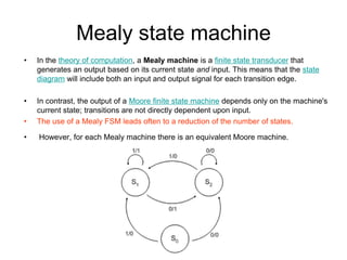
•   In the theory of computation, a Mealy machine is a finite state transducer that
    generates an output based on its current state and input. This means that the state
    diagram will include both an input and output signal for each transition edge.

•   In contrast, the output of a Moore finite state machine depends only on the machine's
    current state; transitions are not directly dependent upon input.
•   The use of a Mealy FSM leads often to a reduction of the number of states.

•   However, for each Mealy machine there is an equivalent Moore machine.
Mealy state machine
Moore state machine
•   In the theory of computation, a Moore machine is a finite state transducer
    where the outputs are determined by the current state alone (and do not
    depend directly on the input). The state diagram for a Moore machine will
    include an output signal for each state. Compare with a Mealy machine,
    which maps transitions in the machine to outputs.
•   The advantage of the Moore model is a simplification of the behavior.
Moore state machine
Example
• Q3.Derive a minimal state table for a single-input and
  single-output Moore-type FSM that produces an output
  of 1 if in the input sequence it detects either 110 or 101
  patterns. Overlapping sequences should be detected.
  (Show the detailed steps of your solution.)
State Diagram
                Reset

                                      w=0
                                                                            w=0


                                w=1               w=0                       w=1

                  A/z=0                B/z=0                  E/z=0               F/z=1


                                         w=1
                                                                 w=1


                                                        w=1
                          w=0          C/z=0


                                                                      w=1
                                            w=0


State Diagram

                                       D/z=1
Sate Table (Moore FSM)

  Present        Next State              Output
   state                                    Z
                  w=0   w=1

     A            A      B                 0


     B            E      C                 0


     C            D      C                 0


     D            A      F                 1


     E            A      F                 0


     F            E      C                 1


            6 states need 3 flip-flops
State   Assignment (Mealy FSM):
state   A: Got no 1
state   B: Got”1”
state   C: Got”11”
state   D: Got”10”


                                  Reset

                                                                        1/0


                                          1/0               1/0
                  0/0               A             B                 C

                                            1/1       0/0

                                   0/0
                                                                  0/1
                                                  D
                  State Diagram
Sate Table (Mealy FSM)

  Present         Next State             Output Z
   state
                  w=0   w=1          w=0      w=1

     A             A      B              0     0


     B             D      C              0     0


     C             D      C              1     0


     D             A      B              0     1


            4 states need 2 flip-flops

Weitere ähnliche Inhalte

Was ist angesagt?

Mealy and moore machine
Mealy and moore machineMealy and moore machine
Mealy and moore machineEhatsham Riaz
 
UNIT-V-FPGA &CPLD ARCHITECTURES AND APPLICATIONS
UNIT-V-FPGA &CPLD ARCHITECTURES AND APPLICATIONSUNIT-V-FPGA &CPLD ARCHITECTURES AND APPLICATIONS
UNIT-V-FPGA &CPLD ARCHITECTURES AND APPLICATIONSDr.YNM
 
Asynchronous Sequential Circuit-Unit 4 ppt
Asynchronous Sequential Circuit-Unit 4 pptAsynchronous Sequential Circuit-Unit 4 ppt
Asynchronous Sequential Circuit-Unit 4 pptSIVALAKSHMIPANNEERSE
 
Introduction to Counters
Introduction to CountersIntroduction to Counters
Introduction to CountersISMT College
 
synchronous state machine design
synchronous state machine designsynchronous state machine design
synchronous state machine designAdarsh Patel
 
Finite state automaton
Finite state automatonFinite state automaton
Finite state automatonAmmAr mobark
 
Introduction state machine
Introduction state machineIntroduction state machine
Introduction state machineShreyans Pathak
 
Sequential circuits in Digital Electronics
Sequential circuits in Digital ElectronicsSequential circuits in Digital Electronics
Sequential circuits in Digital ElectronicsVinoth Loganathan
 
Lec 07 - ANALYSIS OF CLOCKED SEQUENTIAL CIRCUITS
Lec 07 - ANALYSIS OF CLOCKED SEQUENTIAL CIRCUITSLec 07 - ANALYSIS OF CLOCKED SEQUENTIAL CIRCUITS
Lec 07 - ANALYSIS OF CLOCKED SEQUENTIAL CIRCUITSVajira Thambawita
 
Spi master core verification
Spi master core verificationSpi master core verification
Spi master core verificationMaulik Suthar
 
Synchronous state machines. Moore and Mealy state machines (FSM)
Synchronous state machines.  Moore and Mealy state machines (FSM)Synchronous state machines.  Moore and Mealy state machines (FSM)
Synchronous state machines. Moore and Mealy state machines (FSM)Mumbi Chishimba
 
melay and moore machine.pptx
melay and moore machine.pptxmelay and moore machine.pptx
melay and moore machine.pptxssuser1b2fab
 
state diagrams of flip flops
 state diagrams of flip flops state diagrams of flip flops
state diagrams of flip flopsUnsa Shakir
 

Was ist angesagt? (20)

Mealy and moore machine
Mealy and moore machineMealy and moore machine
Mealy and moore machine
 
UNIT-V-FPGA &CPLD ARCHITECTURES AND APPLICATIONS
UNIT-V-FPGA &CPLD ARCHITECTURES AND APPLICATIONSUNIT-V-FPGA &CPLD ARCHITECTURES AND APPLICATIONS
UNIT-V-FPGA &CPLD ARCHITECTURES AND APPLICATIONS
 
Asynchronous Sequential Circuit-Unit 4 ppt
Asynchronous Sequential Circuit-Unit 4 pptAsynchronous Sequential Circuit-Unit 4 ppt
Asynchronous Sequential Circuit-Unit 4 ppt
 
Introduction to Counters
Introduction to CountersIntroduction to Counters
Introduction to Counters
 
Verilog
VerilogVerilog
Verilog
 
synchronous state machine design
synchronous state machine designsynchronous state machine design
synchronous state machine design
 
Finite state automaton
Finite state automatonFinite state automaton
Finite state automaton
 
Introduction state machine
Introduction state machineIntroduction state machine
Introduction state machine
 
Sequential circuits in Digital Electronics
Sequential circuits in Digital ElectronicsSequential circuits in Digital Electronics
Sequential circuits in Digital Electronics
 
Counters
CountersCounters
Counters
 
Lec 07 - ANALYSIS OF CLOCKED SEQUENTIAL CIRCUITS
Lec 07 - ANALYSIS OF CLOCKED SEQUENTIAL CIRCUITSLec 07 - ANALYSIS OF CLOCKED SEQUENTIAL CIRCUITS
Lec 07 - ANALYSIS OF CLOCKED SEQUENTIAL CIRCUITS
 
Spi master core verification
Spi master core verificationSpi master core verification
Spi master core verification
 
Jk flip flop
Jk flip flopJk flip flop
Jk flip flop
 
Synchronous state machines. Moore and Mealy state machines (FSM)
Synchronous state machines.  Moore and Mealy state machines (FSM)Synchronous state machines.  Moore and Mealy state machines (FSM)
Synchronous state machines. Moore and Mealy state machines (FSM)
 
melay and moore machine.pptx
melay and moore machine.pptxmelay and moore machine.pptx
melay and moore machine.pptx
 
Verilog lab manual (ECAD and VLSI Lab)
Verilog lab manual (ECAD and VLSI Lab)Verilog lab manual (ECAD and VLSI Lab)
Verilog lab manual (ECAD and VLSI Lab)
 
D Flip Flop
D Flip Flop D Flip Flop
D Flip Flop
 
FSM and ASM
FSM and ASMFSM and ASM
FSM and ASM
 
Actel fpga
Actel fpgaActel fpga
Actel fpga
 
state diagrams of flip flops
 state diagrams of flip flops state diagrams of flip flops
state diagrams of flip flops
 

Mealy state machine

  • 1. Mealy state machine • In the theory of computation, a Mealy machine is a finite state transducer that generates an output based on its current state and input. This means that the state diagram will include both an input and output signal for each transition edge. • In contrast, the output of a Moore finite state machine depends only on the machine's current state; transitions are not directly dependent upon input. • The use of a Mealy FSM leads often to a reduction of the number of states. • However, for each Mealy machine there is an equivalent Moore machine.
  • 3. Moore state machine • In the theory of computation, a Moore machine is a finite state transducer where the outputs are determined by the current state alone (and do not depend directly on the input). The state diagram for a Moore machine will include an output signal for each state. Compare with a Mealy machine, which maps transitions in the machine to outputs. • The advantage of the Moore model is a simplification of the behavior.
  • 5. Example • Q3.Derive a minimal state table for a single-input and single-output Moore-type FSM that produces an output of 1 if in the input sequence it detects either 110 or 101 patterns. Overlapping sequences should be detected. (Show the detailed steps of your solution.)
  • 6.
  • 7. State Diagram Reset w=0 w=0 w=1 w=0 w=1 A/z=0 B/z=0 E/z=0 F/z=1 w=1 w=1 w=1 w=0 C/z=0 w=1 w=0 State Diagram D/z=1
  • 8. Sate Table (Moore FSM) Present Next State Output state Z w=0 w=1 A A B 0 B E C 0 C D C 0 D A F 1 E A F 0 F E C 1 6 states need 3 flip-flops
  • 9. State Assignment (Mealy FSM): state A: Got no 1 state B: Got”1” state C: Got”11” state D: Got”10” Reset 1/0 1/0 1/0 0/0 A B C 1/1 0/0 0/0 0/1 D State Diagram
  • 10. Sate Table (Mealy FSM) Present Next State Output Z state w=0 w=1 w=0 w=1 A A B 0 0 B D C 0 0 C D C 1 0 D A B 0 1 4 states need 2 flip-flops